Silicon Carbide Oven Igniters
Flat and spiral elements.Mounting and connection options for your oven assembly.
Explore SiC igniter configurations with metal brackets, ceramic holders, insulated leads and plug or terminal connections. Find a starting point for your replacement part or OEM design.
- Gas oven bake and broil applications using SiC hot surface ignition
- Mounting: channel brackets, side flanges, mounting plates and lugs
- Connection options: keyed plugs, insulated terminals and exposed lead ends
- Assembly review based on your original part, appliance model or drawing
Oven and range focus
Replacement sourcing and new appliance projects
Element diversity
Flat dual-prong and cylindrical or spiral forms
Mounting diversity
Channels, plates, side flanges and side lugs
Connection diversity
Individual insulated terminals, exposed lead ends and plugs
What Are Silicon Carbide Oven Igniters?
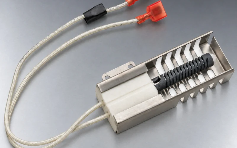
Silicon carbide oven igniters are hot surface ignition components that use an electrically heated silicon carbide (SiC) element to ignite gas burners in compatible ovens and ranges. Assemblies may include a ceramic holder, metal mounting bracket, insulated leads, and a plug or terminal connection. Selecting the right assembly requires matching the appliance’s electrical requirements, burner position, mounting dimensions, and wiring interface.
Product configurations
Oven igniter assemblies for different installation layouts.
Compare the element, mounting hardware and connection in each configuration. Select a reference to use in the part check below.
Oven and range
Vented channel-bracket assembly
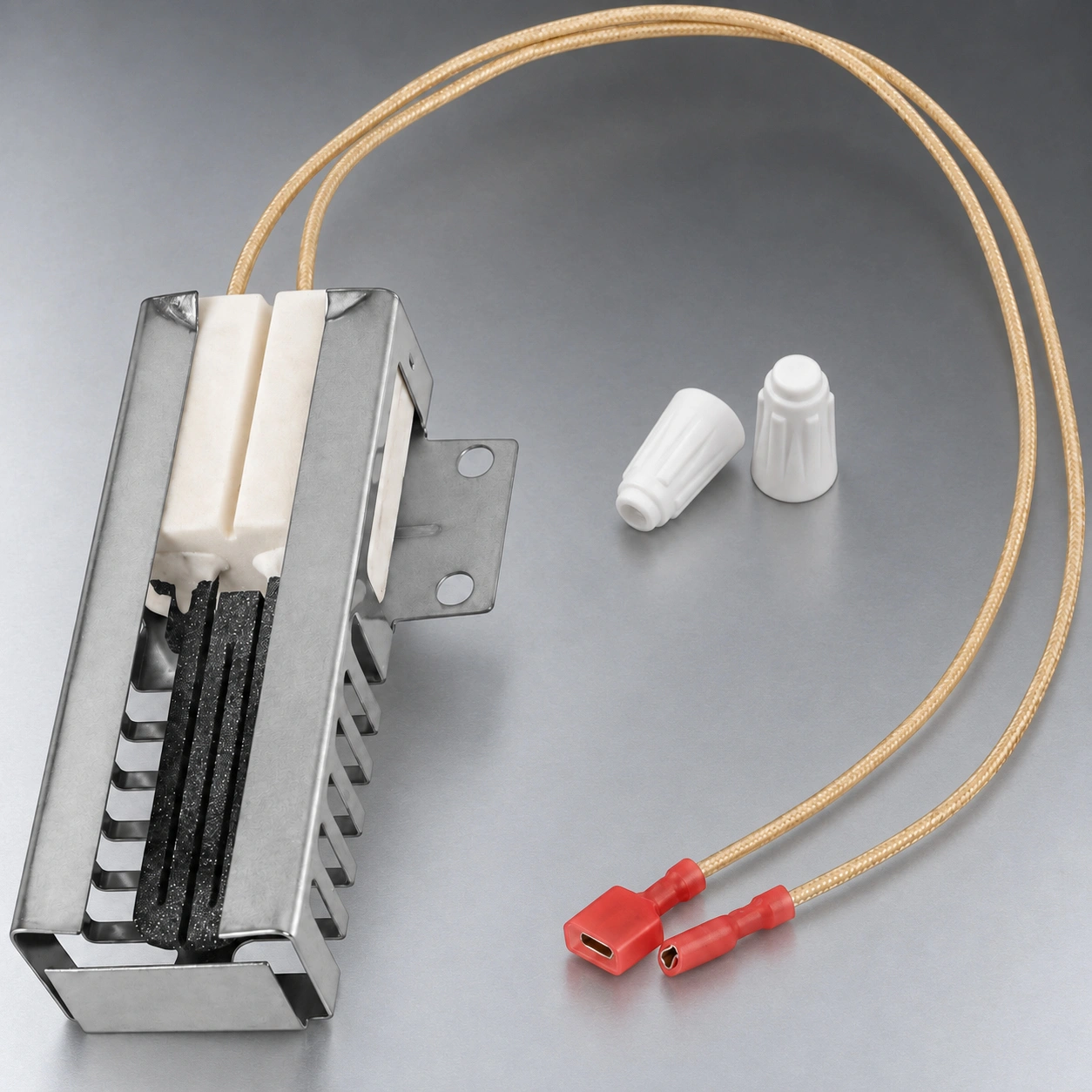
A vented metal channel, side mounting flange and individually terminated insulated leads define this arrangement.
Original equipment references
- Bosch original parts 00487383 and 00492431
Before selection: bracket envelope, hole positions, lead length, terminals, bake or broil position and controls.
Oven and range
Side-flange plug assembly
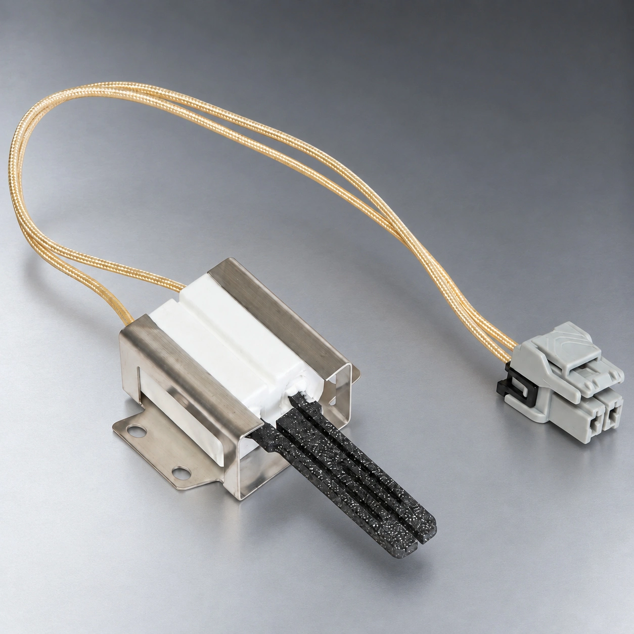
A metal holder with a two-hole side flange surrounds the ceramic body, with insulated leads ending in a plug.
Original equipment references
- GE original part WB13X25500
Before selection: flange orientation, hole spacing, plug interface, lead route, element position and voltage.
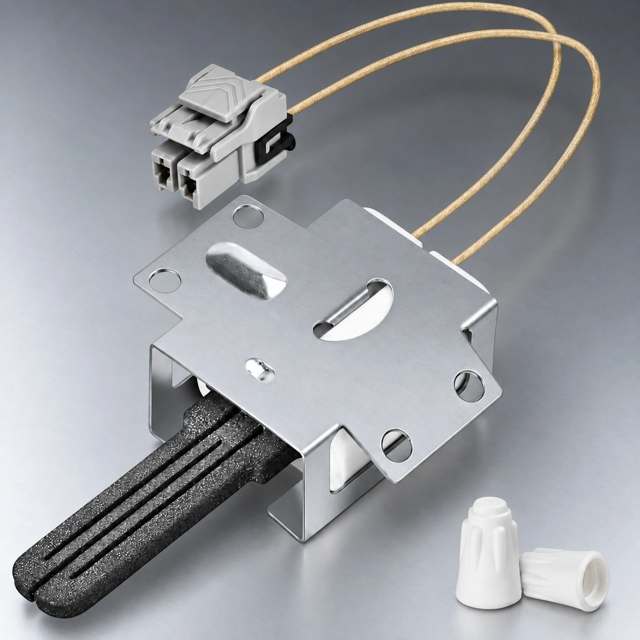
Oven and range
Broad mounting-plate assembly
A broad formed metal plate surrounds the ceramic body, while the flat element projects beyond the plate.
Original equipment references
- GE original part WB13X25500
Before selection: plate outline, hole pattern, connector, lead length, insertion depth and supplied parts.
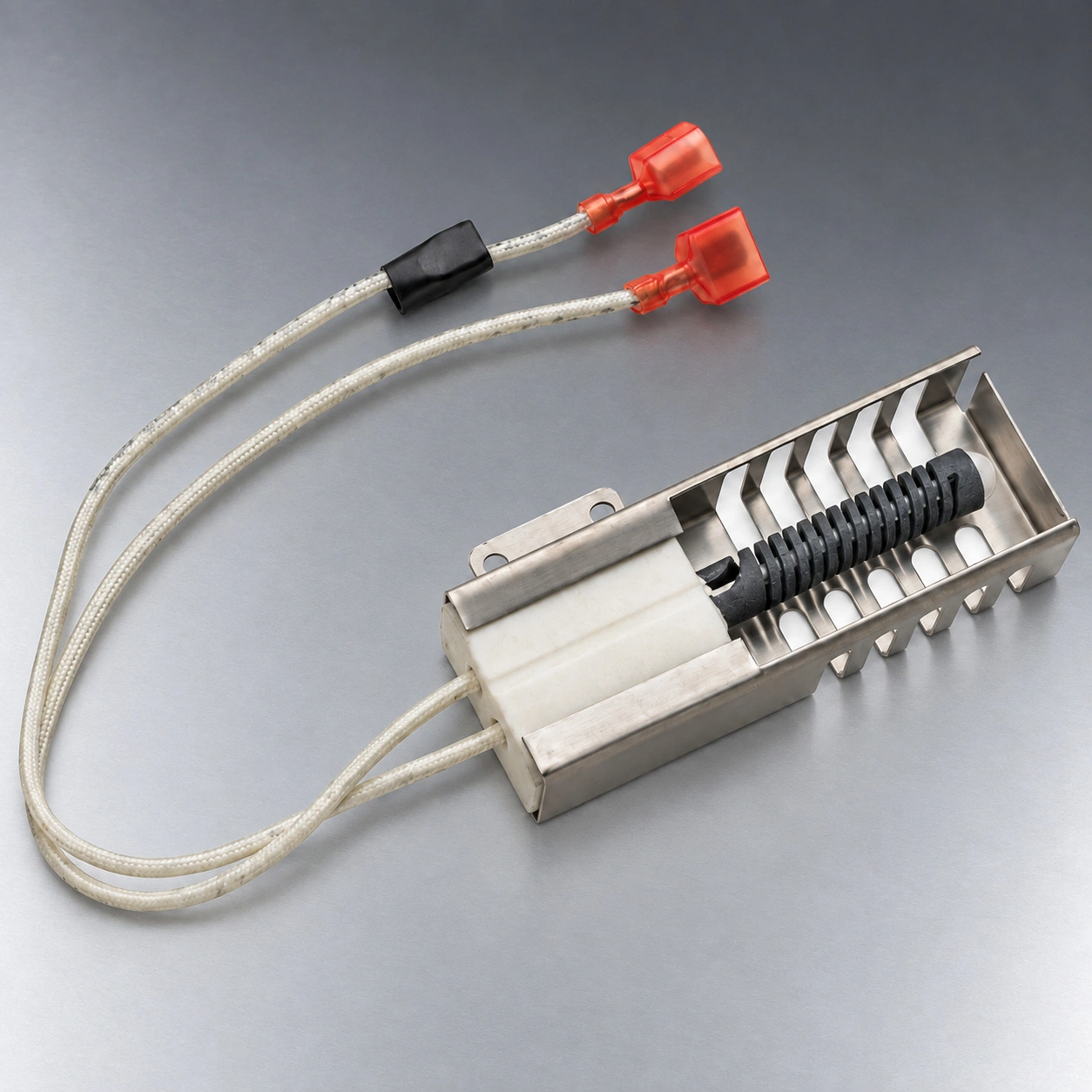
Oven
Cylindrical spiral-element assembly
A spiral-cut cylindrical element sits in a metal channel, with insulated leads ending in individual terminals.
Before selection: element diameter and length, channel orientation, terminals, lead route and control conditions.
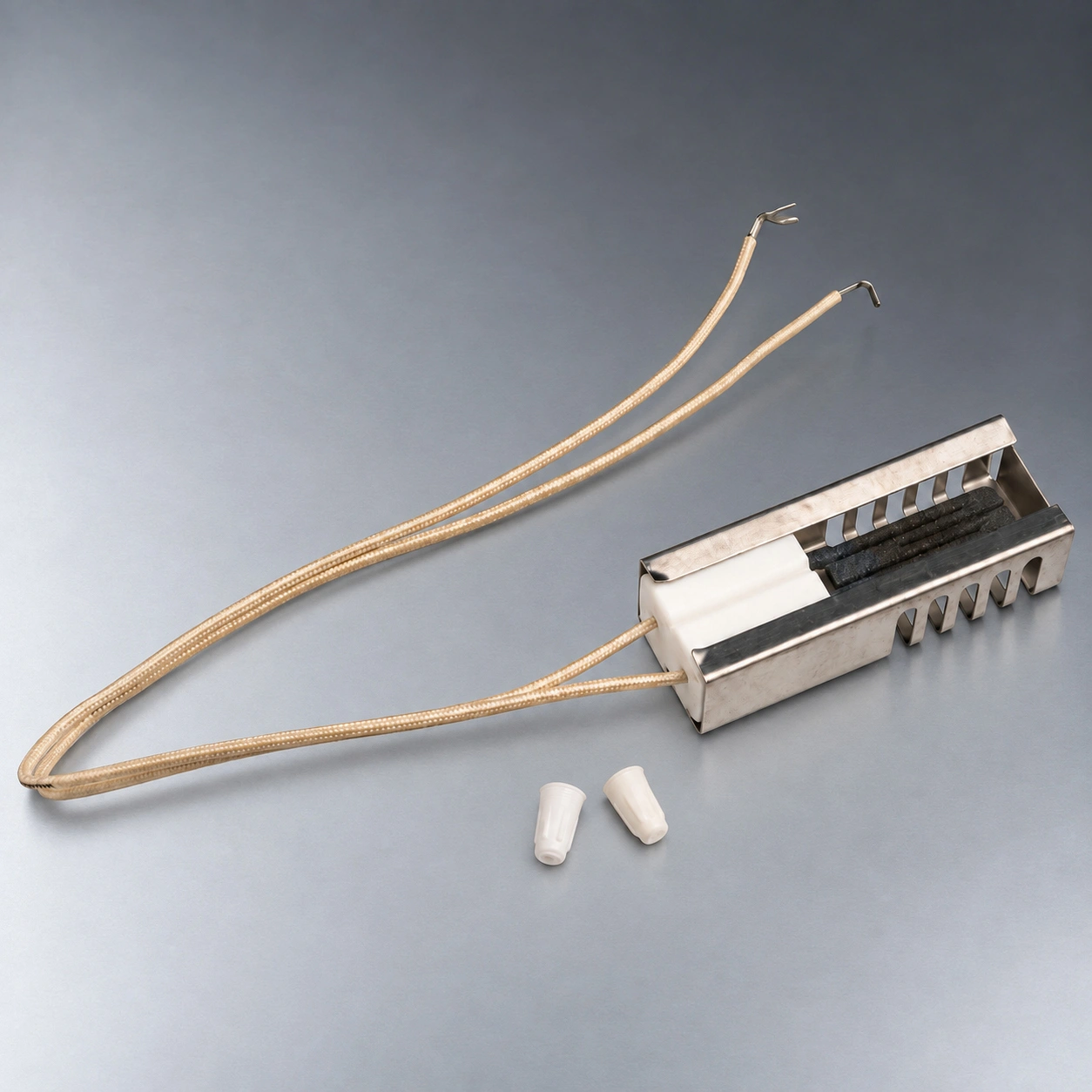
Oven
Flat-element assembly with exposed lead ends
A flat element sits within a vented metal channel, with insulated leads terminating in exposed ends.
Before selection: channel dimensions, hot-zone position, lead length, termination details and installation position.
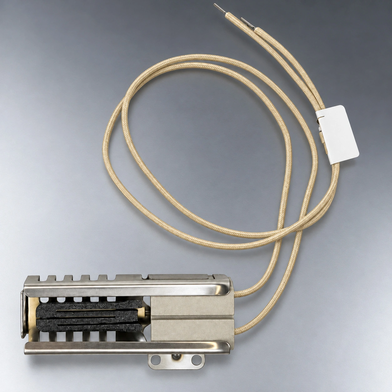
Oven and range
Side-lug channel assembly
A vented metal channel carries a side mounting lug, with insulated leads ending in exposed tips.
Before selection: lug position, mounting holes, lead route, terminations, element position and controls.
Oven and range
Connector-and-bracket assembly
A dedicated bracket, insulated leads and keyed connector provide a distinct appliance interface.
Original equipment references
- Samsung original part DG94-00520A
Before selection: complete appliance model, bracket orientation, connector keying, lead route and electrical conditions.
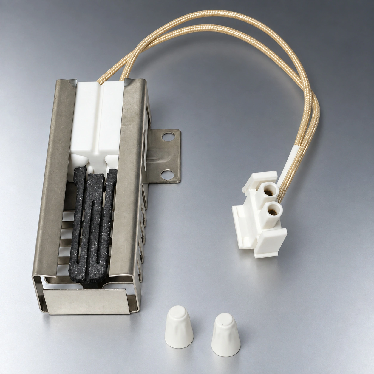
What the configuration gives you
Mounting, wiring and the heating element considered as one assembly.
Overall part length cannot tell you where the active element will sit. The base, bracket and mounting face establish its reach and orientation beside the burner.
01
Mounting options for different oven layouts
Channel, side-flange, plate and lug arrangements give you different mounting references to compare with the space and attachment points in your oven.
For your project
Discuss the installed position and the element together, using the assembly drawing or original part.
02
Connection choices for your existing harness
Plug-connected, terminal-lead and exposed-lead assemblies make the wiring interface visible alongside the igniter itself.
For your project
Identify the connector or termination your harness needs before reviewing a replacement configuration.
03
The element and hardware defined together
Review the SiC element, ceramic holder, metal support and leads as a defined assembly, with any required accessories identified separately.
For your project
Carry one agreed assembly scope into evaluation, purchasing and repeat orders.
Oven & range applications
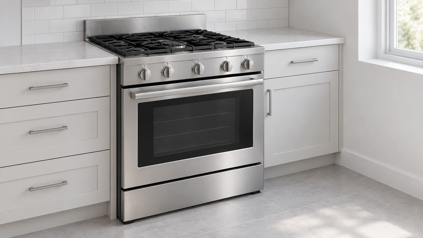
For the gas burner inside your oven.
These assembly configurations are relevant to gas oven and range projects that specify SiC hot surface ignition. Identify the burner position before comparing the part.
Bake burner
Oven baking applications
For the gas bake-burner ignition assembly specified by the appliance. Compare the original igniter, burner mounting and lead route with your required part.
Broil burner, where fitted
Separate gas broiling applications
For appliances with a gas broil burner using the specified SiC ignition system. Treat the broil location as its own part reference when reviewing the assembly.
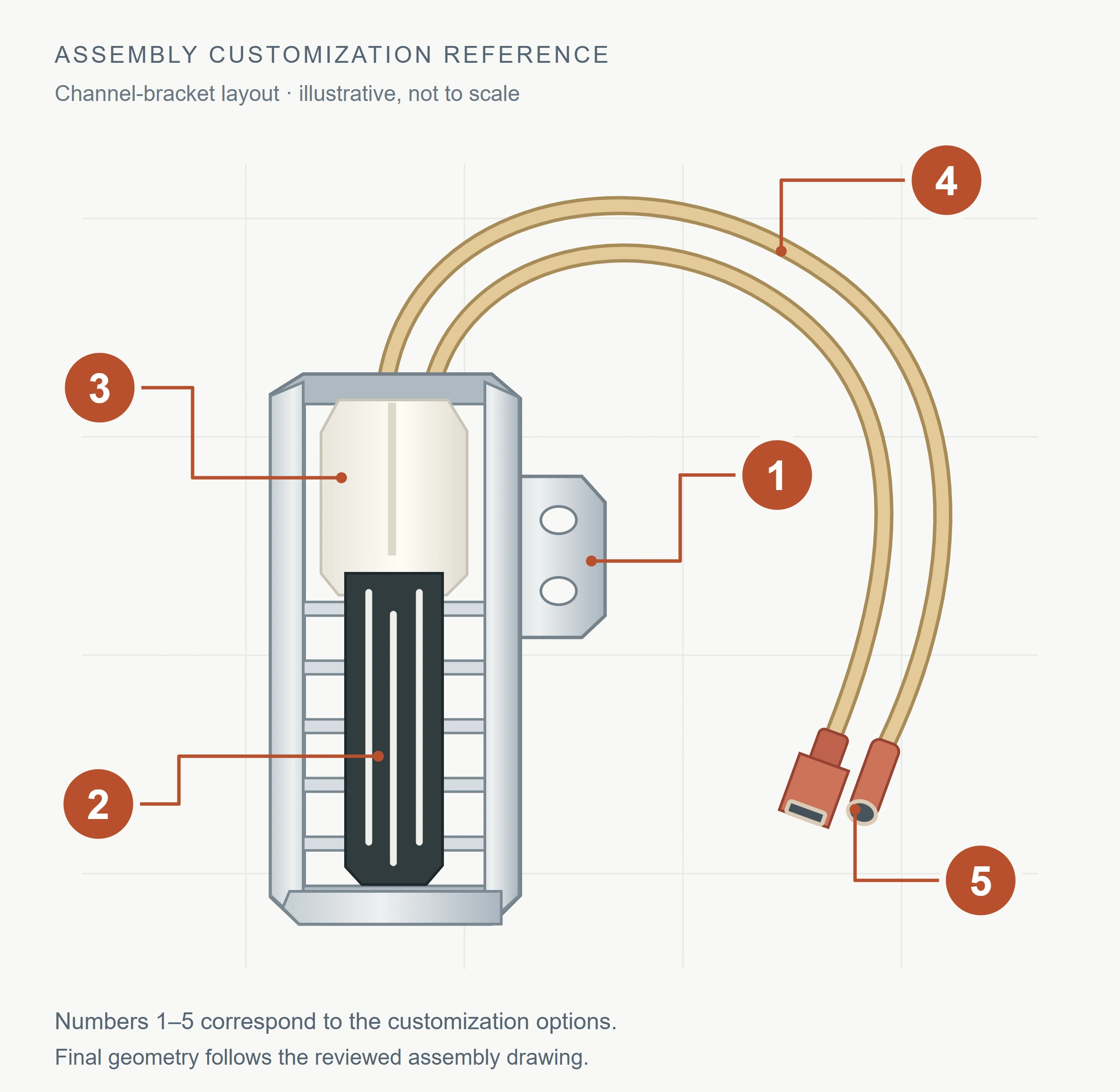
Custom assembly options
Custom Silicon Carbide Oven Igniter Assemblies
Specify the mounting bracket, element position, ceramic holder, lead length and connection for your oven design. Start with a drawing, sample reference or marked photo, and identify the dimensions and interfaces your custom assembly needs to match.
Select the areas to discuss
Your selections will be included in the inquiry below.
Mounting bracket & attachment
Match the fixing points and available installation space.
Share: Hole positions, mounting face and bracket outline.
Element position & geometry
Define where the heating element sits relative to the burner.
Share:Flat / spiral requirement, envelope and projection.
Ceramic holder & support
Review the holder with the bracket and element as one assembly.
Share: Holder envelope, support position and clearances.
Lead length & insulation
Describe the wire route from the igniter to the appliance harness.
Share: Required length, routing and temperature conditions.
Connector or terminal ends
Specify the interface that connects to your existing harness.
Share: Connector face / reference, terminals or exposed ends.
A marked photo is enough to start.
Show what must stay the same and what needs to change. Add a drawing or sample reference, critical dimensions and the appliance’s electrical requirements when available.
Silicon Carbide Oven Igniter Specifications
Select silicon carbide oven igniters by electrical requirements, heat-up response and installed fit. Match the assembly to your oven model and bake or broil burner position, using the original part reference or drawing.
💡 Quick Selection Guide:
Electrical match: Confirm voltage, operating current and ignition-system requirements.
Installation fit: Check bake or broil position, mounting bracket, element reach and burner clearance.
Part identification: Provide the complete oven model, original part number and connector details.
| Property | AD-SIC-RB (RBSC / SiSiC) | AD-SIC-SS (SSiC) |
|---|---|---|
| SiC (wt%) | 85 nominal | ≥99 |
| Free Si | ~15% | None |
| Density (g/cm³) | ≥3.02 | 3.10 typical |
| Open porosity | ≤0.1% | <0.1% |
| Flexural strength (MPa) | 250 @20°C; 280 @1200°C | 380 |
| Compressive strength (MPa) | — (not listed in TDS) | ≥2600 |
| Young’s modulus E (GPa) | 330 @20°C; 300 @1200°C | 420 |
| Thermal conductivity (W/(m·K)) | 45 @1200°C (RT not listed) | 100–120 |
| Application-temperature ceiling (°C) | 1380 | 1600 |
FAQ
Common sourcing questions
No. Keep the complete appliance model and suffix, then verify the bracket, element position, leads, connector and electrical conditions.
Not from shape or voltage alone. The element form, mounting, installed position, electrical conditions and control requirements must be matched to the appliance.
Yes when the quoted bill of materials names those parts. The image does not define package contents by itself.
Provide the drawing revision, mounting envelope, bake or broil position, electrical/control conditions, quantity and acceptance criteria.
No. Mechanical interfaces and electrical requirements both need to match the appliance specification. Use the reference images to describe your part, then confirm the exact configuration.
Ready to discuss your oven igniter?
Share the part reference, quantity and destination. Add the assembly details you have identified above; then discuss sample availability, pricing, minimum quantity and delivery.
- Original part number, oven / range model, or a clear part photo
- For custom assemblies: a drawing or marked photo showing the changes
- Sample or order quantity and delivery country
- Target delivery date, if you have one
No drawing? Start with a photo.
Upload a clear photo of the complete igniter and its connection end. Add the oven model or part number if available.
*Our team will answer your inquiries within 24 hours.
*Your information will be kept strictly confidential.
E-mail
info@adcerax.com
Contact us
Tel:+86-0731-84428843
WhatsApp:+86 19311583352
Response Time
Within 24 hours