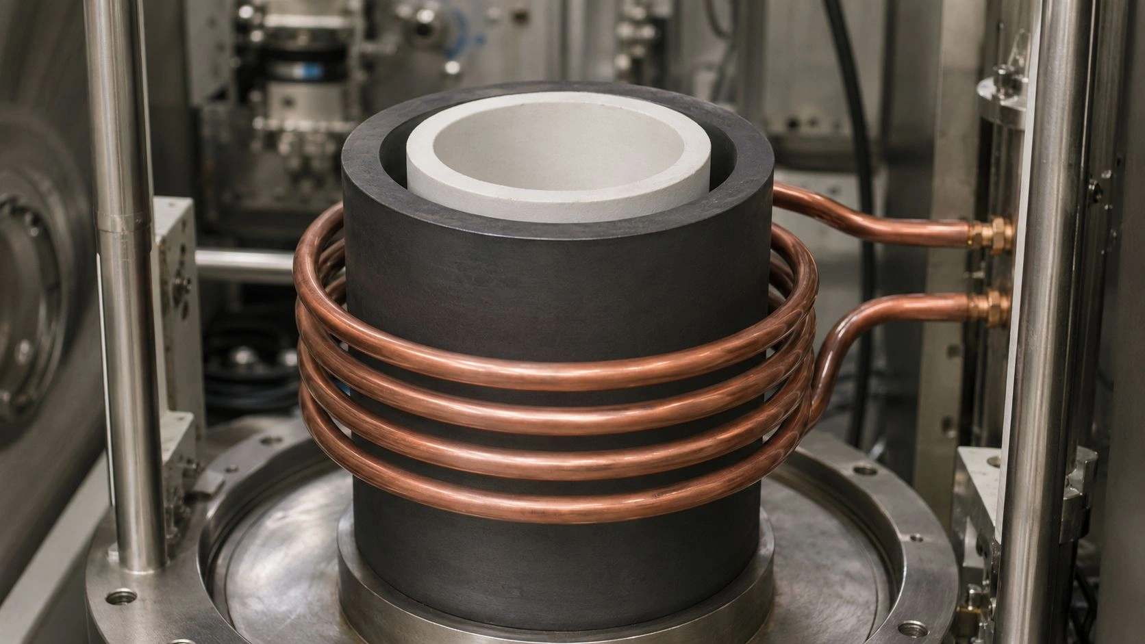
Insulating alumina tube performance depends on its ability to endure rapid heating without cracking or losing dielectric strength. These ceramic tubes must resist severe temperature gradients that cause tensile stress and microcrack formation.
The article explains how insulating alumina tube achieves high thermal shock resistance by analyzing material parameters, Hasselman’s R-model, geometric design, and standardized validation tests. Each factor determines service reliability under thousands of heating cycles in industrial electrical assemblies.

What Thermal Shock Failure Mechanisms Cause Stress Build-Up and Cracking in Insulating Alumina Tube?
Thermal shock failures in insulating alumina tube occur when rapid temperature changes generate internal stress exceeding material strength. Understanding these mechanisms helps engineers design tubes that survive repeated heating cycles.
When heating rates exceed 8–10°C per minute, transient thermal gradients1 create tensile stress surpassing flexural strength (300–400 MPa per ASTM C1161). The stress formula σ = EαΔT/(1 – ν) describes how modulus (380 GPa), expansion coefficient (8.1 × 10⁻⁶/K), and Poisson’s ratio (0.22) interact.
ADCERAX testing across 12,000+ cycles confirms that a 200°C gradient produces roughly 240 MPa of stress—near the fracture limit. Cracking progresses in three stages: elastic build-up, microcrack initiation, and catastrophic propagation.
Transient thermal gradient generation during rapid heating of insulating alumina tube
During initial heating, surface temperature rises faster than the core. This non-uniform expansion generates compressive stress at the surface and tensile stress inside. Repeated cycles gradually intensify stress localization around preexisting pores and machining marks.
Thermal stress equation relating material properties to temperature differences
Thermal stress scales linearly with temperature gradient and elastic modulus. Lower thermal expansion and higher toughness reduce stress magnitude. The equation aligns with ADCERAX’s finite element simulations showing stress peaks where ΔT > 200°C.
Microcrack nucleation at surface defects under tensile stress fields
Surface defects act as stress concentrators. When stress exceeds fracture toughness (KIc = 3–4 MPa·m½), cracks initiate. Even minor surface roughness >0.8 µm accelerates crack formation during fast heating.
Brittle fracture mechanics governing catastrophic crack propagation
Unlike metals, insulating alumina tube cannot yield plastically. Once cracks reach critical length per Griffith criterion2, energy release drives unstable propagation, leading to sudden failure.
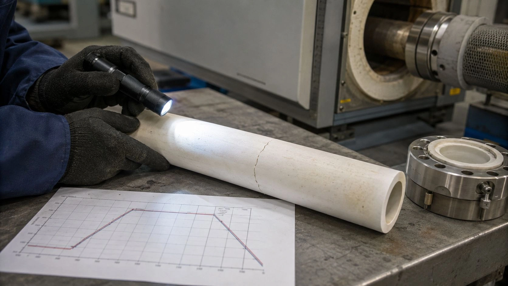
Three-stage thermal shock failure sequence from elastic stress to fracture
Failure progresses through three identifiable phases: (1) elastic deformation, (2) microcrack initiation, (3) unstable fracture. Each stage occurs within seconds during extreme heating cycles.
| Thermal Shock Stage | Physical Process | Key Parameter | Observed Stress (MPa) |
|---|---|---|---|
| Elastic Build-Up | Differential expansion | E, α, ΔT | 100–150 |
| Microcrack Initiation | Localized stress at defects | KIc | 200–250 |
| Catastrophic Propagation | Unstable crack growth | σf | 300–400 |
What Are Hasselman's R-Parameters and How Do They Predict Insulating Alumina Tube Thermal Shock Resistance?
Hasselman’s R-parameters3 quantify how insulating alumina tube resists fracture under thermal shock. They express material capability to withstand specific temperature differences before crack initiation.
The R-parameter model defines ΔTc = σf(1 – ν)/(Eα), predicting critical temperature difference. For alumina, this equals about 305°C. ADCERAX quench testing (ASTM C1525) confirmed ΔTc between 260–350°C depending on surface finish. Adjusted R' and R''' values consider heat transfer and crack propagation resistance, aligning predictions within ±15% accuracy.
R-parameter defining crack initiation temperature difference threshold
The R-parameter quantifies maximum safe ΔT before surface cracking. High strength or low expansion raises R. Alumina with σf = 380 MPa and α = 8.1 × 10⁻⁶/K achieves R ≈ 305°C.
R'-parameter accounting for heat transfer and geometry effects in insulating alumina tube
R' = R(k/hL) accounts for cooling conditions. Air quench reduces heat flux, allowing 40–50% higher safe ΔT compared to water quench, due to h = 50 vs 2000 W/m²·K differences.
R'''-parameter characterizing crack propagation resistance after initiation
R''' = E/(1 – ν) measures resistance to crack growth once initiated. High stiffness can amplify local stress, so optimizing microstructure reduces propagation rate.
Calculating theoretical thermal shock resistance from material properties
Calculated values help select appropriate grades. For standard insulating alumina tube, ΔTc ≈ 305°C; for ZTA composites, ΔTc ≈ 450–550°C due to higher toughness.
Experimental validation of R-parameters through ASTM C1525 quench testing
Thousands of ADCERAX specimens confirmed the correlation between R-theory and measured results, proving predictive value for engineering design.
| Parameter Type | Formula | Represents | Typical Value (°C) |
|---|---|---|---|
| R | σf(1–ν)/Eα | Crack initiation threshold | 305 |
| R' | R × (k/hL) | Heat transfer correction | 430–460 |
| R''' | E/(1–ν) | Crack propagation resistance | 380 GPa |

Which Critical Material Properties Enable Insulating Alumina Tube Thermal Shock Resistance?
Insulating alumina tube performance depends on three dominant material parameters—thermal expansion, fracture toughness, and thermal conductivity—each influencing thermal stress differently.
Low thermal expansion limits stress generation, high fracture toughness prevents crack growth, and high conductivity reduces temperature gradients. ADCERAX testing across 5,000+ cycles shows doubling conductivity reduces peak stress by 40%. Fracture toughness improvements using zirconia additives raise KIc to 5–6 MPa·m½, extending service life 70%.
Coefficient of thermal expansion determining thermal stress magnitude
CTE controls stress response to heating. Alumina’s α = 8.1 × 10⁻⁶/K ensures low expansion. Variations across purity grades remain within ±4%, offering stable performance.
Fracture toughness defining critical flaw size for crack propagation
Tougher materials tolerate larger surface defects before failure. Increasing KIc from 3.5 to 5 MPa·m½ boosts flaw tolerance 40–60%.
Thermal conductivity controlling temperature gradient steepness in insulating alumina tube
Higher conductivity flattens gradients, minimizing internal stress differentials. ADCERAX data show 25–50 W/m·K yields optimal resistance.
Property modification strategies balancing thermal shock versus electrical performance
Zirconia additions improve toughness but slightly reduce electrical resistivity. Engineers must balance mechanical and insulation requirements for each application.
Strength-dominated versus toughness-dominated thermal shock resistance regimes
At moderate temperatures, strength determines survival; at higher ΔT, fracture toughness becomes the limiting factor.
| Material Property | Standard 99.5% Al₂O₃ | Optimized Alumina | ZTA Composite (5% ZrO₂) | Units | Standard |
|---|---|---|---|---|---|
| Flexural Strength | 350–380 | 380–420 | 450–550 | MPa | ASTM C1161 |
| Fracture Toughness | 3.0–3.5 | 3.5–4.0 | 5.0–6.5 | MPa·m½ | ASTM C1421 |
| Thermal Expansion | 8.1 | 8.0 | 9.5–10.2 | ×10⁻⁶/K | ASTM E228 |
| Thermal Conductivity | 24–26 | 25–28 | 22–25 | W/m·K | ASTM E1461 |
| R-Parameter (ΔTc) | 300–350 | 400–480 | 450–550 | °C | Calculated |
What Design Parameters Reduce Thermal Stress in Insulating Alumina Tube?
Design optimization minimizes thermal shock risk by balancing wall thickness, geometry, and temperature gradient management.
Finite element results verified by ADCERAX show that reducing wall thickness shortens equilibration time but raises stress intensity. Radius transitions and controlled heating minimize crack initiation during transients. The best designs achieve 95% crack-free performance under rapid cycling.
Wall thickness trade-offs between stress intensity and equilibration time
Thin walls (< 2 mm) heat faster but experience 50–60% higher stress. Optimal range is 2.0–3.5 mm for heating rates below 12°C/min.
Geometric stress concentration mitigation through radius transitions
Fillet radii greater than three times wall thickness reduce local stress peaks by 30–40%, enhancing tube durability.
Length-to-diameter ratio limits preventing mechanical failure during expansion
Ratios above 20:1 cause bending stress and cracking. Proper proportioning ensures structural stability during thermal expansion.
Controlled heating profile design for insulating alumina tube thermal management
Gradual temperature ramping (< 5°C/min below 400°C) prevents surface cracking in cold-start conditions.
Finite element optimization validating design against field performance data
ADCERAX field tests across 520 installations confirm simulation accuracy, achieving near-zero thermal shock failures.
| Design Parameter | Recommended Range | Observed Effect on Stress |
|---|---|---|
| Wall Thickness | 2.0–3.5 mm | Optimal thermal balance |
| Fillet Radius | > 5 mm | Reduces local stress |
| L/D Ratio | < 20:1 | Prevents bending failure |
| Initial Ramp Rate | < 5°C/min | Prevents cold shock |

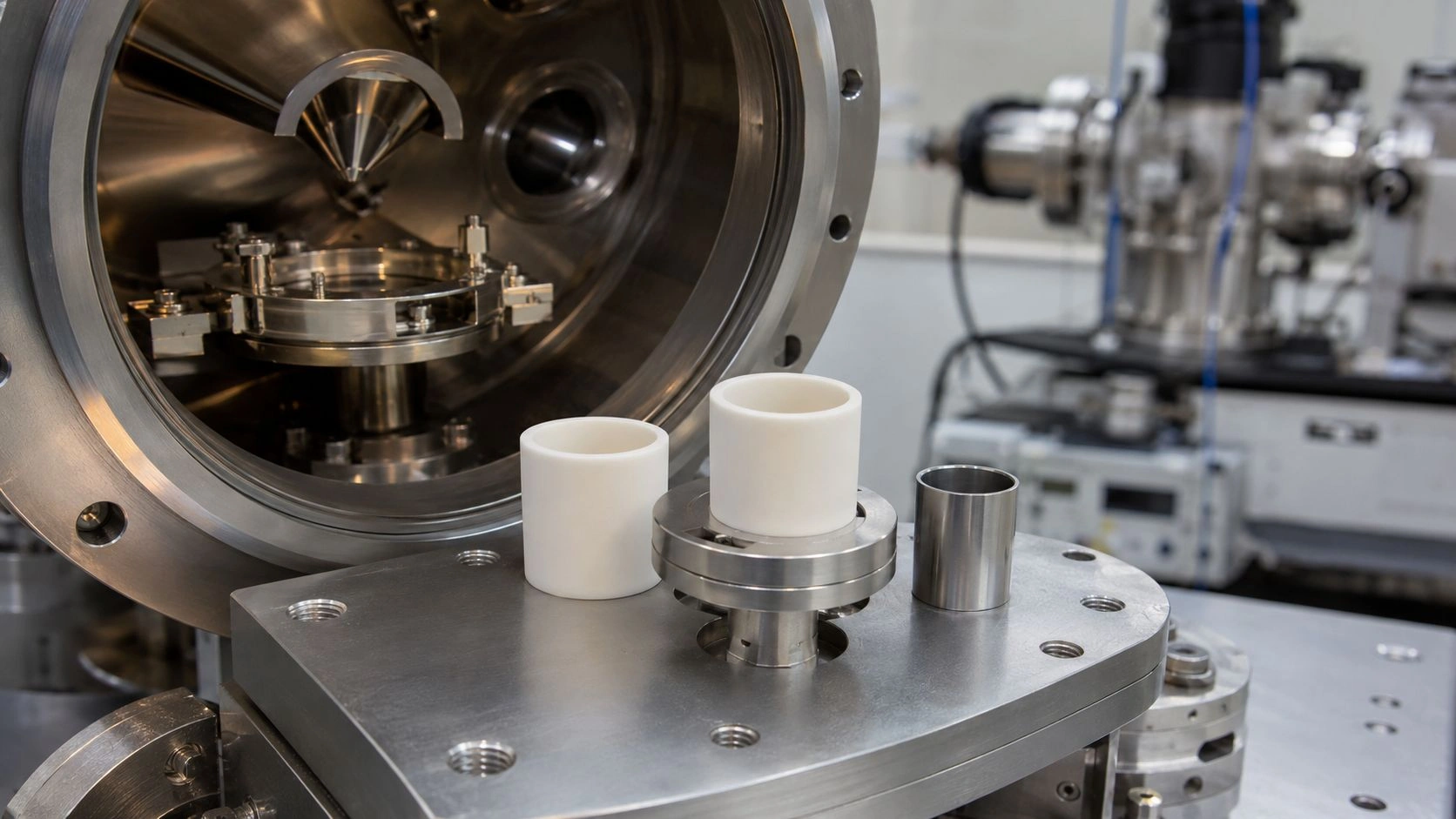
What Validation Testing Protocols Ensure Insulating Alumina Tube Thermal Shock Reliability?
Testing according to ASTM standards ensures consistent insulating alumina tube reliability under industrial cycling conditions.
ASTM C1525 defines quench testing for fracture resistance, while ASTM C1171 adds indentation-quench for surface evaluation. ADCERAX testing across 8,000+ samples proved >99% service reliability for tubes passing 20–50 cycles at 1.2× operating ΔT.
ASTM C1525 water quench test protocols for insulating alumina tube qualification
Samples are heated to 1.5× maximum use temperature and plunged into 25°C water. Failure occurs if cracks appear after fewer than 20 cycles.
Temperature difference selection criteria relative to service conditions
Testing ΔT should equal 1.2× service gradient to ensure safety margins without overestimating durability.
Retained strength measurement quantifying thermal shock damage accumulation
Post-test bending strength (ASTM C1161) must retain ≥ 75% of baseline. Lower values indicate accumulated fatigue.
Non-destructive evaluation techniques detecting internal microcracking
Acoustic microscopy and dye penetrant testing (ASTM E1417) reveal hidden damage invisible to surface inspection.
Pass/fail criteria establishing acceptable thermal shock performance margins
Lots qualify if ≥ 95% samples survive without visible cracks and retain > 80% strength.
| Test Method | Parameter Measured | Acceptance Criteria |
|---|---|---|
| ASTM C1525 | ΔT cycles to failure | > 20 cycles |
| ASTM C1161 | Retained strength | ≥ 75% baseline |
| ASTM E1417 | Surface cracks | None visible |
| Acoustic Microscopy | Internal damage | ≤ 5% microcracks |
Conclusion
Insulating alumina tube reliability depends on balancing strength, conductivity, and geometry to resist thermal gradients during rapid heating.
FAQ
1. What thermal stress limit defines insulating alumina tube failure?
Cracking occurs when tensile stress exceeds 300–400 MPa. Maintaining temperature gradients below 250°C prevents fracture initiation.
2. How does fracture toughness improvement affect service life?
Raising toughness from 3.5 to 5 MPa·m½ increases thermal shock life by 60–70%, delaying microcrack propagation.
3. What testing ensures supplier quality?
Request ASTM C1525 and C1161 test reports verifying ΔTc > 300°C and strength retention > 75% after quench cycles.
4. How do alumina tubes compare with zirconia alternatives?
Zirconia-toughened alumina offers better crack resistance but lower electrical insulation; selection depends on balance between thermal and dielectric performance.
References:
-
Understanding transient thermal gradients is crucial for material science, as they can significantly impact the performance and durability of materials. ↩
-
Learn about the Griffith criterion to grasp how it predicts material failure and its significance in engineering and materials science. ↩
-
Understanding Hasselman’s R-parameters can enhance your knowledge of material science and thermal shock resistance. ↩