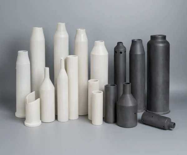
Ceramic Burner Tubes for Industrial Burners, Radiant Tubes, and Furnaces
ADCERAX reviews custom ceramic burner tube, radiant tube and flame tube projects for furnace, kiln, burner and heat-treatment systems. Each project is checked against the furnace type, combustion method, flame path, atmosphere, thermal cycle, tube geometry, end configuration and mounting interface before material selection.
– Alumina, silicon carbide and zirconia material routes for project review.
– Drawing-based OD, ID, wall, length, straightness, end and mounting features.
– RFQ review for new furnace projects, replacement parts and old-part failure cases.
What Is a Ceramic Burner Tube?
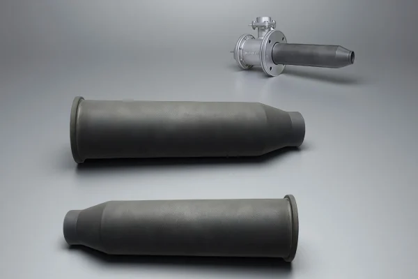
A ceramic burner tube is a tube-shaped ceramic component used around industrial burners, radiant heating paths, flame tubes, furnaces and kilns. It is different from an ordinary ceramic tube because the review must include combustion-system conditions such as flame position, hot-zone exposure, atmosphere, thermal cycling, tube support, cold-end mounting and replacement history.
ADCERAX reviews ceramic burner tube projects by matching the drawing and operating conditions to a suitable ceramic route. The review starts with furnace type, burner layout, atmosphere, temperature profile, thermal cycle, dimensions, end structure, mounting style and inspection requirements.
Failure Symptoms and Root-Cause Review for Ceramic Burner Tubes
Ceramic burner tube failures are rarely random. They often start at flame-impingement zones, hot-to-cold transition areas, or cold-end mounting interfaces where thermal cycling, oxidation, corrosive atmosphere, restrained expansion, or installation stress is concentrated.
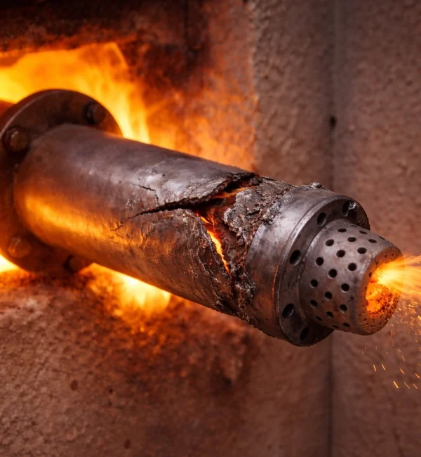
Use the table below to connect visible symptoms with possible root causes before selecting alumina, silicon carbide, or zirconia for a replacement or custom burner tube.
| Observable symptom | Likely root cause | What to check before material selection | RFQ data needed |
|---|---|---|---|
| Cracks near clamp, collar, or mounting end | Restrained expansion or mechanical stress at the cold end | Mounting method, expansion clearance, clamp force, cold-to-hot transition | Photos of failed end, mounting drawing, OD/ID, wall thickness, installation method |
| Spalling or roughening in the hot zone | Flame impingement, oxidation, corrosive gas, dust, or local hot spots | Flame path, atmosphere, contaminants, surface exposure, hot-zone temperature | Furnace/burner type, atmosphere, working temperature, photos of damaged surface |
| Long cracks after fast start-up | Thermal shock from rapid heating or cooling | Start-stop frequency, ramp rate, preheating process, temperature gradient | Heating cycle, ramp rate, shutdown pattern, material target |
| Ovality or dimensional drift | Metal tube creep, oxidation scaling, or ceramic tube overstress | Whether the current part is metal or ceramic, fit tolerance, support points | Existing material, target replacement size, straightness/tolerance requirement |
| Gas-side wear or erosion | Turbulence, particle impact, flame erosion, or aggressive combustion byproducts | Gas flow direction, dust/particle load, burner alignment, erosion area | Gas/media information, burner layout, failed part photos |
| Cracks at steps, shoulders, or transitions | Stress concentration at geometry changes | Radius, wall transition, grooves, shoulders, ports, machining design | Drawing, critical dimensions, tolerance, transition details |
Why Are Ceramic Materials Used for Burner Tubes?
Ceramic burner tubes outperform metal alloys through superior oxidation resistance, creep resistance, and thermal shock tolerance. Material selection matches ceramic properties to operating temperature, thermal cycling severity, and combustion atmosphere composition.
What Role Does Ceramic Play in Burner tube?
Ceramic tubes create a stable combustion chamber that maintains controlled flame geometry and prevents flame blow-off while isolating combustion from furnace atmospheres.
Ceramic materials transfer radiant heat at 1400-1700°C while maintaining dimensional stability. Alumina and SiSiC enable continuous operation without thermal degradation.
Chemically inert ceramic surfaces resist sulfur compounds, chlorides, and corrosive byproducts that rapidly degrade metal components, shielding sensors and mounting hardware.
Different Ceramic Burner Tube Material Options
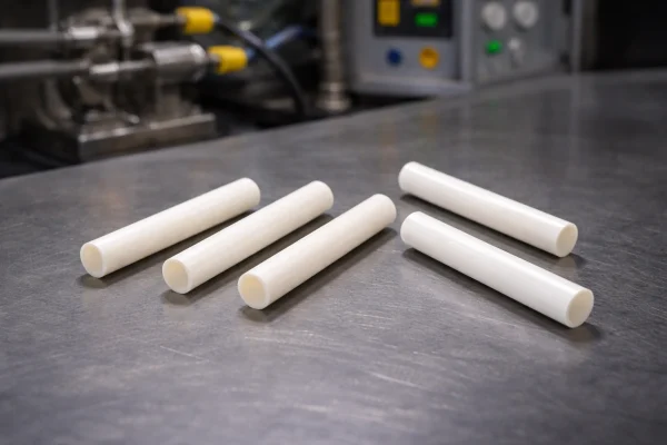
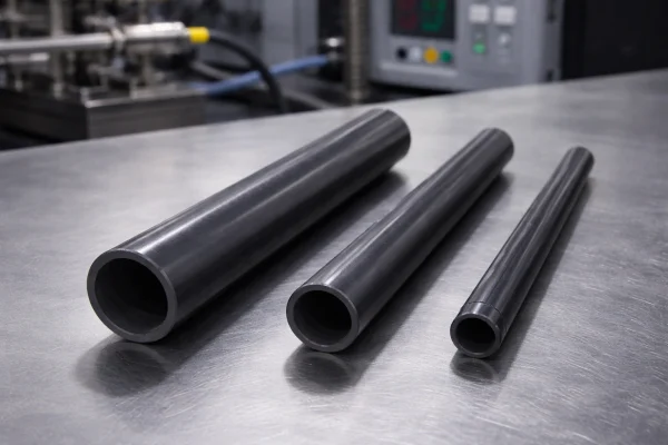
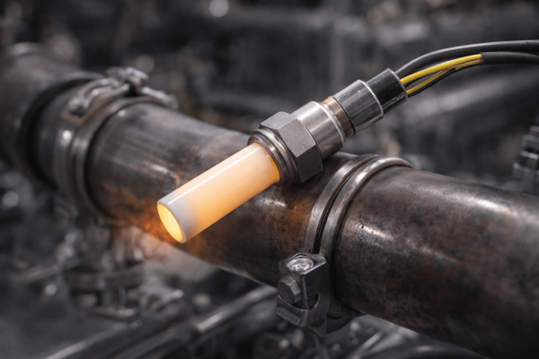
Higher fracture toughness for resisting crack initiation under cycling, with good stability in localized hot-spot regions.
How to Choose a Ceramic Burner Tube?
Material and design selection for ceramic burner tubes requires balancing interdependent thermal, mechanical, chemical, and geometric parameters. The following framework guides engineers through the decision process, highlighting critical trade-offs and application-specific priorities.
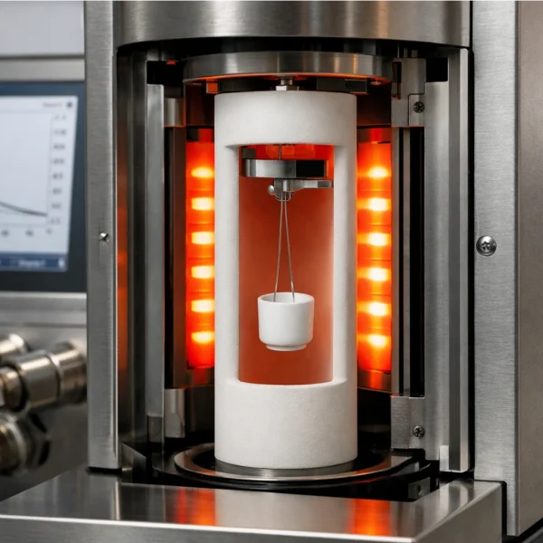
Key Selection Parameters
Engineers must evaluate these interdependent factors:
Temperature profile: Average setpoint plus local flame-impingement peaks.
Atmosphere: Excess air level, moisture, and contaminants (S/alkali/chlorides).
Thermal cycling: Start/stop frequency, ramp rate, and expected ΔT.
Geometry: OD/ID, wall thickness, straightness/ovality for high-aspect tubes.
Installation: Allow axial expansion; avoid misalignment and point clamping.
Ceramic Burner Tubes Material Comparison
| Material | Strengths in This Application | Limitations to Consider | Best-Fit Operating Conditions | Engineering Notes |
|---|---|---|---|---|
| High-alumina (≥99.5% Al₂O₃) | Oxidizing stability; strong shape retention | Lower thermal shock vs SiC; restraint-sensitive | High temp, controlled cycling | Uniform wall; allow axial growth; avoid hot spots |
| Zirconia (ZrO₂) | High toughness for cycling cracks; hot-spot tolerant | Low conductivity raises gradients | Severe cycling / hot spots | Add radii; avoid tight clamps; control ramps |
| Silicon Carbide (SiC) | High conductivity; strong shock resistance; impingement-ready | Oxidation window dependent | High heat flux / flame impingement | Control jetting; allow expansion; limit contaminants |
Typical Ceramic Burner Tube Configurations
Based on the engineering requirements outlined above, engineers typically select ceramic components in the following configurations. Each form factor addresses specific installation and performance needs.
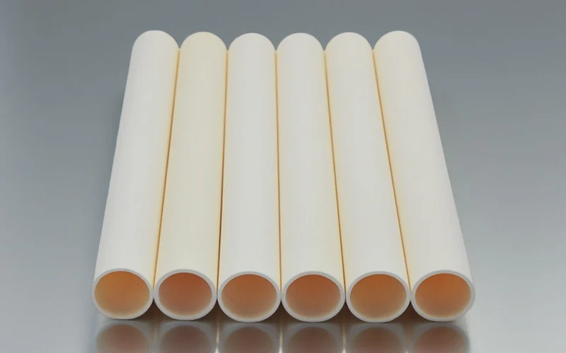
alumina ceramic burner tube
Stable geometry in oxidizing flames, with strong chemical resistance for long-term hot-zone service.
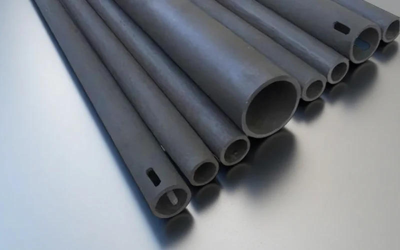
Silicon Carbide ceramic burner tube
Handles flame impingement and high heat flux, with fast heat spreading to reduce hot-spot cracking.
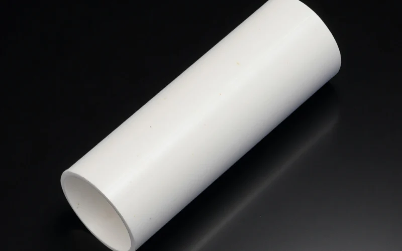
Zirconia ceramic burner tube
Higher fracture toughness for start-stop cycling, resisting crack initiation at hot-to-cold transition zones.
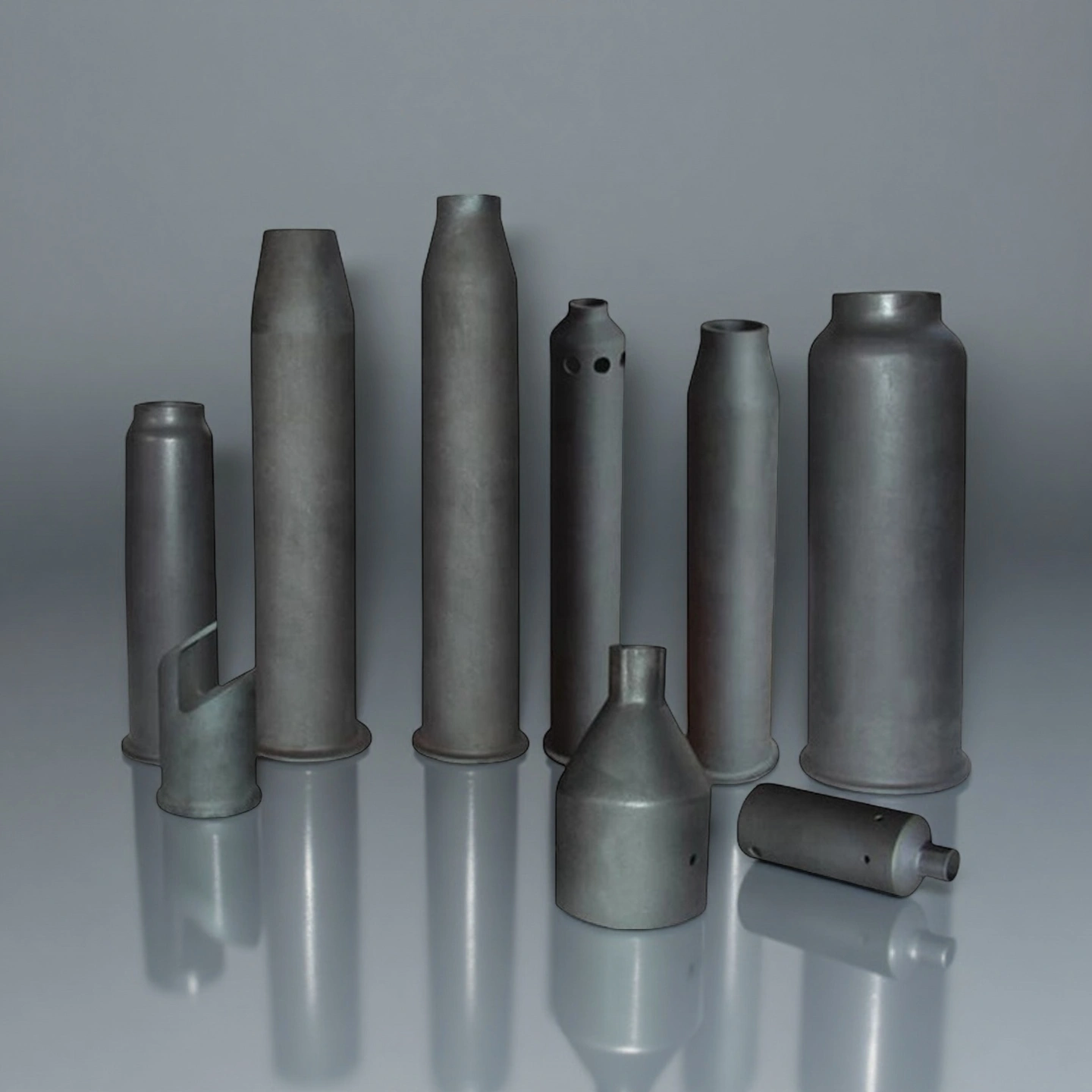
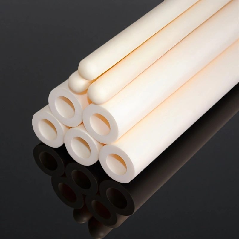
ceramic burner tube,Open-end
For through-flow mixing and flame guidance. Open-end design simplifies alignment in radiant-tube and direct-fired burner installs.
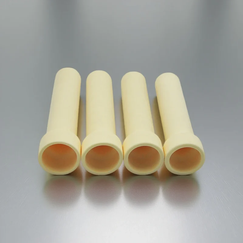
ceramic burner tube,Closed-end
For hot-gas isolation and controlled heat release. Closed-end tips reduce direct flame penetration in oxidizing cycling service.
Custom Ceramic Burner Tube Shapes
For fixed-depth mounting and sealing. Custom shoulders/tapers/flanges improve repeatable positioning and reduce clamp-stress cracking.
Ceramic Burner Tube Operating Scenarios
These ceramic burner components are deployed across multiple industries where high-temperature combustion stability, material longevity, and process reliability are critical to product quality and operational efficiency.
Steel and Metal Processing
Continuous annealing lines for steel strip: Operating at 800-1100°C in protective atmospheres (N₂-H₂ blends), ceramic radiant tubes contain combustion while radiating heat to the strip. Alumina or SiSiC tubes configured as U-tubes or W-tubes handle 50-100 thermal cycles annually.
Glass Manufacturing
Glass melting and forming furnaces: Combustion at 1400-1600°C with corrosive volatiles from batch materials. Mullite or high-purity alumina tubes resist alkali vapor attack and maintain dimensional stability, preventing ceramic particle contamination in glass products.
Industrial Boilers
Natural gas or oil combustion systems: Burner tubes resistant to thermal cycling from load following and startup/shutdown events. SiSiC handles thermal shock while alumina provides cost-effective solutions for base-load continuous operation.
Laboratory Research
Combustion research and materials testing: Custom ceramic burner tubes enable experimental control of combustion parameters and flame positioning. Precision-machined alumina tubes with specific internal geometries create repeatable flow conditions.
Cement and Lime Production
Rotary kiln burners: Extended length tubes (1000-2000mm) project into kiln hot zones above 1400°C surrounded by abrasive particulate and corrosive atmospheres. Mullite’s chemical inertness and crack tolerance address both chemical attack and mechanical impact.
Aerospace Heat Treatment
High-temperature furnaces for aerospace alloys: Precise temperature uniformity (±5-10°C) at 1200-1400°C in air or reducing atmospheres. Ceramic tubes prevent metallic contamination and maintain flame geometry over extended campaigns.
Custom Ceramic Burner Tube Options
Ceramic burner tube customization usually centers on hot-zone geometry and cold-end mounting or sealing features that manage thermal expansion. Sharing these parameters, along with your temperature profile and cycling conditions, allows a faster design review and reduces revision loops during sampling.
Custom Options Matrix
| Custom Parameter | Typical Specification | Why It Matters |
|---|---|---|
| Hot-zone geometry (OD, ID, wall thickness) | OD 15-120 mm; wall 2-10 mm typical | Controls heat flux, hot-spot risk, and thermal shock margin under flame impingement. |
| Length and straightness | Length 100-1500 mm; straightness ±0.5-2 mm per meter | Helps reduce misalignment, clamp stress, and uneven heating across the burner path. |
| End configuration | Open end, closed end, stepped end, tapered end | Defines flame or gas path behavior; steps and tapers can improve mounting stability. |
| Mounting interface features | Shoulder, groove, flange, collar land | Supports repeatable positioning and sealing while reducing restraint-driven cracking at the cold end. |
| Surface condition (ID/OD) | As-fired, ground, or polished in selected zones | Affects flow stability, sealing fit, and crack initiation risk at contact points. |
| Special ports or holes, if needed | Vent holes, relief holes, or sensor ports, case dependent | Supports pressure equalization, purge control, or integration with burner assemblies when required. |
FAQ About Ceramic Burner Tubes
It is used around industrial burners, radiant heating paths, flame tubes, furnaces, kilns, and heat-treatment equipment where tube geometry, material, atmosphere, flame path, and thermal cycling must be reviewed together.
ADCERAX can review alumina, silicon carbide, and zirconia routes for drawing-based burner tube projects. The selected route depends on furnace type, atmosphere, flame exposure, thermal cycle, dimensions, mounting, and inspection requirements.
No. A burner tube requirement needs combustion-system review, including flame path, hot-zone position, cold-end mounting, thermal stress, and atmosphere. Ordinary tube, protection tube, or insulating tube requirements should be reviewed under their own product routes.
Send drawings or dimensions, OD, ID, wall, length, straightness, end structure, mounting style, furnace type, combustion method, working temperature profile, atmosphere, thermal cycling, and photos of the old part or failure area if available.
Operating temperature needs project review because furnace temperature, flame hot spots, surface temperature, material route, atmosphere, and cycle pattern can be different. ADCERAX reviews the usable range after these details are provided.
ADCERAX can review these configurations when drawings or old samples define the geometry, tolerances, end features, mounting interface, and inspection points.
ADCERAX reviews the function first. Burner tube and radiant tube projects focus on combustion or radiant heating paths, burner nozzles focus on flame outlet geometry, and thermocouple protection tubes focus on sensor protection.
Ceramic Burner Tube RFQ Checklist
Include these with your drawing or old-part photo for a fast, accurate quote:
- Tube role: burner tube, radiant tube, flame tube, nozzle-related tube, or protection tube
- Material target: alumina, silicon carbide, zirconia, or request material review
- Dimensions: OD, ID, wall thickness, length, straightness, and end structure
- End configuration: open end, closed end, stepped, tapered, groove, flange, collar, or custom interface
- Operating conditions: working temperature, flame path, atmosphere, corrosion, dust, moisture, and thermal cycling
- Mounting details: cold-end support, clamp/collar area, expansion clearance, sealing surface, and installation constraints
- Failure symptoms if replacing: cracks, spalling, roughening, ovality, dimensional drift, hot-zone erosion, or mounting-end damage
- Quantity and project stage: sample, trial batch, maintenance replacement, or repeat production
A drawing, old burner tube photo, or failed-part reference is enough to start; material route, geometry, mounting details, and operating conditions will be confirmed during engineering review.
*Our team will answer your inquiries within 24 hours.
*Your information will be kept strictly confidential.
info@adcerax.com
Tel:+86-0731-84428843
WhatsApp:+86 19311583352
Within 24 hours