Ceramic Insulating Tube for Electrical Isolation in High-Temperature Furnaces and Heaters
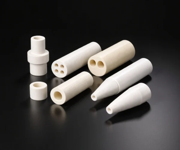
ADCERAX manufactures custom ceramic insulating tubes for thermocouples, heaters, furnaces and high-temperature electrical systems, including single-bore, multi-bore, closed-end and shaped designs.
With multiple technical ceramic material options and engineering support for custom bore layouts, dimensions and end features, we can review your drawing, dimensions or existing sample to evaluate manufacturability and recommend a suitable production route for your application.
What Is a Ceramic Insulating Tube?
A ceramic insulating tube is a hollow technical ceramic component that forms an electrical barrier around or between conductive parts. Its purpose is to maintain physical separation, reduce the risk of electrical leakage and prevent conductors from contacting nearby metal components.
Unlike conventional polymer insulation, ceramic does not soften or carbonize in the same way when exposed to heat. Its actual insulating performance depends on the ceramic material, wall thickness, bore spacing, surface condition, creepage distance, contamination and operating environment.
Problems with conventional insulating tubes
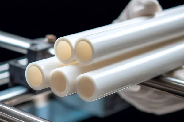
In high-temperature measurement and heating systems, electrical leakage and signal drift degrade thermocouple accuracy and compromise equipment reliability.
Metal sheaths, polymer insulators, and fibrous materials fail when exposed to temperatures above 800 °C or chemically reactive atmospheres. This leads to:
- Short circuits between conductors
- Erratic readings and measurement errors
- Unplanned shutdowns and production loss
Insulation breakdown leads to measurement errors, process deviations, increased scrap, and costly downtime.
Why do conventional insulating tubes fail in service?
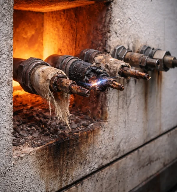
Conventional insulation materials fail in high-temperature electrical applications due to fundamental material limitations.
Understanding these failure mechanisms helps engineers select appropriate ceramic solutions and avoid recurring problems.
Thermal Degradation of Polymers and Organic Insulators
- Standard insulation materials lose dielectric strength and mechanical integrity above 300–500 °C
Oxidation and Chemical Attack
- Metal oxides form on unprotected conductors in oxidizing atmospheres, creating conductive paths and drift
Creep and Deformation Under Load
- Soft insulation materials sag or collapse at elevated temperatures, allowing conductor contact
Moisture Absorption in Porous Materials
- Fibrous insulators degrade rapidly when exposed to humidity or process gases
Thermal Expansion Mismatch
- Dissimilar materials expand at different rates, causing mechanical stress and insulation failure during thermal cycling
Why Are Ceramics Used for Insulating Tubes?
Ceramic insulator tubes are selected in this application for their ability to maintain electrical isolation under sustained high temperature while remaining dimensionally stable. Unlike organic or laminated insulation, dense technical ceramics retain high resistivity and structural integrity well above 1000 °C, depending on composition and atmosphere.
What role does ceramic play in high-temperature electrical insulation?
Ceramics keep high resistivity at temperature, so insulation stays predictable.
Ceramics resist softening and creep, maintaining gaps and alignment.
Dense ceramic barriers reduce leakage current and surface tracking.
Ceramics resist hot-zone vapors and dust that degrade insulation.
Ceramic Materials for Insulating Tubes
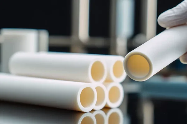
Provides stable dielectric performance and mechanical rigidity over a wide temperature range.
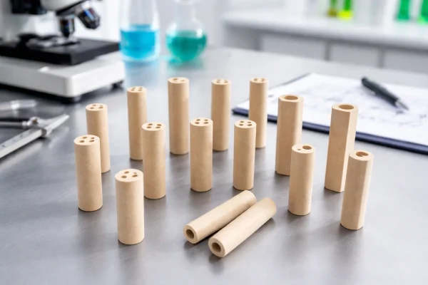
Offers very high electrical resistivity at elevated temperature
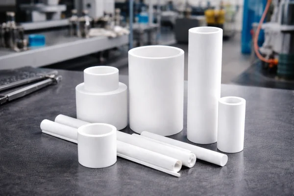
Offers lower thermal conductivity and better thermal shock resistance for rapid temperature swings
How to Choose a Ceramic Insulating Tube?
Selecting the right ceramic insulating tube requires matching material properties and geometric specifications to your operating conditions. The following outlines the critical parameters engineers need to consider and provides a material comparison framework to guide selection decisions.
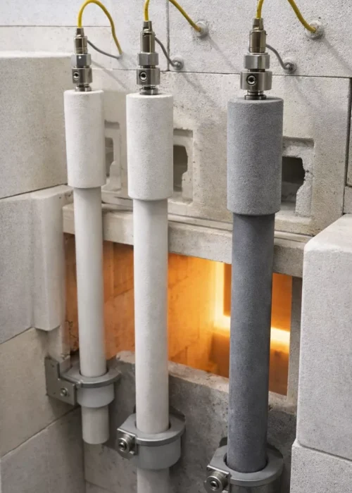
Key Selection Parameters
Consider the following parameters when specifying ceramic insulating tubes:
Define maximum continuous and peak excursion temperatures; select alumina purity or alternative ceramic accordingly
Identify oxidizing, reducing, neutral, or vacuum conditions; some ceramics are atmosphere-sensitive
Specify required dielectric strength and leakage current limits at operating temperature
Determine number of holes, hole diameter, hole spacing, and positional tolerance for wire clearance
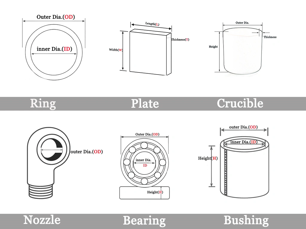
Confirm outer diameter, wall thickness, length, straightness, and end-finish requirements to ensure proper fit and alignment
Ceramic Insulating Tube Material Comparison
| Material | Strengths | Limitations | Best-fit Conditions | Notes |
|---|---|---|---|---|
| Alumina (Al₂O₃) | Stable dielectric behavior, good stiffness, broad availability | Brittleness under impact | Continuous electrical insulation above ~1000 °C | Widely specified for multi-bore insulators |
| Magnesia (MgO) | Very high resistivity at elevated temperature | Higher cost, handling sensitivity | Extreme-temperature electrical isolation | Often selected when insulation margin is critical |
| Zirconia (ZrO₂) | High fracture toughness, handling robustness | Lower max temperature than alumina | Mechanically demanding installations | Used where vibration or assembly stress exists |
Ceramic Insulating Tube Products
Ceramic insulating tubes provide electrical isolation and stable conductor spacing at high temperature. Common forms include single-bore, two-bore, and multi-bore tubes, plus cut-to-length or ground-finish parts. Material and geometry are set by temperature, voltage, and clearance needs.
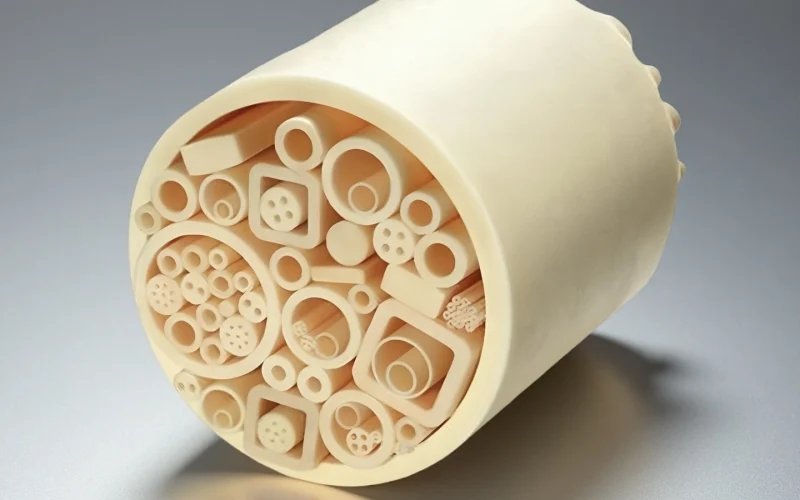
alumina ceramic insulator tube
High electrical insulation and chemical stability for low drift protection.
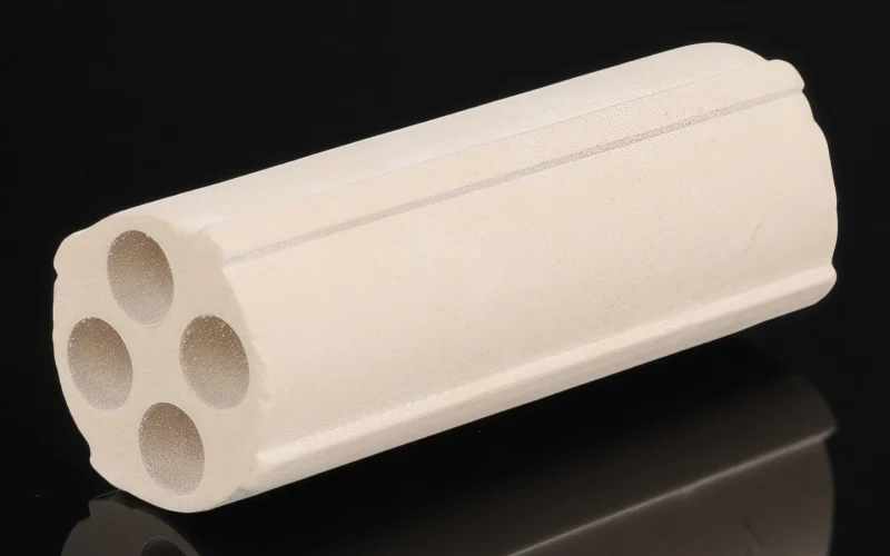
Magnesia ceramic insulator tube
High-temperature insulation for heater assemblies; review moisture exposure.
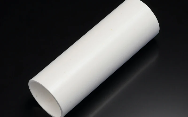
Zirconia ceramic insulator tube
Low thermal conductivity and high toughness for demanding assemblies.
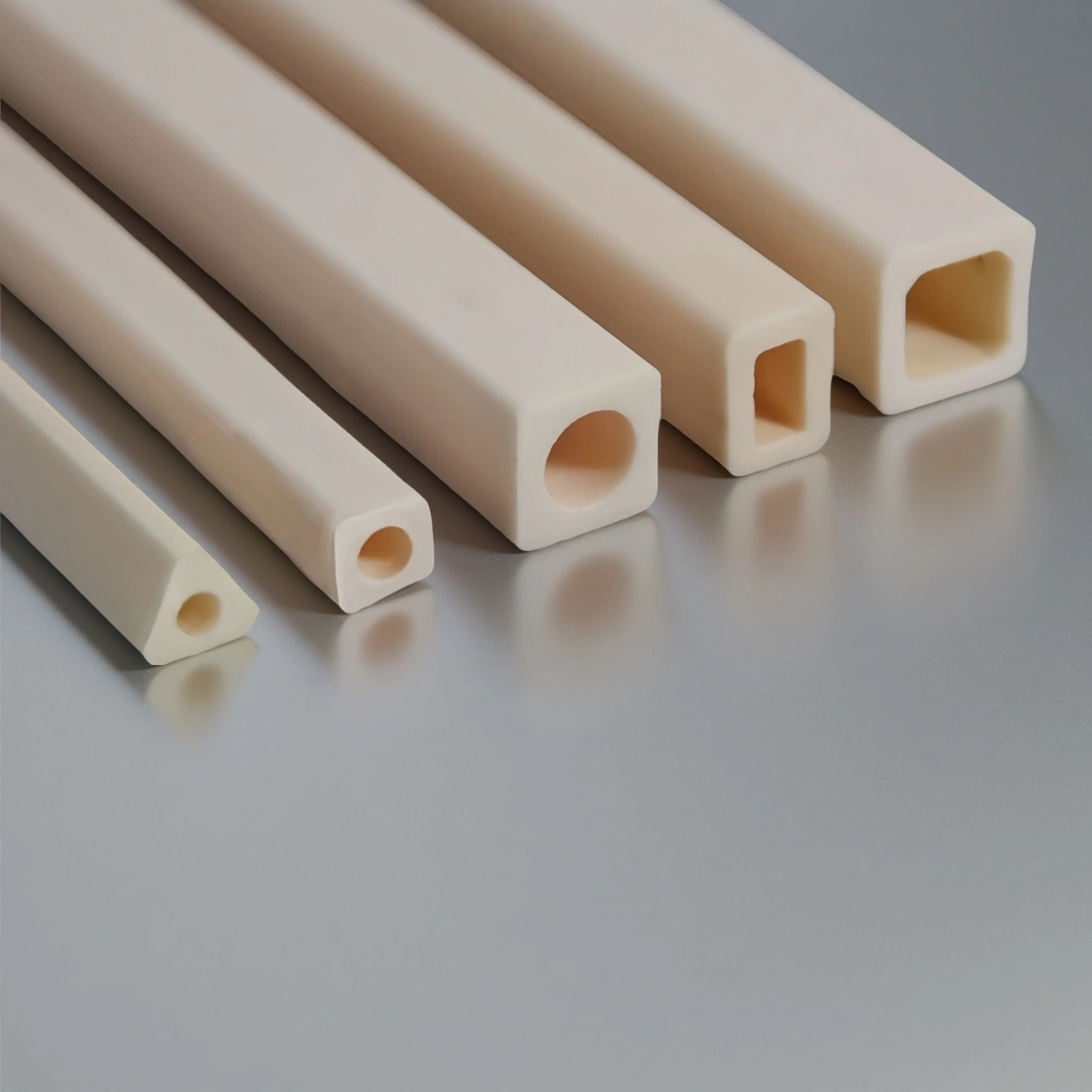
Square ceramic insulating tube
For constrained mounts and fixed-orientation requirements. Square profile prevents rotation and improves alignment.

Multi-Bore ceramic insulating tube
For multi-element probes and drift-sensitive control loops. Separated bores improve insulation and reduce cross-talk.
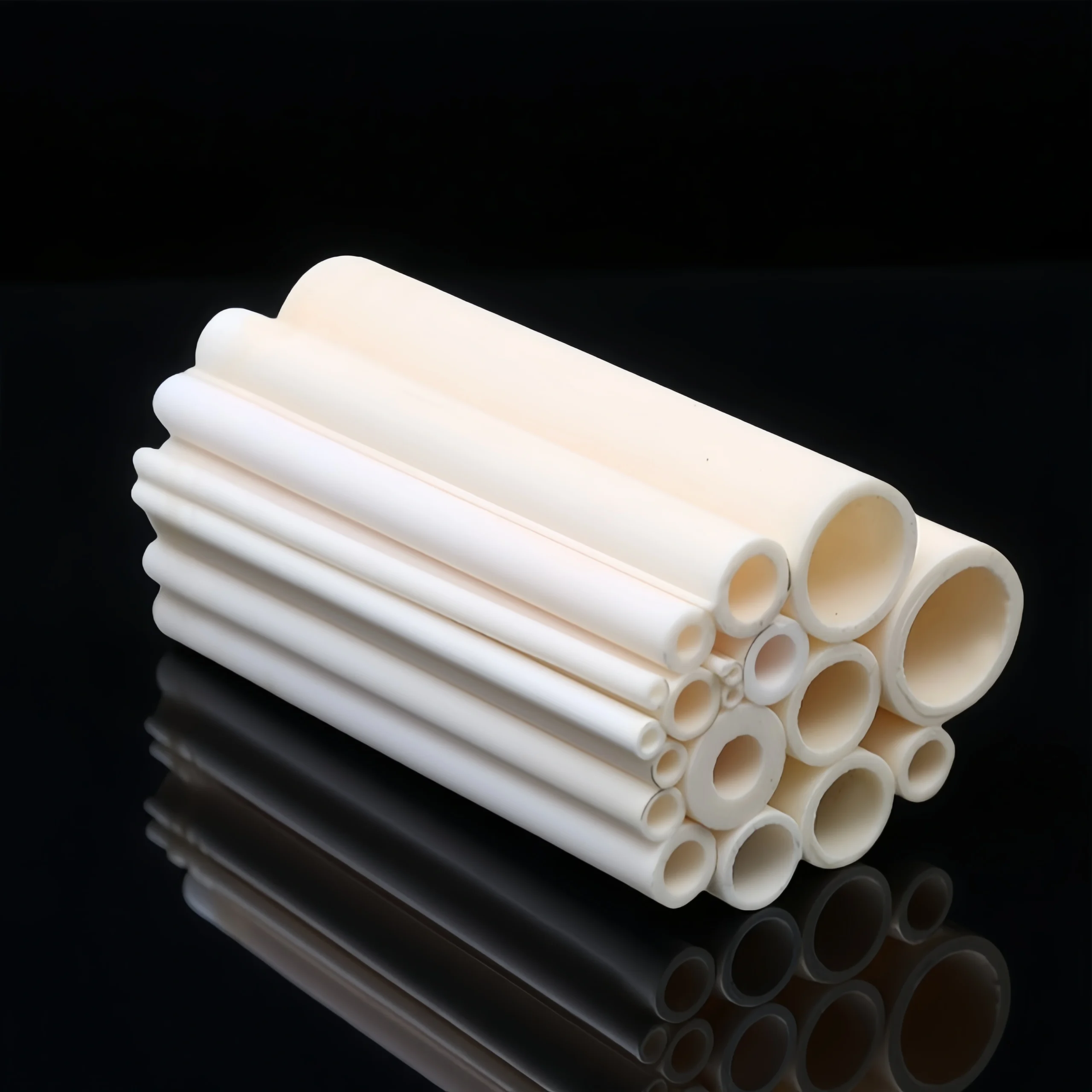
ceramic insulator tube,Open Both Ends
For guided furnace installs and frequent probe replacement. Open-through design enables fast insertion and easy maintenance.
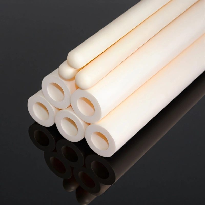
ceramic insulation tube,One End Closed
For corrosive atmospheres and drift-sensitive temperature control. Closed tip isolates the hot junction to reduce contamination exposure.
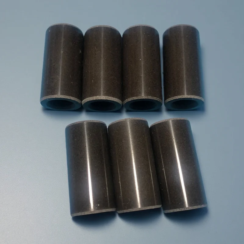
Black ceramic insulating tube
For threaded ports requiring adjustable insertion depth. Threaded mounting locks position with repeatable adjustment.
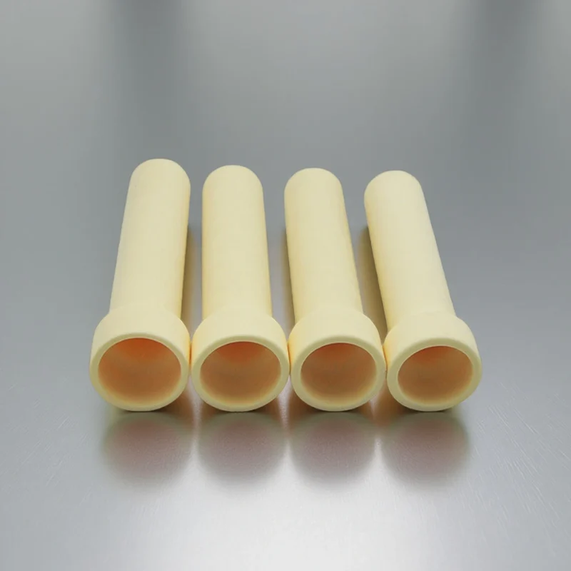
ceramic Shaped Bore Insulating Tube
For assemblies requiring fixed conductor positioning. Shaped bores guide wires and match non-round features.
Ceramic Insulating Tube Applications
Ceramic insulating tubes serve multiple high-temperature electrical insulation roles across industrial heating, measurement, and processing equipment. Common applications where ceramic insulators maintain electrical isolation, prevent signal drift, and extend service life:
Thermocouple Assemblies for Industrial Furnaces
Multi-bore tubes isolate Type K, Type N, Type R, or Type S thermocouple wires in heat treatment, annealing, and sintering furnaces operating continuously above 1000 °C
Temperature Measurement in Kilns and Dryers
Single-bore or twin-bore insulators protect sensor wires in ceramic firing kilns, rotary calciners, and high-temperature dryers where chemical vapors or particulates are present
High-Temperature Test and Calibration Equipment
Precision-grade alumina tubes provide stable electrical isolation in temperature calibration furnaces and materials testing rigs where measurement accuracy and repeatability are critical
Metal Processing and Heat Treatment Lines
Twin-bore and multi-bore tubes enable multi-zone temperature profiling in continuous annealing lines, wire drawing furnaces, and aluminum or steel heat treatment systems
Electric Heater Assemblies
Insulating tubes separate power leads or control wiring from grounded metallic heater housings in cartridge heaters, band heaters, and immersion heaters
Laboratory Tube Furnaces
Standard-length insulating tubes support thermocouples in horizontal and vertical tube furnaces used for materials research, catalyst testing, and CVD processes
Common Failure Modes and Mitigation
Ceramic insulation tubes fail when operating conditions exceed material limits or design parameters are mismatched. Identifying failure mechanisms helps engineers select appropriate materials, tolerances, and installation methods to prevent premature failure.
| Symptom | Likely Cause | Design / Material Adjustment | Notes |
|---|---|---|---|
| Electrical leakage | Insulation resistivity drops at temperature | Switch to higher-purity alumina or magnesia | Verify resistivity at operating temperature |
| Cracking during operation | Rapid heating or constrained expansion | Review heating rate, wall thickness, and mounting clearance | Avoid rigid mounting and steep thermal gradients |
| Chipping at ends | Handling or installation stress | Add chamfer or use tougher material | Zirconia may reduce handling damage |
| Short circuits | Insufficient clearance or creepage | Increase bore spacing or tube length | Review voltage and layout assumptions |
| Misalignment | Creep or fixture movement | Improve mechanical support strategy | Avoid over-constraining ceramic parts |
Custom Ceramic Insulating Tube Options
Engineers often require dimensional or geometric modifications beyond standard catalog offerings to match specific conductor layouts, installation constraints, or thermal environments. The following customization options address the most common application-driven requirements:
Custom Options Matrix
| Custom Parameter | Typical Specification | Why It Matters |
|---|---|---|
| Bore configuration | Single-bore, twin-bore (2-hole), multi-bore (4-hole, 6-hole, 8-hole) | Matches conductor count and separation requirements; prevents short circuits and signal interference |
| Outer diameter and wall thickness | OD 3–25 mm, wall 0.5–5 mm typical | Ensures mechanical strength and proper fit in mounting hardware or protection tubes |
| Length and straightness tolerance | 50–2000 mm length; straightness ±0.5–2 mm per meter | Long tubes require tighter straightness control to avoid bending stress and installation difficulty |
| Hole diameter and positional tolerance | ID 0.5–10 mm; hole spacing ±0.1–0.3 mm | Tight tolerances prevent wire contact and maintain consistent electrical isolation |
| End finish | As-fired, chamfered, one-end closed, ground flat | Affects ease of installation, sealing performance, and breakage risk during handling |
| Surface finish | As-fired, ground OD/ID, polished | Ground or polished surfaces improve dimensional consistency and fitting tolerance |
FAQ about Ceramic Insulating Tube?
Do not select the material by temperature alone. The main factors are:
- Operating temperature and thermal cycling
- Voltage and creepage requirements
- Atmosphere, moisture and contamination
- Mechanical load and bore geometry
Not necessarily. Wall thickness can increase the physical separation between conductors, but insulation performance also depends on the ceramic material, bore spacing, creepage distance, surface condition, contamination and operating environment. An unnecessarily thick wall may also affect assembly fit, heat transfer and thermal stress.
Common causes include rapid temperature changes, restricted thermal expansion, excessive installation force, misalignment, vibration and mechanical contact with surrounding components. Cracking may result from the tube geometry or mounting method rather than the ceramic material alone. The complete assembly should therefore be reviewed when repeated failures occur.
Suitability depends on the ceramic material, temperature, gas composition, moisture level, contaminants and exposure duration. A material that performs well in one atmosphere should not automatically be assumed suitable for another. Please provide the actual operating environment before the material is confirmed.
Provide the normal and peak operating voltage, AC or DC condition, frequency where relevant, required clearance or creepage distance, conductor arrangement and surrounding environment. Any applicable insulation test, leakage limit or industry standard should also be identified before the tube design is finalized.
Yes, an initial review can begin with clear photos of the existing part, overall length, OD, ID, bore layout, end features, required quantity and application conditions. A physical sample or a more complete dimensional drawing may still be required before manufacturing feasibility and tolerances can be confirmed.
Manufacturability depends on the ceramic material, tube length, bore diameter, bore spacing, wall thickness, straightness requirement and dimensional tolerances. These features must be evaluated together because improving one dimension may affect another. A drawing review is required before a production route can be recommended.
Critical dimensions should first be identified according to assembly fit and electrical function. Ceramic forming, firing shrinkage, tube length and any required post-firing machining can all affect the achievable tolerance. ADCERAX reviews the drawing and marks dimensions that require engineering confirmation before quotation.
Ceramic Insulating Tube RFQ Checklist
Send the available details below for engineering review and quotation:
- Application: thermocouple, heater, furnace, feedthrough, or replacement part
- Tube design: single-bore, multi-bore, open-ended, one-end-closed, or shaped
- Material: preferred ceramic or request material support
- Working conditions: temperature, voltage, atmosphere, and thermal cycling
- Dimensions: OD, ID, bore count, hole spacing, length, and end features
- Key requirements: tolerances, straightness, mounting, or inspection
- Quantity: prototype, trial batch, or repeat order
A drawing is preferred, but a sketch, sample photo, or existing part can also be reviewed.
*Our team will answer your inquiries within 24 hours.
*Your information will be kept strictly confidential.
info@adcerax.com
Tel:+86-0731-84428843
WhatsApp:+86 19311583352
Within 24 hours