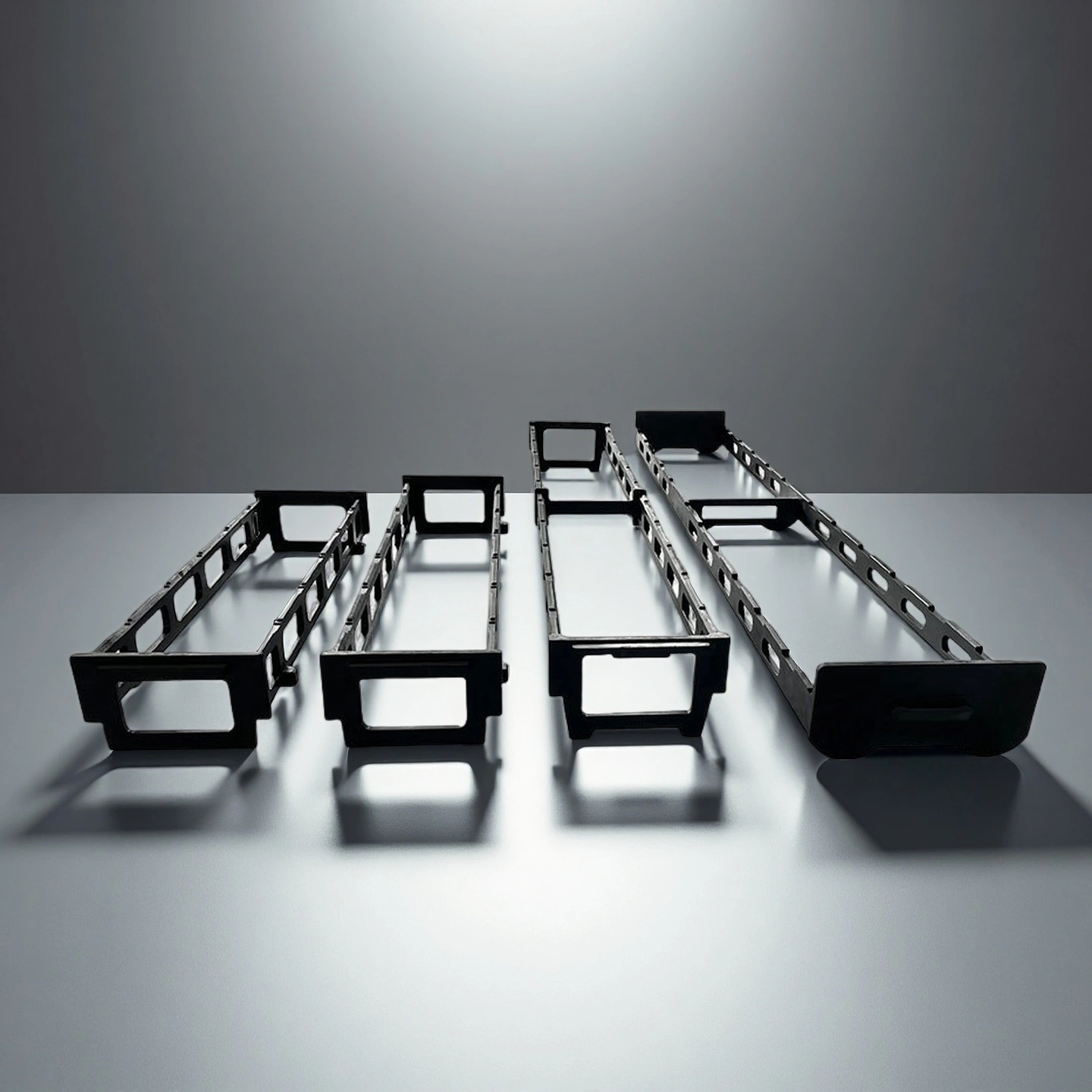
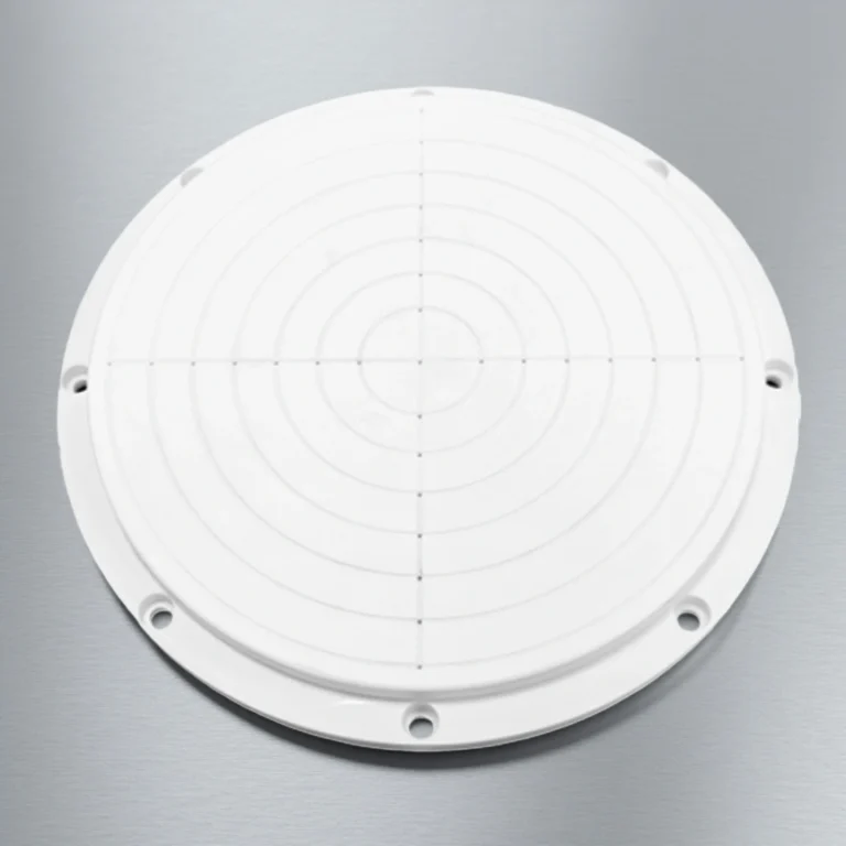
Uniform-Thermal Silicon Carbide Boat Bracket for PV High-Temperature Lines
The Silicon Carbide Boat Bracket delivers reliable structural performance in demanding furnace environments by maintaining alignment, heat uniformity, and long-cycle mechanical endurance across wafer-handling operations.
Catalogue No.
AT-SIC-T1001
Material
RBSiC or SSiC engineered for high-temperature structural stability
Thermal Performance
Thermal conductivity 120–160 W/mK supporting uniform heat distribution
ADCERAX® Silicon Carbide Boat Bracket is engineered for wafer-handling furnace environments that require stable support, controlled thermal behavior, and consistent structural performance. Its role aligns with the operational demands of diffusion, oxidation, and annealing systems, where maintaining uniform heat flow and reliable alignment is essential for SiC Boat Holder and Silicon Carbide Boat Support assemblies. By combining high mechanical rigidity with a microstructure designed for long-cycle thermal processing, the bracket enables predictable wafer positioning and dependable performance across semiconductor, photovoltaic, and advanced materials applications.
Key Features of Silicon Carbide Boat Bracket
Low expansion behavior for stable carrier alignment The material’s thermal expansion coefficient remains within 4.0–4.5 × 10⁻⁶/K, enabling predictable fit with Silicon Carbide Boat Support structures. Its dimensional consistency minimizes drift during cycles that typically exceed 1000°C in semiconductor and PV environments.
Fatigue endurance enabling thousands of cycles Creep strain remains below 0.5% after 1000 hours at 1500°C, minimizing material fatigue during long thermal campaigns. This endurance supports continuous-day furnace schedules common in PV and semiconductor process lines.
Surface finish optimized to Ra 1.2–3.2 μm This surface profile reduces friction during boat loading and unloading, and minimizes particulate generation by more than 35%, supporting high-purity processing workflows. It also ensures predictable interaction with SiC Wafer Boat Holder interfaces.
Technical Specifications of Silicon Carbide Boat Bracket
ADCERAX® Silicon Carbide Boat Bracket demonstrates stable mechanical behavior, controlled thermal response, and consistent microstructural reliability under extended high-temperature furnace conditions, enabling predictable performance in wafer-handling environments.
Property
Specification
Flexural Strength (RBSiC)
200–260 MPa
Flexural Strength (SSiC)
350–450 MPa
Compressive Strength
≥1800 MPa
Young’s Modulus
300–420 GPa
Thermal Conductivity
120–160 W/mK
Thermal Expansion Coefficient
4.0–4.5 × 10⁻⁶/K
Maximum Operating Temperature
1500–1700°C
Thermal Shock Resistance
>300°C/min
Density (RBSiC)
2.60–2.70 g/cm³
Density (SSiC)
3.10–3.15 g/cm³
Open Porosity (RBSiC)
10–20%
Hardness (SSiC)
Mohs > 9.2
Creep Rate at 1500°C
<0.5% after 1000 h
Surface Roughness (Ra)
1.2–3.2 μm
Atmospheric Compatibility
Stable in O₂/N₂/H₂/Ar
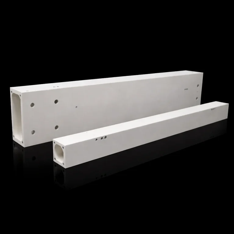
Dimensions of Silicon Carbide Boat Bracket
Silicon Carbide Boat Bracket
Item No.
Diameter(mm)
Height (mm)
AT-SIC-T1001
Customize
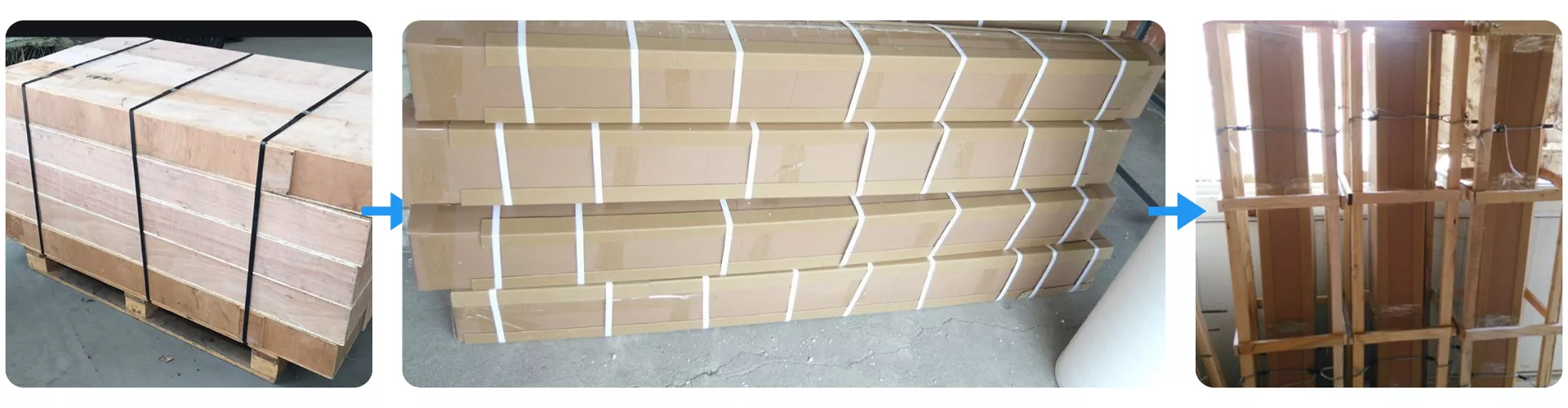
Packaging Method for Silicon Carbide Boat Bracket
Silicon Carbide Boat Bracket is packed using reinforced cardboard cartons combined with internal cushioning to stabilize each component during international transport. Each carton is further consolidated into wooden crates or palletized structures to prevent vibration and impact throughout long-distance shipping. This packaging method ensures safe delivery for all furnace-grade SiC components, supporting reliable handling and protected storage upon arrival.
The Silicon Carbide Boat Bracket plays a direct role in stabilizing wafer carriers, maintaining uniform temperature fields, and preventing drift or deformation during PV cell diffusion, oxidation, and high-throughput annealing cycles. Photovoltaic production lines rely on consistent heat distribution, long-cycle mechanical endurance, and chemical inertness, and this component directly addresses those engineering challenges through its material characteristics and stable thermal behavior.
Silicon Carbide Boat Bracket in POCl₃ Diffusion Tubes for PV Cell Doping
✅Key Advantages
1. Heat-profile stability across the boat span In POCl₃ diffusion tubes, the ADCERAX® Silicon Carbide Boat Bracket keeps temperature deviation along the boat interface within ±3°C during extended high-temperature soaks. This stability reduces sheet-resistance spread across wafers, bringing Rs variation below 5% in many production conditions.
2. Controlled flatness under long soaking cycles Under repeated phosphorus diffusion campaigns, out-of-plane deviation of the bracket surface typically remains within 0.05–0.15 mm after several hundred cycles. This level of stability helps maintain boat levelness and limits dopant-profile differences between edge and center wafers to less than 3–4%.
3. Creep-resistant support for high wafer loads With a creep strain of less than 0.5% after 1000 h at 1500°C, the bracket preserves its geometry even when loaded with stacked wafer carriers. This endurance allows POCl₃ lines to run long campaigns without frequent support replacement, sustaining consistent electrical activation over thousands of processed wafers.
✅ ️Problem Solved
A PV cell producer operating POCl₃ diffusion tubes observed unstable sheet resistance where bracket distortion caused boat tilt over long campaigns. After approximately 300–400 furnace cycles, their existing supports showed visible bowing and produced Rs non-uniformity exceeding 8–10% across some runs. By switching to the ADCERAX® Silicon Carbide Boat Bracket with controlled flatness and creep-resistant RBSiC/SSiC, levelness deviation was kept within the 0.05–0.15 mm range. As a result, the line reported a reduction in Rs spread to around 4–5%, leading to more predictable phosphorus diffusion and improved batch-to-batch repeatability.
Silicon Carbide Boat Bracket in Boron Diffusion Lines for P-Type Emitter Formation
✅Key Advantages
1. Surface integrity in reactive BCl₃ atmospheres The ADCERAX® Silicon Carbide Boat Bracket maintains structural integrity after more than 500 boron diffusion cycles in BCl₃-containing atmospheres without measurable spalling. Post-run inspections show surface roughness remaining within Ra 1.2–3.2 μm, limiting new particle generation that could disrupt the doping environment.
2. Stable wafer positioning during rapid thermal ramps When subjected to thermal ramps above 300°C/min, the bracket retains its stiffness and alignment behavior, preventing micro-shifts in wafer position during critical segments of the diffusion profile. This stability helps keep emitter sheet-resistance sigma within 3–4%, even under aggressive process recipes.
3. Reduced particle contribution to emitter defects Particle monitoring in boron lines using this bracket demonstrates a noticeable reduction in process-related fallout, with counts in critical size ranges lowered by more than 30% compared with lower-grade supports. This reduction translates into fewer surface defects attributed to support-origin contamination during P-type emitter formation.
✅ ️Problem Solved
A manufacturer running high-volume boron diffusion reported recurring emitter defects traced to particle contamination from degraded support components. Over time, their existing supports roughened in the BCl₃ atmosphere, and particle counters recorded elevated counts during long campaigns, correlating with increases in defective cells and widened emitter sheet-resistance distribution. After introducing the ADCERAX® Silicon Carbide Boat Bracket, post-diffusion audits showed a particle-count reduction of over 30% in the relevant size range and a tighter Rs sigma, falling to around 3–4%. This change stabilized P-type emitter quality and reduced process interruptions caused by unplanned furnace cleaning.
Silicon Carbide Boat Bracket in High-Throughput PV Annealing and Gettering Lines
✅Key Advantages
1. Rigidity against vibration-induced misalignment In continuous annealing and gettering lines, the ADCERAX® Silicon Carbide Boat Bracket uses a high modulus in the 300–420 GPa range to resist vibration from conveyors and robotic handlers. This stiffness limits positional drift of wafer carriers to less than 0.1 mm over extended operating periods, supporting consistent handling geometry.
2. Geometry retention over long operating schedules Even in lines running more than 18–20 hours per day, warpage of the bracket remains tightly controlled, with bow kept within 0.05–0.15 mm after extended use. This stability contributes to a reduction in wafer bow variation by more than 20%, improving downstream lamination and module assembly consistency.
3. Support for stable gettering effectiveness By maintaining repeatable carrier alignment and flatness, the bracket helps keep thermal exposure and stress distribution uniform during gettering. Process monitoring has shown more consistent lifetime-improvement metrics across wafers, with variation in key gettering indicators reduced by around 15–25% when compared to runs using less rigid supports.
✅ ️Problem Solved
A PV producer operating high-throughput annealing lines observed that wafer bow and gettering results drifted over multi-week campaigns, particularly on lines with older support structures. Vibration and thermal cycling gradually altered carrier alignment, and measurements indicated increased bow dispersion and less stable lifetime-improvement values. After retrofitting the line with the ADCERAX® Silicon Carbide Boat Bracket, positional drift was held below 0.1 mm, and bow variation decreased by more than 20% over comparable operating periods. At the same time, internal monitoring showed a narrower distribution in gettering-related performance indicators, confirming that improved structural stability translated into more predictable annealing outcomes.
How to Use the ADCERAX® Silicon Carbide Boat Bracket for Stable and Predictable Furnace Operation
The Silicon Carbide Boat Bracket is designed for long-cycle thermal processing environments, and proper handling practices help maintain its structural consistency, alignment accuracy, and operational lifespan in PV diffusion, annealing, and high-temperature workflows.
Pre-Operation Handling and Inspection Guidelines
1. Visual inspection should be performed before each production cycle to confirm that the support surfaces remain free of chips, micro-cracks, or visible distortion. Any irregularity can alter boat contact geometry, and this may influence heat-field distribution inside the furnace. Routine checks ensure that the component enters the process in a stable mechanical condition.
2. Contact regions must be clean and free of residual furnace dust or dopant deposits, as these layers can create uneven thermal contact. Even minor surface buildup can shift the bracket’s support behavior and influence wafer carrier levelness. Regular cleaning with non-abrasive tools helps maintain predictable interface performance.
3. When transferring the bracket between workstations, operators should use padded supports to prevent point-loading impacts. Sudden mechanical shocks may produce internal stresses that later emerge as thermal fatigue. Gentle handling preserves the microstructure’s stability during high-temperature cycling.
Installation Practices for Consistent Furnace Integration
1. During placement, alignment with the furnace’s loading rails or support frames must remain symmetrical across the full span. Uneven seating introduces localized forces that influence creep accumulation during extended processing. Consistent alignment preserves long-term flatness behavior.
2. The bracket should be positioned so that wafer-carrier loading weight is distributed uniformly across designated contact zones. Concentrated load points can accelerate deformation under long furnace cycles. Balanced loading ensures predictable mechanical response across production batches.
3. Operators should verify that surrounding furnace components do not create thermal hotspots around the bracket interface. Localized overheating can affect microstructural uniformity and reduce cycle life. Temperature mapping during commissioning helps maintain controlled operating conditions.
Operational Best Practices During Thermal Cycling
1. Process recipes should avoid abrupt changes in heating or cooling gradients unless validated for compatibility with the bracket’s thermal-shock profile. Excessive gradients can generate micro-stress networks that accumulate over multiple cycles. Smooth transitions support long-term dimensional stability.
2. Automated loading systems must be calibrated to prevent side impacts or torsional forces on the bracket surface. Robotic misalignment can introduce mechanical drift and affect wafer-level parallelism. Regular system tuning reduces vibration-related distortion.
3. Gas environments should remain consistent with the bracket’s chemical-inert performance range, particularly in dopant-rich atmospheres. Deviations in gas composition may alter long-term surface behavior. Stable atmospheric control maintains reproducible process outcomes.
Maintenance, Cleaning, and Storage for Extended Service Life
1. Cleaning should avoid abrasive pads, sharp tools, or high-pressure contact on the bracket interface, as these methods may remove micro-surface features or create surface-initiated stress points. Gentle dry brushing or compatible chemical cleaning is recommended. Maintaining surface integrity supports uniform thermal conduction.
2. Storage racks should use padded, low-contact fixtures that minimize localized pressure on the bracket’s structural ribs. Uneven support during long-term storage can create non-uniform strain that becomes visible during later furnace cycles. Proper storage preserves the component’s original geometry.
3. Replacement intervals should be based on cycle-count tracking and historical deformation trends rather than waiting for visible damage, as creep behavior becomes measurable before it becomes visually apparent. Monitoring cycle data provides a predictive approach to bracket lifecycle planning.
Engineering FAQs on the ADCERAX® Silicon Carbide Boat Bracket for High-Temperature PV Processing
Q1: How does the Silicon Carbide Boat Bracket maintain stability during high-temperature diffusion cycles?
The Silicon Carbide Boat Bracket uses a microstructure with high modulus and low thermal expansion, enabling stable support during long POCl₃ and boron diffusion cycles. This stability prevents carrier tilt that would affect dopant uniformity in PV processing. Its behavior ensures consistent loading conditions for SiC Boat Holder and Silicon Carbide Boat Support assemblies.
Q2: Why is the bracket preferred over graphite components in PV diffusion lines?
Graphite tends to deform and shed particles under oxidizing or dopant-rich atmospheres, while the Silicon Carbide Boat Bracket maintains dimensional integrity even at elevated temperatures. Its inert microstructure reduces contamination risk and supports cleaner diffusion environments. This contributes to more predictable performance in SiC Wafer Boat Holder systems.
Q3: What makes the bracket suitable for rapid thermal ramps in PV annealing processes?
The Silicon Carbide Boat Bracket withstands thermal shock above 300°C/min, preserving alignment during aggressive heat transitions. Its stiffness limits micro-shifts that can influence wafer bow and gettering outcomes. This allows stable support for high-speed automation in SiC Boat Holder applications.
Q4: How does the bracket reduce variation in wafer carrier levelness over long furnace campaigns?
Its low creep rate and controlled flatness retention ensure consistent geometry after hundreds of thermal cycles. By minimizing bow or sagging, the Silicon Carbide Boat Bracket helps maintain uniform carrier spacing across the entire load. This stabilizes heat distribution in SiC Wafer Boat Support configurations.
Q5: What role does surface quality play in bracket performance?
The bracket’s surface is engineered to maintain Ra 1.2–3.2 μm, preventing friction-induced misalignment or wear at contact points. This smoothness supports predictable loading behavior and reduces particle generation in boron and POCl₃ environments. Stable interfaces improve repeatability for SiC Wafer Boat Holder loading routines.
Engineering Perspectives on the ADCERAX® Silicon Carbide Boat Bracket in Real PV Production Lines
⭐️⭐️⭐️⭐️⭐️
The Silicon Carbide Boat Bracket demonstrated excellent flatness retention throughout our POCl₃ diffusion campaigns, even under extended soak conditions. Our process monitoring showed noticeably tighter dopant uniformity after replacing older supports. The component’s stable thermal behavior contributed directly to more predictable wafer outcomes.
Mark R., Senior Process Engineer, HelioTherm Materials Group (EU)
⭐️⭐️⭐️⭐️⭐️
We introduced the bracket to address drift in wafer-carrier alignment during boron diffusion, and the improvement was immediate. The structure maintained high rigidity under rapid thermal ramps, preventing the micro-shifts we previously observed. Its low particle contribution helped stabilize emitter formation across weekly production runs.
Daniel S., PV Equipment Integration Lead, SolarNova Tech Systems (USA)
⭐️⭐️⭐️⭐️⭐️
In our high-throughput annealing line, the bracket provided significantly better vibration resistance than previous alternatives. Wafer bow variation decreased after several production cycles, confirming that mechanical drift was no longer accumulating. The consistent geometry across continuous shifts improved downstream module assembly predictability.
Julia M., Thermal Process Specialist, PhotonEdge Manufacturing (Germany)
⭐️⭐️⭐️⭐️⭐️
Our PV research line required a support component capable of withstanding diverse gas atmospheres and long cycling. The bracket’s chemical-stable microstructure remained unchanged after prolonged exposure, and its uniform support reduced deviations in gettering outcomes. Its long service stability has lowered our maintenance interruptions substantially.
Evan T., Advanced Materials Research Engineer, Northshore Energy Labs (Canada)
The ADCERAX® Silicon Carbide Boat Bracket can be adapted through engineering-driven customization to ensure operational compatibility with diverse photovoltaic furnace architectures.
Geometry, Interface, and Structural Adaptation Options
A structured set of dimensional and interface modifications is applied to match specific furnace loading behavior.
Bracket Span Geometry Adjusted to support defined load pathways
Support Interface Pattern Configured for precise carrier contact control
Cross-Section Reinforcement Enhanced to stabilize long-cycle structural rigidity
Edge and Corner Profiling Refined to reduce localized thermal stresses
Mounting Alignment Features Integrated to maintain consistent positional accuracy
Material, Surface, and Microstructural Configuration Options
A series of material-focused adjustments is incorporated to achieve the required thermal and chemical performance level.
Material System Selection Chosen to match atmosphere exposure demands
Surface Texture Conditioning Prepared to influence contact smoothness and cleanliness
Porosity Distribution Control Tailored to balance thermal conduction behavior
Thermal Conductive Patterning Optimized to moderation of heat flow uniformity
Contamination-Resistant Finishing Applied to restrict unwanted particulate activity