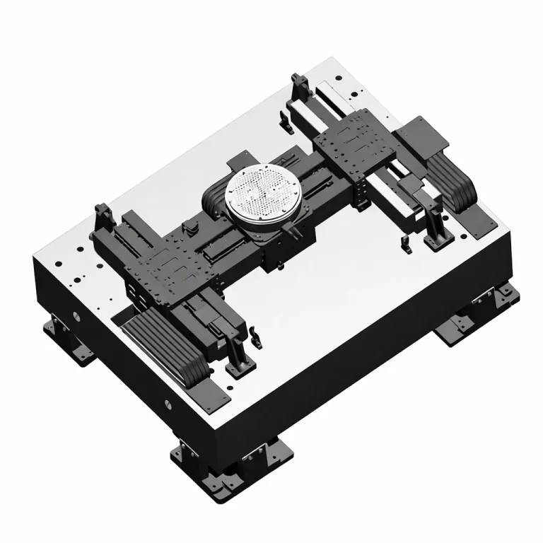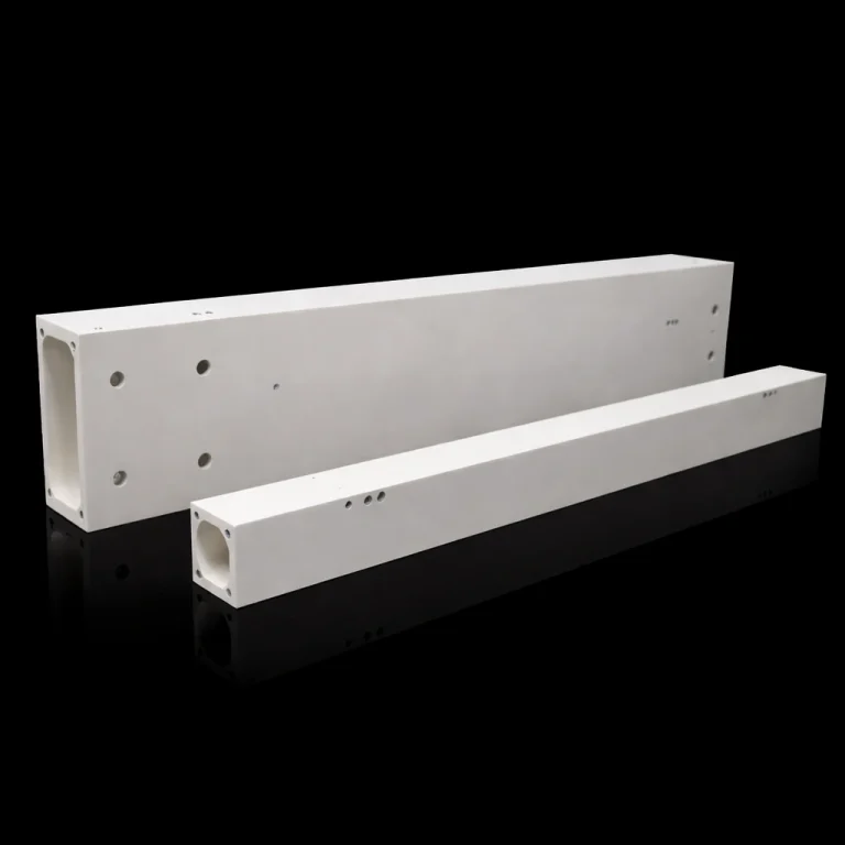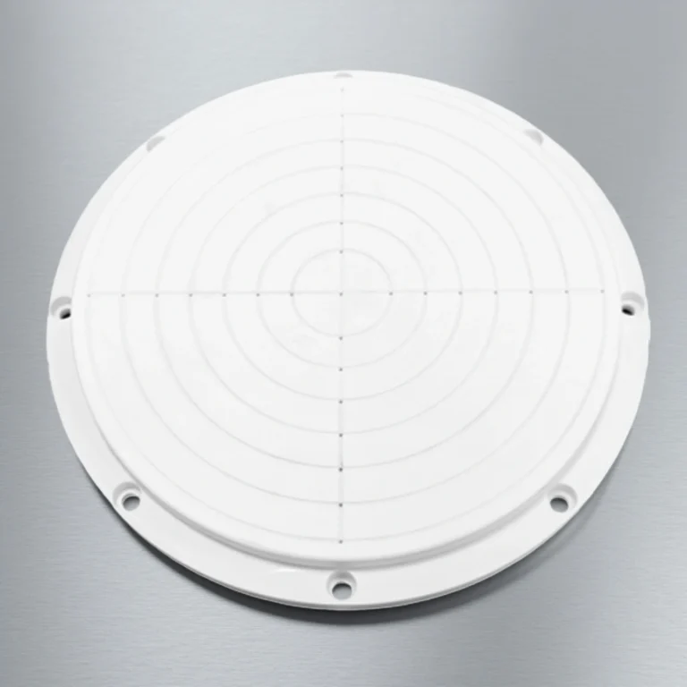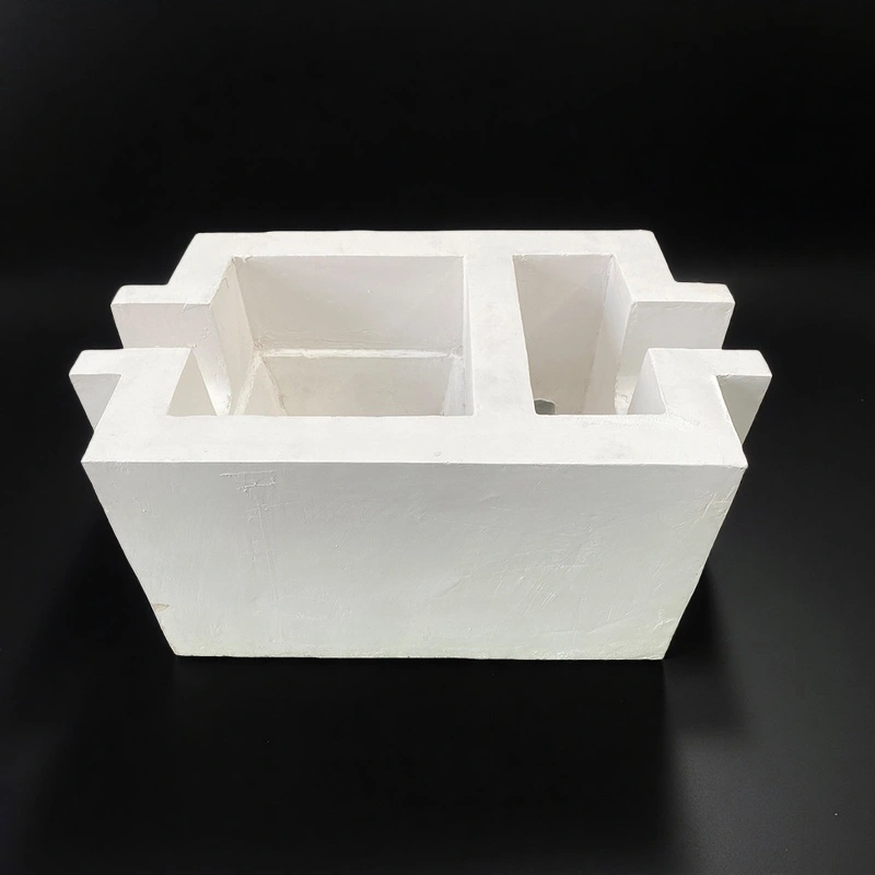

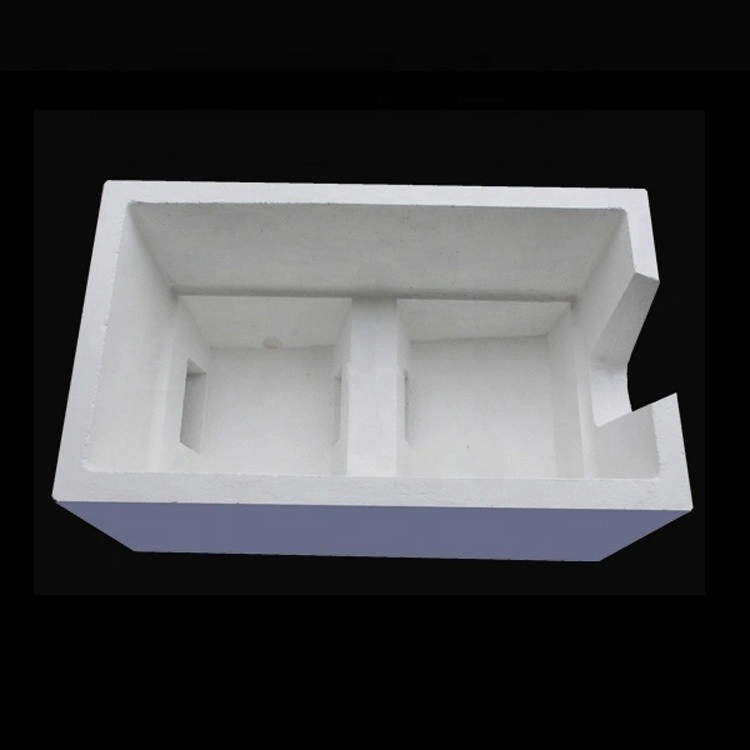
The aluminum silicate filter box is a prefabricated molten aluminium filtration vessel made from aluminum silicate ceramic fiber and inorganic refractory materials, matched with a steel shell when required. It is designed to house a ceramic foam filter plate and create a stable filter chamber for molten aluminum and aluminum alloy streams in extrusion billet, slab casting and foundry lines.
Aluminum Silicate Filter Box Benefits
-
Stable Filter Cavity Geometry
The aluminum silicate filter box provides a rigid, dimensionally stable cavity for the ceramic foam filter plate, helping maintain consistent metal head and flow distribution across the filter surface. -
High Thermal Shock and Mechanical Resistance
The aluminum silicate ceramic fiber lining withstands rapid temperature changes and metal impact when filling, reducing cracking and spalling compared with traditional dense bricks or castables in many casthouse applications. -
Low Thermal Conductivity, Improved Temperature Control
The low thermal conductivity of aluminum silicate ceramic fiber minimizes heat loss through the filter box wall, helping keep molten aluminium close to casting temperature and reducing energy demand in the launder system. -
Non-Stick Aluminium Working Surface
Properly designed aluminum silicate filter boxes exhibit non-wetting behavior toward molten aluminium, reducing buildup on the working surface and limiting refractory inclusions detaching into the metal stream. -
Integration with Fibre Launders and Degassing Systems
Aluminum silicate filter boxes can be combined with aluminum silicate launders and degassing boxes to form a complete molten aluminum filtration and treatment line, providing a compact and consistent flow path from furnace to mould.
Aluminium Silicate Filter Box Properties
| Aluminum Silicate Ceramic | ||
| Parameter | Typical Value | Notes / Industrial Relevance |
| Material Composition | Al₂O₃–SiO₂ | Silicate-based refractory matrix |
| Working Temperature | 1000–1400°C | Depends on density & grade |
| Bulk Density | 200–400 kg/m³ | Lower density = better insulation |
| Thermal Conductivity | 0.08–0.22 W/m·K | Measured at 600–1000°C |
| Linear Shrinkage | ≤ 2% at 1000–1300°C | Ensures dimensional stability |
| Cold Crushing Strength | 0.6–1.2 MPa | Resistance to mechanical load |
| Thermal Shock Resistance | High | Suitable for rapid heating cycles |
| Water Absorption | Low | Supports clean installation |
| Available Thickness | 10–75 mm | Custom thickness on request |
| Available Forms | Boards, blocks, custom-machined shapes | Supports OEM engineering designs |
Aluminium Silicate Filter Box Specification
| Item | Length(mm) | Width(mm) |
| AT-GSL-GL1001 | 178 | 178 |
| AT-GSL-GL1002 | 230 | 230 |
| AT-GSL-GL1003 | 305 | 305 |
| AT-GSL-GL1004 | 381 | 381 |
| AT-GSL-GL1005 | 432 | 432 |
| AT-GSL-GL1006 | 508 | 508 |
| AT-GSL-GL1007 | 584 | 584 |
| AT-GSL-GL1008 | 635 | 635 |
| AT-GSL-GL1009 | 660 | 660 |
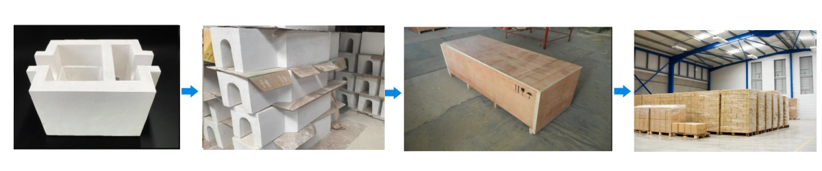
Aluminum Silicate Ceramic Filter Box Packaging
- Each aluminum silicate filter box is typically packed in a reinforced wooden crate with internal supports at non-working surfaces to avoid damage to the ceramic fiber liner.