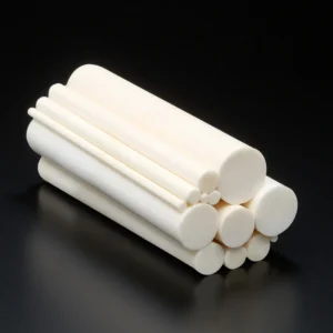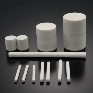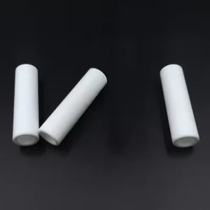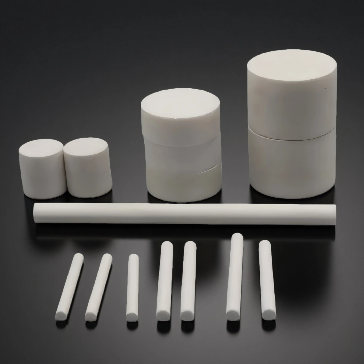
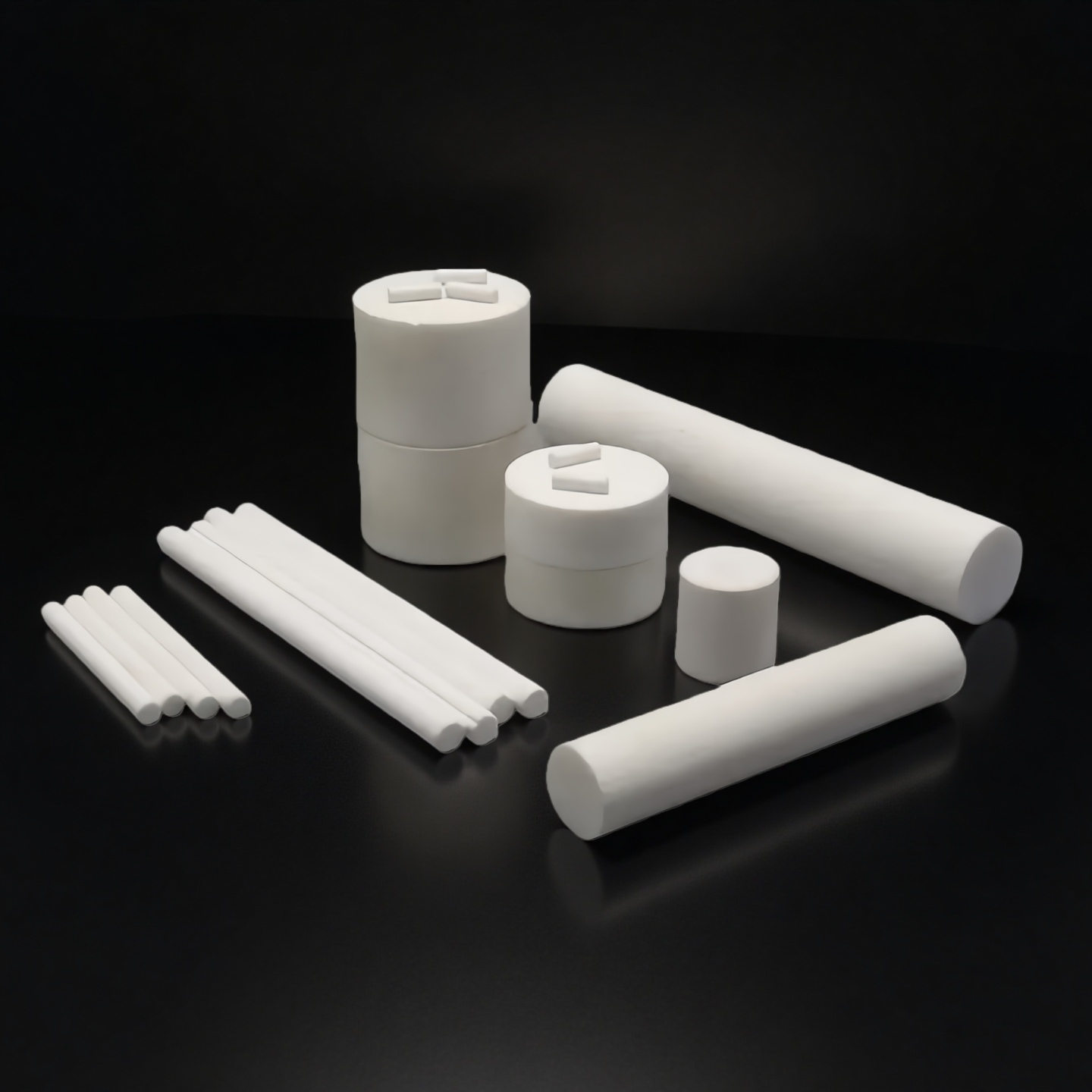
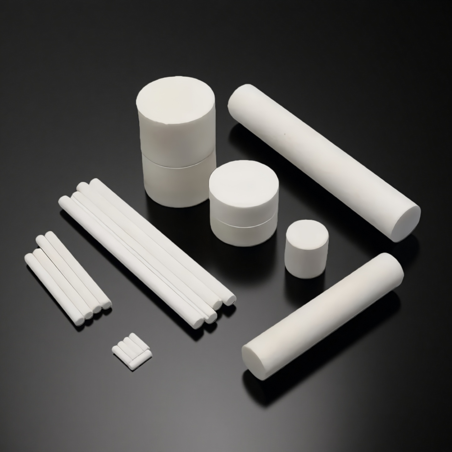
Machinable glass ceramic rod is used when an insulating round component must be machined quickly into standoffs, spacers, support posts, heater holders or fixture pins. Compared with many fully sintered ceramic rods, this material allows easier turning, drilling and milling before final assembly, making it suitable for vacuum equipment, high-voltage structures, RF fixtures, laboratory systems and prototype ceramic components.
Key Advantages of Machinable Glass Ceramic Rod
Faster Machining for Prototype and Low-Volume Components
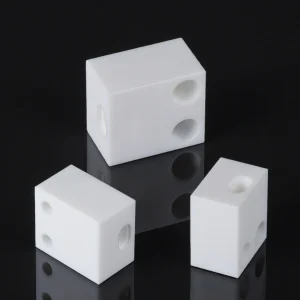
Machinable glass ceramic rods can be turned, drilled, milled and cut with suitable carbide tools. This helps engineers shorten prototype cycles when a design needs holes, flats, grooves, chamfers or stepped features before final assembly.
Electrical Insulation for Compact Assemblies
The material provides high electrical insulation for standoffs, spacers and support rods used in high-voltage, RF and heater-related structures. This helps reduce unwanted conductive paths when metal parts cannot be used near electrodes, leads or energized components.
Better Heat Stability Than Polymer Insulators
Compared with many polymer or plastic insulating rods, machinable glass ceramic rods maintain shape and insulation performance at much higher temperatures. This makes them useful in compact systems where insulation, heat and dimensional stability must be considered together.
Useful Alternative When Alumina Is Too Slow to Machine
Alumina ceramic rods remain suitable for higher-temperature or higher-wear applications, but they usually require diamond grinding after sintering. Machinable glass ceramic rods are often selected when the application temperature is lower and the design requires faster machining or easier modification.
Rod Stock and Machined Part Supply in One Route
ADCERAX can support both standard rod stock supply and drawing-based machined rod components. This helps customers decide whether to machine the rod in-house or purchase finished ceramic components with controlled dimensions and protected surfaces.
Machinable Glass Ceramic Rod Properties
| Machinable Glass Ceramic Physical Properties | ||
| Property | Typical value | Notes |
| Purity | ≥ 99.9 % | Some grades can reach 99.99 % |
| Density | 2.5–2.6 g/cm³ | Archimedes method |
| Open porosity | ≤ 0.07 % | Effectively non-porous |
| Water absorption | 0 % | No measurable uptake |
| Colour | White | Clean, uniform appearance |
| Hardness (Mohs) | 4–5 (up to 6–7) | Depending on grade |
| Machinable Glass Ceramic Thermal Properties | ||
| Property | Typical value | Notes |
| Coefficient of thermal expansion (CTE) | 72 × 10⁻⁷ /°C | Average from −50 to 200 °C |
| CTE 25–300 °C | 90 × 10⁻⁷ /°C | For design over mid-range temperatures |
| CTE 25–600 °C | 112 × 10⁻⁷ /°C | |
| CTE 25–800 °C | 123 × 10⁻⁷ /°C | |
| Thermal conductivity | 1.7 W/m·K | At 25 °C |
| Continuous use temperature | ~800 °C | Long-term service |
| Short-term maximum temperature | ~1000 °C | Depends on load and atmosphere |
| Machinable Glass Ceramic Mechanical Properties | ||
| Property | Typical value | Notes |
| Young’s modulus | ≈ 65 GPa | Room temperature |
| Flexural strength | ≥ 100 MPa | Three-point bending |
| Compressive strength | ≥ 500 MPa | Room temperature |
| Impact resistance | ≥ 2.56 kJ/m² | Indicative value for brittle fracture |
| Poisson’s ratio | ≈ 0.29 | |
| Shear modulus | ≈ 25 GPa | Derived from E and ν |
| Machinable Glass Ceramic Electrical Properties | ||
| Property | Typical value | Notes |
| Dielectric constant (1 kHz) | 6–7 | 25 °C |
| Dielectric loss (tan δ, 1 kHz) | 1–4 × 10⁻³ | 25 °C |
| Dielectric strength | > 40 kV/mm | Sample thickness 1 mm |
| Volume resistivity @ 25 °C | ≈ 1.0 × 10¹⁶ Ω·cm | High insulation level |
| Volume resistivity @ 200 °C | ≈ 1.5 × 10¹² Ω·cm | |
| Volume resistivity @ 500 °C | ≈ 1.1 × 10⁹ Ω·cm | |
Machinable Glass Ceramic Bar Specifications
| Machinable Glass Ceramic Rod | ||
| Item | Diameter (mm) | Width (mm) |
| AT-KJG-TC2001 | 0.5 | 60 |
| AT-KJG-TC2002 | 1 | 100 |
| AT-KJG-TC2003 | 2 | 120 |
| AT-KJG-TC2004 | 5 | 200 |
| AT-KJG-TC2005 | 10 | 100 |
| AT-KJG-TC2006 | 15 | 100 |
| AT-KJG-TC2007 | 20 | 100 |
| AT-KJG-TC2008 | 25 | 100 |
| AT-KJG-TC2009 | 30 | 100 |
| AT-KJG-TC2010 | 35 | 100 |
| AT-KJG-TC2011 | 40 | 100 |
| AT-KJG-TC2012 | 45 | 100 |
| AT-KJG-TC2013 | 50 | 100 |
| AT-KJG-TC2014 | 55 | 100 |
| AT-KJG-TC2015 | 60 | 100 |
| AT-KJG-TC2016 | 65 | 100 |
| AT-KJG-TC2017 | 70 | 100 |
| AT-KJG-TC2018 | 75 | 100 |
| AT-KJG-TC2019 | 80 | 100 |
| AT-KJG-TC2020 | 85 | 100 |
| AT-KJG-TC2021 | 90 | 100 |
| AT-KJG-TC2022 | 95 | 100 |
| AT-KJG-TC2023 | 100 | 100 |
| AT-KJG-TC2024 | 105 | 100 |
| AT-KJG-TC2025 | 110 | 100 |
| AT-KJG-TC2026 | 115 | 100 |
| AT-KJG-TC2027 | 120 | 100 |
| AT-KJG-TC2028 | 0.5-200 (Custom) | 10-300 (Custom) |
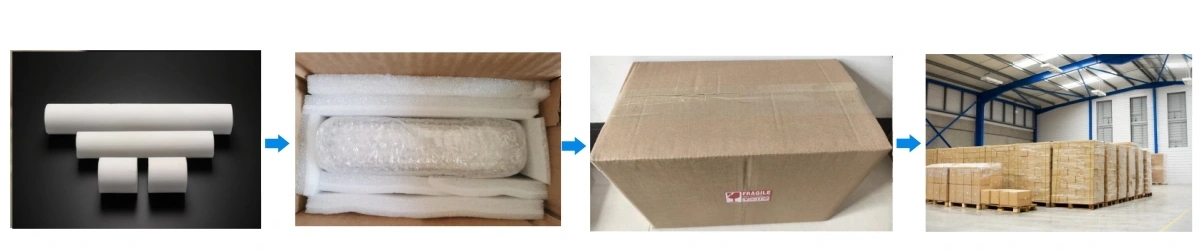
Machinable Glass Ceramic Bar Packaging
- Machinable glass ceramic rods are packed to reduce end chipping, surface scratches, contamination and mixed-size handling errors during international shipment. Each rod can be individually wrapped with soft film, foam sleeve or protective paper, with additional end protection for cut or machined surfaces.
- For machined rods with holes, chamfers, fine surfaces or critical contact areas, ADCERAX® can separate parts by size or drawing number and use padded inner boxes before placing them into an outer carton or wooden case. Labels, part numbers and quantity information should be kept clear to support incoming inspection and warehouse handling.