Why Choose ADCERAX for Custom Ceramic Parts?
ADCERAX operates primarily as a custom ceramic manufacturer, with 85% of production dedicated to engineered components. Our equipment and workflow are built to handle small-batch precision work—not mass production of catalog parts.
85%
Projects Are Custom Orders
Customization Defines Practical Reliability
Standard ceramic parts are built to satisfy broad use cases, not the realities of specific assemblies. Customization becomes necessary when real interfaces, real loads, and real environments begin to dominate performance.
Standard ceramic parts often appear suitable at first glance.
Once they are placed into real assemblies, their limitations tend to surface quickly.
Designed for averages, not actual system behavior
Ceramics cannot be corrected after installation
Small mismatches often lead to early failure
Customization Triggers in Real Projects
Most projects arrive at customization because something no longer works as expected. The need rarely comes from ambition, but from practical constraints inside existing systems.

Standard parts clash with housings, mounts, or fixtures

Cracks or wear appear once real operating conditions combine

Older systems leave little room for substitution

Small batches must balance reliability with delivery speed
Engineering-First Custom Ceramic Services
Custom Services for Ceramic Parts work best when engineering judgment leads decisions rather than drawings alone. Real operating conditions, assembly context, and failure history shape outcomes far more than geometry on paper.

Operating Condition Anchoring
Temperature, load, and media define success more than shape
Thermal mismatch and stress paths surface before production
Durability expectations guide material and structure choices

Failure-Mode-Driven Design
Geometry choices reduce chipping and thermal shock risks
Contact areas receive attention where damage actually starts
Interfaces are shaped to seal reliably, not just look precise

Interface-Focused Customization
Engineering effort concentrates where performance truly depends
Non-critical zones remain manufacturable and cost-controlled
Ceramics are shaped to work with metals, not fight them

Production-Ready Engineering Logic
Repeatable routes replace one-time success
Dimensional consistency improves across batches
Quality checks follow function, not formality
Customization Beyond Standard Ceramic Parts
Custom Services for Ceramic Parts go deeper than dimensions, focusing on parameters that decide real-world performance.

Material System Selection
Materials are chosen for risk, not labels
Expansion and heat flow match system demands
Media exposure guides long-term stability

Purity and Microstructure
Stability comes from what happens inside the material
Small inclusions often cause large failures
Uniform behavior matters more than peak values

Tolerance Strategy
Tight tolerances appear only where assemblies depend on them
Ceramic forming limits are respected early
Tolerances reflect how different materials move together

Surface Engineering
Smoothness applied only where contact requires it
Avoiding unnecessary polishing shortens lead time
Finish decisions follow function, not appearance
Achievable Precision Tolerances for Custom Ceramic Components
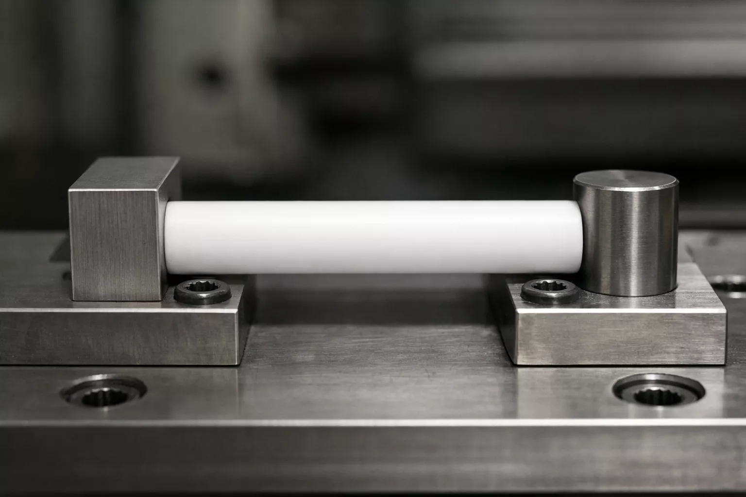
Tolerance capability determines whether custom ceramic parts perform reliably in assemblies with metal housings, seals, or tight clearances. ADCERAX's grinding and inspection systems achieve the following precision levels on critical dimensions:
Diameter Precision
±0.01mm
Outer diameter, inner diameter on tubes and rods
Hole Depth Precision
Minimum Wall Thickness
Surface Roughness
Cylindricity
±0.004mm
Straightness control on tubes and rods
Concentricity
±0.003mm
Inner/outer diameter alignment on tubes
Internal Thread
M2 and larger
Ceramic tapped holes for mechanical assemblies
Flatness
±0.002mm
Plate surfaces, mounting faces, sealing surfaces
💡 Material Selection Guidance: Material selection depends on operating temperature, chemical exposure, thermal shock resistance, and mechanical load. Engineering teams can recommend the optimal grade based on your application conditions.
Common applications requiring these precision levels:
Semiconductor equipment seal faces (±0.01mm flatness), vacuum furnace thermocouple protection tubes (±0.01mm OD for housing fit), analytical instrument sampling probes (±0.005mm concentricity), high-pressure pump plungers (Ra 0.5μm surface finish).
Size Range and Material Capabilities
Material Options for Custom Work
- Alumina (Al₂O₃): 95%, 99%, 99.5%, 99.7%, 99.9% purity grades
- Zirconia (ZrO₂): Yttria-stabilized (3Y-TZP), Magnesia-stabilized (MSZ)
- Silicon Carbide (SiC): Sintered SiC, Reaction-bonded SiC, Nitride-bonded SiC
- Silicon Nitride (Si₃N₄): Hot-pressed and sintered grades
- Boron Nitride (BN): Hot-pressed and machinable grades
- Zirconia-Toughened Alumina (ZTA): 10-20% ZrO₂ dispersion
- Aluminum Nitride (AlN): High thermal conductivity substrates
Dimensional Capabilities
| Feature Type | Minimum Size | Maximum Size | Typical Applications |
|---|---|---|---|
| Tube Outer Diameter | 2mm | 300mm | Micro sampling probes to large furnace liners |
| Tube Length | 10mm | 3000mm | Short bushings to continuous process tubes |
| Wall Thickness | 0.2mm | 50mm | Thin-walled insulators to thick crucible walls |
| Hole Diameter (drilled) | 0.5mm | 200mm | Gas injection holes to large bore tubes |
| Internal Thread | M2 | M100 | Mounting screws to large threaded fittings |
💡 Material Selection Guidance: Material selection depends on operating temperature, chemical exposure, thermal shock resistance, and mechanical load. Engineering teams can recommend the optimal grade based on your application conditions.
The Right Time to Involve Engineering
Projects benefit most when engineering joins before decisions harden.
Early involvement prevents small uncertainties from becoming expensive corrections later.
Minor changes avoid major rework
Teams agree on what truly matters
Fewer surprises shorten validation
Custom Ceramic Parts: Frequently Asked Questions
Technical answers to help you specify, source, and use alumina ceramics substrate effectively.
Custom Ceramic Component Case Examples
These examples reflect actual engineering challenges solved through custom ceramic design and manufacturing. Details have been generalized to protect customer confidentiality, but technical requirements and outcomes are accurate.
What is the minimum order quantity for custom ceramic parts?
As few as 3 pieces for simple dimensional modifications (length adjustments, diameter changes within existing tooling capabilities).
For completely new geometries requiring new tooling (molds, fixtures), the practical minimum is typically 10-50 pieces depending on part complexity and material. This accounts for the setup, trial runs, and inspection required to validate new ceramic forming processes.
Can you make 3-5 test pieces before a full production run?
Yes. Sample production is standard practice for custom ceramic parts, especially when tolerances are critical or the part will be installed in expensive equipment.
Typical sample process:
- Engineering review of drawing and requirements (1-2 days)
- Trial production of 3-5 sample pieces (3-14 days depending on material and geometry)
- Dimensional inspection report provided with samples
- Customer approval before proceeding to batch production
Sample costs are typically credited toward the final order if the project moves to production quantities (>50 pieces).
How long does custom ceramic part production take?
- Simple modifications (using existing tooling): 3-5 days
Examples: Cutting standard tubes to non-catalog lengths, drilling additional holes, grinding specific surface zones - New geometries (requiring new tooling or molds): 2-4 weeks
Includes tooling fabrication, trial runs, dimensional validation, and first article inspection - Complex multi-feature assemblies: 4-6 weeks
Parts with tight tolerances on multiple features, multi-step machining, or materials requiring specialized firing cycles
Rush service: Available for critical projects. Lead time can often be reduced by 30-50% with priority scheduling. Contact engineering to discuss feasibility.
How much do custom ceramic parts cost compared to standard catalog items?
Custom pricing depends on several factors: material grade, dimensional complexity, tolerance requirements, surface finish needs, and order quantity.
General guidelines:
- Simple modifications: Similar to catalog pricing for quantities >20 pieces. Small quantity premium (3-10 pieces) adds setup overhead.
- New tooling required: One-time tooling cost (amortized across order quantity) plus part cost. Tooling investment is typically recovered at 100-200 piece volumes.
- Precision grinding: Tight tolerance zones (±0.01mm or better) require additional grinding operations. Cost impact depends on number of critical features.
Most custom quotes are provided within 24-48 hours of receiving drawings and application details. No-obligation quotations include lead time estimates and any engineering recommendations.
Do you provide material certificates and inspection reports?
Yes. Material certifications and dimensional inspection reports are provided with all custom orders.
Standard documentation includes:
- Material Certificate: Chemical composition, purity grade, density, and key physical properties from powder supplier or in-house testing
- Dimensional Inspection Report: Measurement results for all specified tolerances, performed with calibrated CMM, calipers, or optical measurement systems
- Surface Quality Report: Roughness measurements (Ra/Rz) for critical surfaces when specified
Additional testing available on request: Hardness testing, leak testing (for sealed components), thermal shock testing, or third-party certification (SGS, TÜV, etc.).
All reports are provided in PDF format via email. Hard copies can be included with shipment if required for quality system documentation.
What information do you need to quote a custom ceramic part?
Minimum information for quotation:
- Drawing or sketch showing dimensions and tolerances (2D PDF, DWG, or 3D STEP file preferred)
- Material specification (e.g., “99.7% alumina” or “sintered silicon carbide”) or operating temperature if material is flexible
- Quantity required (even an approximate range helps determine tooling approach)
- Surface finish requirements if critical (as-fired, ground, polished, or specific Ra value)
Additional helpful information:
- Operating temperature and chemical environment
- Mating part materials (metal housing, rubber seal, etc.)
- Failure history if replacing an existing part
- Target delivery date if time-sensitive
Engineering teams can work from incomplete information and suggest options, but detailed specifications reduce revision cycles and accelerate delivery.
Can you work from my CAD files or do I need to provide 2D drawings?
Both 2D and 3D formats are accepted.
Preferred file formats:
- 3D CAD: STEP (.stp), IGES (.igs), Parasolid (.x_t)
- 2D drawings: PDF, DWG, DXF
- Sketches: Hand-drawn dimensions (photo or scan) for early-stage concept discussions
Engineering teams will review for ceramic manufacturability—features like sharp internal corners, undercuts, or extremely thin walls may require design adjustments. Recommendations are provided during the quotation stage, not after tooling is built.
What if the custom parts don’t meet the specified tolerances?
Quality guarantee: Parts that do not meet agreed-upon dimensional or material specifications are reproduced at no additional cost, or the order is refunded.
Process:
- Customer reports dimensional non-conformance with measurement data
- ADCERAX engineering reviews measurements and compares to inspection records
- If confirmed out-of-specification, replacement parts are prioritized and expedited
First article inspection (FAI) option: For critical applications, a single sample part can be produced, inspected, and shipped for customer verification before the full batch is manufactured. This eliminates risk on high-tolerance or high-value orders.

High-Precision Alumina Tube for Semiconductor Equipment Seal Assembly
Industry: Semiconductor Processing
Region: North America
Material: 99.7% Alumina
Challenge
- A semiconductor equipment manufacturer required a custom alumina protection tube for a high-vacuum chamber thermocouple assembly. The tube interfaces with a metal compression fitting that provides hermetic sealing at elevated temperatures.
- Outer diameter tolerance: ±0.01mm over 500mm length (compression seal fit)
- Concentricity between OD and ID: ±0.005mm (ensures thermocouple probe clearance)
- Surface roughness Ra <0.8μm on OD sealing zone (metal seal compatibility)
- No standard catalog tube met the length and OD precision combination
Solution
- Selected isostatic pressing method to achieve consistent wall thickness and concentricity along 500mm length
- Applied centerless grinding to OD sealing zone (80mm length) to reach ±0.01mm tolerance and Ra 0.6μm finish
- Implemented 100% dimensional inspection with coordinate measuring machine (CMM) to verify concentricity and diameter consistency
Outcome
Initial order of 20 tubes for equipment validation, followed by repeat orders totaling 150+ tubes over 18 months
12 days for first batch (including tooling setup), 8 days for repeat orders
Tubes passed customer’s 2000-hour thermal cycling test with zero seal failures. Customer reported elimination of previous leak issues caused by standard-tolerance tubes.
-
Engineering Insight:
Achieving ±0.01mm OD tolerance over 500mm length required post-sintering centerless grinding. Standard alumina tubes (±0.2mm tolerance) would have caused intermittent seal leaks due to OD variation exceeding compression fitting tolerance budget. The 10x tighter tolerance added approximately 30% to part cost but eliminated expensive equipment downtime and warranty claims.

Custom-Geometry Alumina Crucible for High-Temperature Materials Research
Industry: University Research Lab
Region: Europe
Material: 99.5% Alumina
Challenge
- A materials science research group needed custom alumina crucibles with integrated drain holes for molten metal casting experiments. Standard crucibles lack bottom drainage, requiring manual pouring that introduces oxidation and contamination risks.
- Cylindrical crucible: 80mm OD × 70mm ID × 100mm height
- Three 3mm diameter drain holes equally spaced around bottom center
- Drain holes must be clean (no burrs or microcracks that could propagate during thermal shock)
- Quantity: 15 crucibles for ongoing experimental program
Solution
- Crucibles formed using dry pressing method (standard process for thick-walled vessels)
- Drain holes introduced via laser drilling after sintering—laser method avoids mechanical stress and produces clean hole edges without microcracking
- Holes inspected under microscope to verify edge quality (no chips or radial cracks >0.05mm from hole perimeter)
Outcome
18 days from order to delivery (including laser drilling setup and inspection protocol development)
Research group reported successful drain functionality with no hole blockage or edge degradation after 50+ melt cycles at 1600°C
Customer placed two additional orders (12 and 20 crucibles) for expanded research program
-
Engineering Insight:
Small-diameter holes (3mm) in alumina are typically drilled mechanically, but this creates edge chipping risk and potential crack initiation sites under thermal shock. Laser drilling produces smoother hole edges and eliminates subsurface damage, which is critical for crucibles experiencing repeated thermal cycling. The laser drilling added approximately 15% to crucible cost but eliminated early failure risk.

Extended-Length Silicon Carbide Tube for Continuous Sintering Furnace
Industry: Advanced Ceramics Manufacturing
Region: Asia
Material: Reaction-Bonded Silicon Carbide (RBSC)
Challenge
- A ceramics manufacturer needed to replace failed silicon carbide muffle tubes in a continuous sintering furnace. Original tubes (2500mm length) were sourced from a supplier no longer in operation, and no direct replacement was available in standard catalogs.
- Tube dimensions: 2500mm length × 120mm OD × 110mm ID
- Material: Reaction-bonded SiC (RBSC) for thermal shock resistance and oxidation resistance at 1450°C operating temperature
- Straightness tolerance: <2mm total deviation over 2500mm length (to fit furnace support rails)
- Lead time: <4 weeks (furnace downtime cost was significant)
Solution
- Used reaction-bonded SiC process (RBSC) rather than sintered SiC—RBSC method allows longer tubes with better dimensional control and lower cost
- Tubes formed in two 1250mm segments with precision-machined joint faces, then joined using high-temperature ceramic adhesive designed for SiC
- Post-joining straightness measured and corrected via targeted grinding on support zones to achieve <2mm total deviation
Outcome
6 tubes delivered (4 installed immediately, 2 kept as spares)
26 days (met customer’s 4-week deadline despite segmented manufacturing approach)
Tubes installed and furnace returned to operation. Customer reported over 8 months of continuous operation with no tube failures or warping—matching performance of original equipment tubes.
-
Engineering Insight:
Silicon carbide tubes >2000mm length are challenging to produce as single monolithic pieces due to dimensional control and handling difficulties during firing. The segmented approach (joining two precision-machined halves) achieved the required straightness while reducing manufacturing risk and cost. Joint strength was verified through thermal shock testing (1450°C to 300°C water quench) before shipment. This approach is now our standard method for SiC tubes >2000mm length.
Talk With
ADCERAX Engineering Team
Many ceramic challenges become clearer through conversation rather than revision cycles.
Sharing how a part actually works inside your system often reveals workable paths forward.
Engineering teams at ADCERAX focus on turning real operating constraints into ceramic solutions that fit assemblies, timelines, and long-term performance expectations.

Share your operating conditions or drawings, and engineers can assess feasibility and customization direction.
