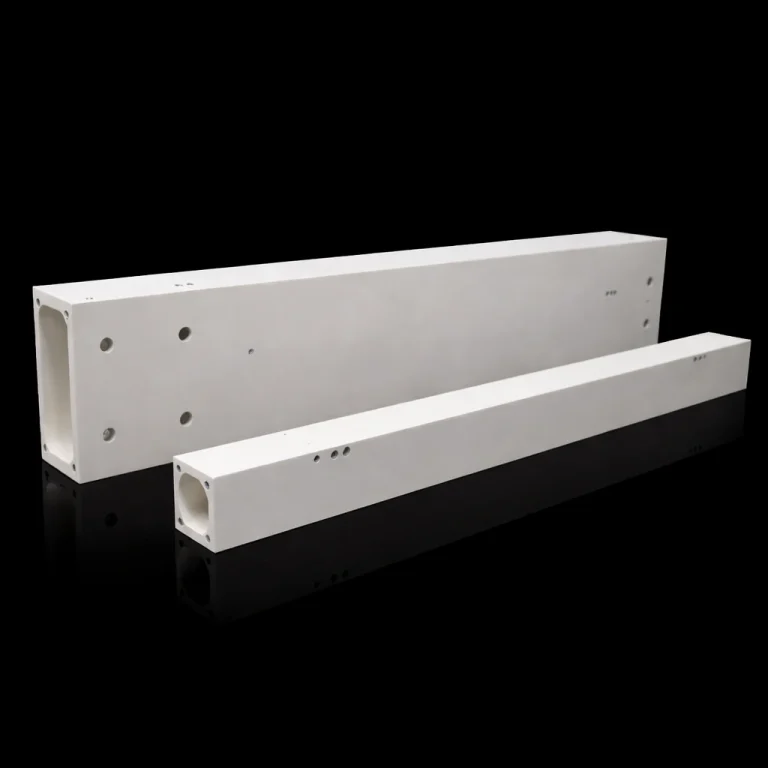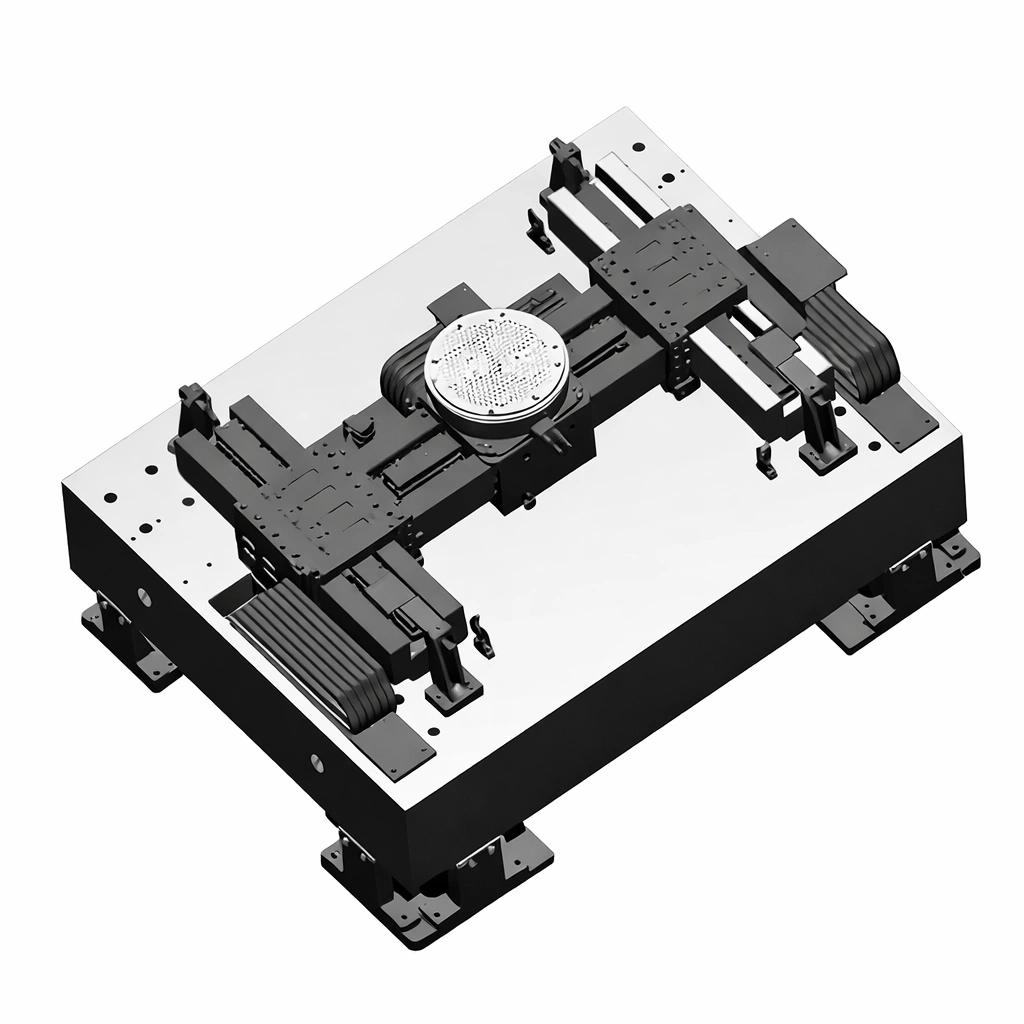
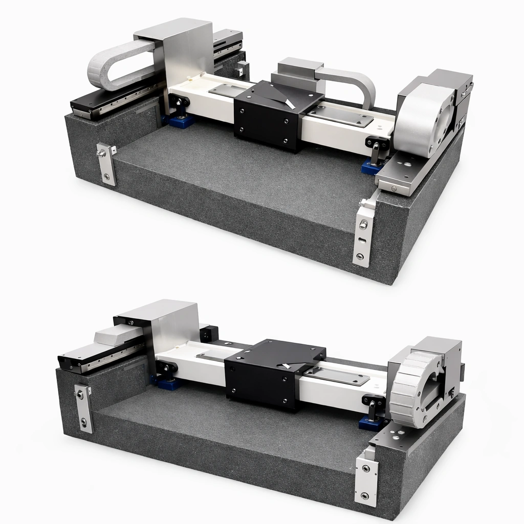
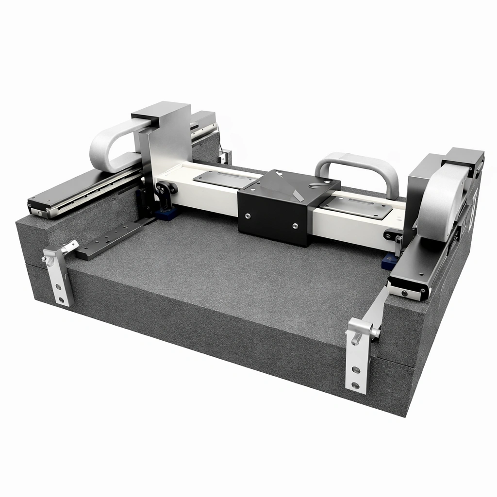
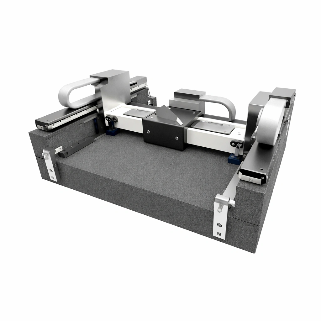
A Precision Air-Bearing Multi-Axis Motion Platform is a multi-axis positioning stage that floats on a thin pressurised air film, creating near-zero friction, non-contact motion. This structure eliminates stick-slip and mechanical wear so that the platform can maintain stable positioning performance with sub-micron repeatability during scanning, alignment, or pick-and-place routines. It is commonly integrated into metrology systems, optical inspection tools, laser processing equipment, and other precision automation machines where vibration control and motion smoothness directly affect yield and measurement uncertainty.
Precision Air-Bearing Multi-Axis Motion Platform Benefits
-
Ultra-Low Friction Air Bearings
Non-contact air film eliminates stick-slip and mechanical wear, keeping motion smooth across long duty cycles.
Ideal for scanning, alignment, and precision positioning where motion ripple and micro-vibration affect results. -
Customizable Dimensions & Axis Layouts
Platform length, stroke, axis stack (XY / XYZ / XYθ / XYZθ), and stage envelope can be defined to match your machine bay and tooling.
Cross-sections, datum faces, and mounting patterns can be built around your fixture strategy and metrology references. -
High Stability, Stiffness & Payload Control
Designed to maintain positioning stability under off-centre loads and changing payload conditions during acceleration and deceleration.
Supports stable multi-axis motion for heavy optics, fixtures, probes, or automation end-effectors with predictable deflection behaviour. -
Cleanroom & Contamination-Sensitive Compatibility
No rolling elements and no lubrication on the bearing interface reduce particle generation compared with mechanical guides.
Suitable for inspection, optical alignment, and precision measurement environments that require clean operation and repeatable performance. -
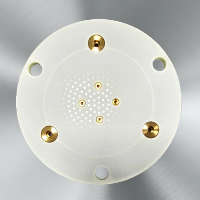
System-Level Integration Ready
Supports integration with direct-drive actuation (e.g., linear motor), feedback options (linear encoder), and air supply manifolds.
Common engineering options include cable routing zones, sensor mounting bosses, hard stops, and reference features for fast commissioning.
Precision Air-Bearing Multi-Axis Motion Platform Properties
| Property | Unit | 99.5% Al₂O₃ | 99.7% Al₂O₃ | 99.9% Al₂O₃ | 99.9% Al₂O₃ (Ivory) |
|---|---|---|---|---|---|
| Alumina content | % | 99.5 | 99.7 | 99.9 | 99.9 |
| Density | g/cm³ | 3.58 | 3.61 | 3.69 | 3.61 |
| Color | - | Ivory | Ivory | Ivory | Ivory |
| Water absorption | % | 0.03 | 0.02 | 0.01 | 0.02 |
| Young's modulus | GPa | 275 | 278 | 300 | 275 |
| Shear modulus | GPa | 105 | 109 | 116 | 105 |
| Bulk modulus | GPa | 362 | 365 | 385 | 362 |
| Compressive strength | MPa | 300 | 320 | 340 | 300 |
| Flexural strength | MPa | 305 | 310 | 320 | 305 |
| Fracture toughness | MPa·m½ | 3.5 | 3.6 | 3.8 | 3.5 |
| Thermal hardness | W/m·K | 14 | 14 | 14 | 14 |
| Thermal shock resistance ΔT | °C | 450 | 460 | 480 | 450 |
| Maximum use temperature (to load) | °C | 1200 | 1250 | 1300 | 1200 |
| Coefficient of thermal expansion | 10⁻⁶/°C | 7.5 | 7.4 | 7.3 | 7.5 |
| Hardness | - | 9.0 | 9.0 | 9.0 | 9.0 |
| Dielectric constant | - | 9.5 | 9.6 | 9.6 | 9.5 |
| Dissipation factor (loss factor) | (1 kHz) | 0.02 | 0.02 | 0.015 | 0.02 |
Precision Air-Bearing Multi-Axis Motion Platform Specifications
| Model No. | Dimensions (W×H×L) mm | Flatness (μm) | Parallelism (μm) |
|
|---|---|---|---|---|
| AT-JYI001 | 600x | 2 | ||
| AT-JYI002 | 800x | |||
| AT-JYI001 | 1200x | |||
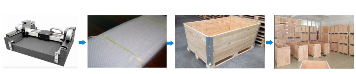
Precision Air-Bearing Multi-Axis Motion Platform Packaging
- Individually wrapped with anti-scratch film
- Foam-supported rigid export carton
- Optional wooden crate for long straightedge