Alumina Ceramic Lining Tube for Abrasion-Resistant Pipe Spools and Wear Zones

An alumina ceramic lining tube is a wear liner installed inside pipe spools for abrasive powder, ash, mineral or slurry service, supplied by ADCERAX as custom tubes by drawing with configurable inner/outer diameter, wall thickness and end features to match existing lines.

Catalog No. AT-YHL-NC01
Material ≥ 96% Al2O3
Maximum Temperature Up to 1650°C
Dimensional Tolerance ±0.2mm
Vickers Hardness ~16–17.2 GPa
24H Standard Dispatch
Small Batch Support OEM
Factory Direct
Expert Engineering Support

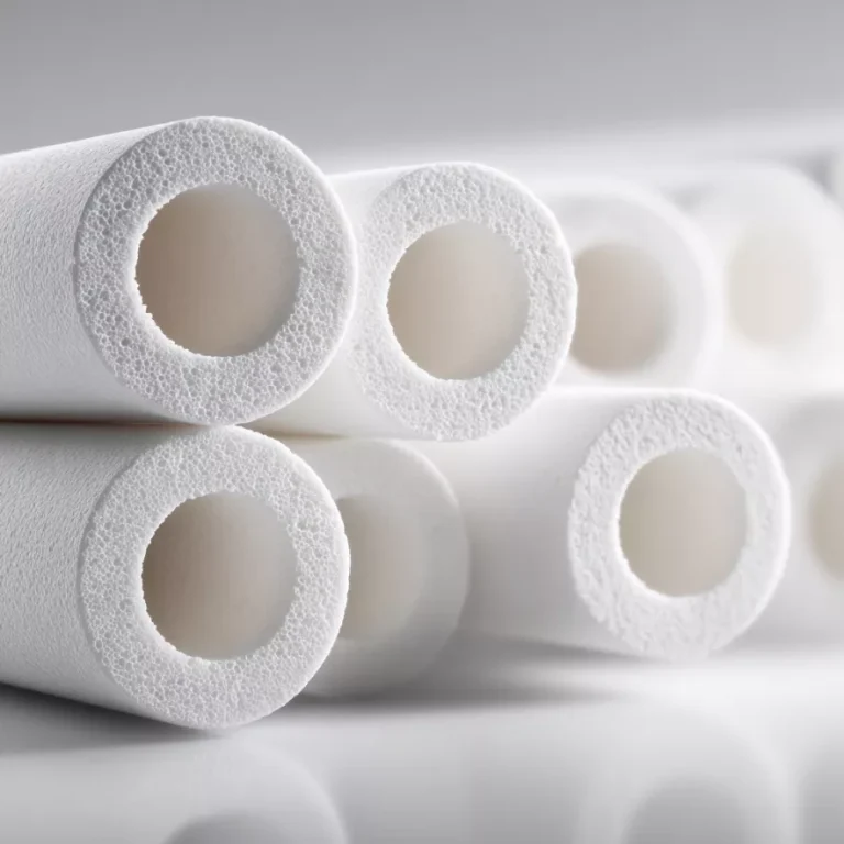
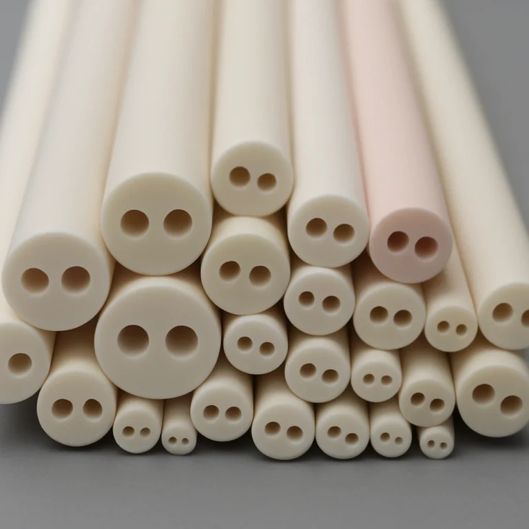
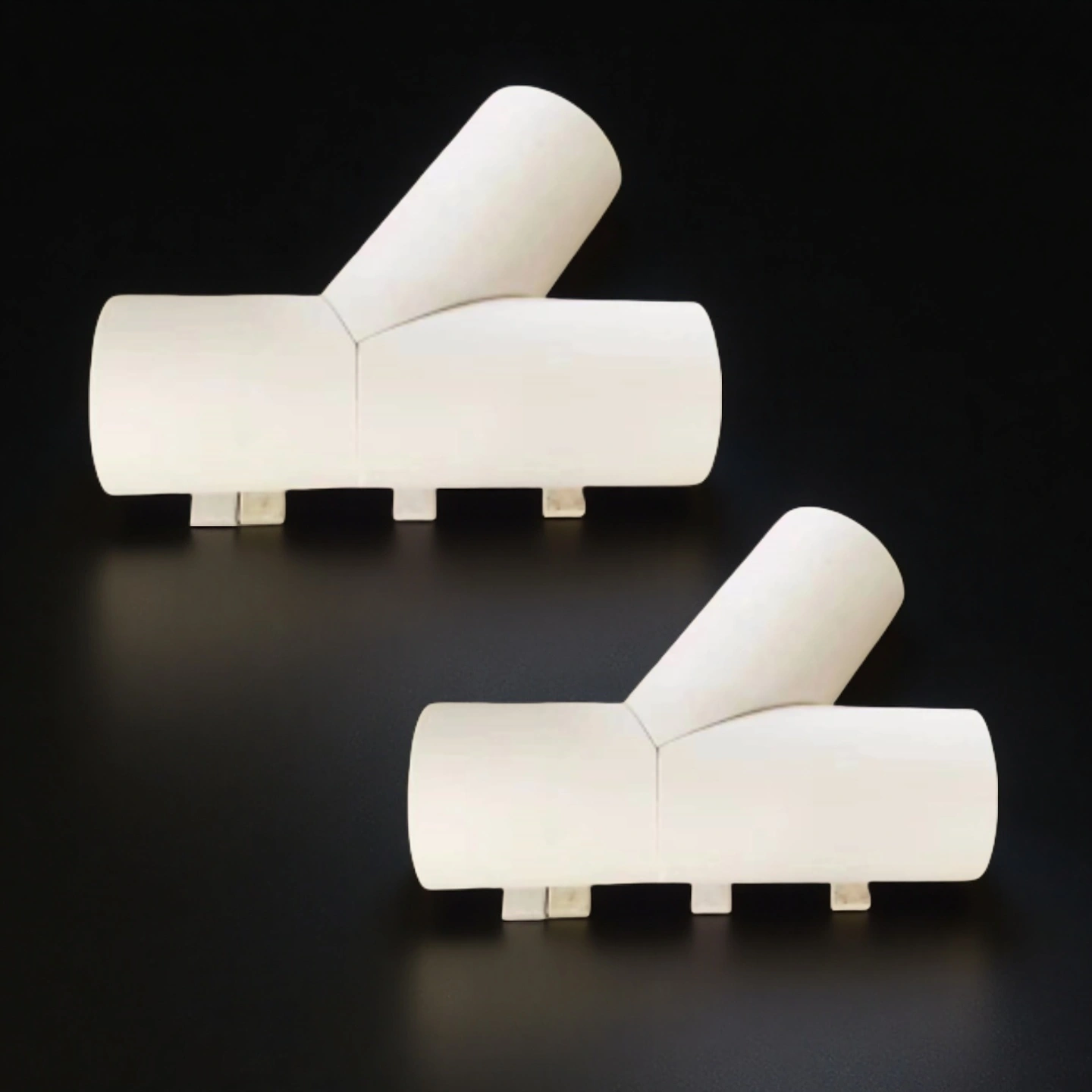
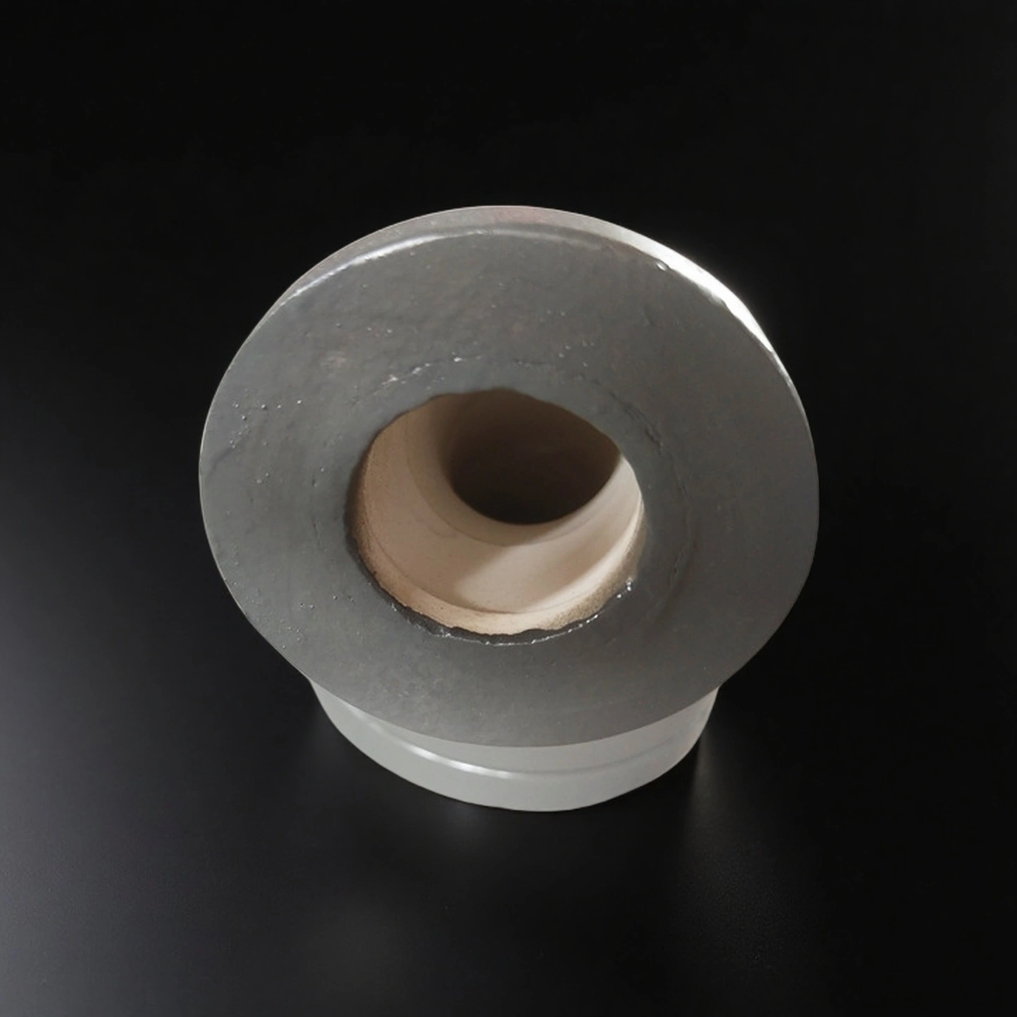
An alumina lining tube is a cylindrical wear liner made from high-alumina technical ceramic and installed inside a steel pipe or used as a standalone ceramic tube to protect flow passages that handle abrasive or chemically aggressive media. In bulk solids, ash, slurry and powder conveying systems, the alumina lining tube forms the actual flow surface

Alumina Lining Tube Advantages

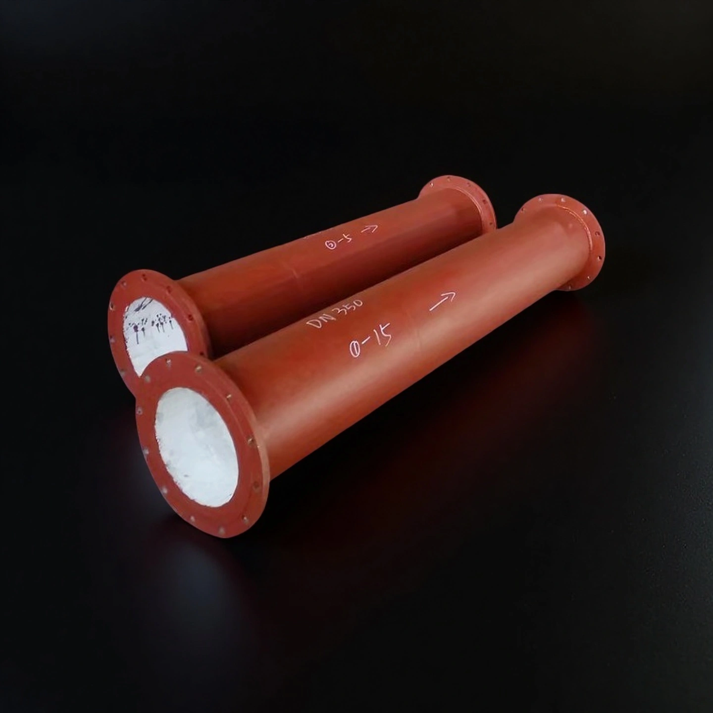
  • Predictable wear interface in straight spools: A stable liner bore keeps erosion concentrated on the ceramic surface instead of thinning the steel wall at random locations, which makes inspection points and maintenance intervals easier to plan. By keeping the internal diameter consistent along the length, the alumina ceramic lining tube also helps to maintain conveying velocity and pressure drop within the design window over a longer period.

  • Service-interval leverage in abrasive transport: In many abrasive conveying lines, public supplier application notes report multi-times wear life (often in the 5–10× range) for ceramic-lined sections compared with unlined steel under similar operating conditions. That extended life, even if derated for conservative design, allows maintenance managers to convert unplanned leak repairs into scheduled changeouts and to align liner replacement with existing shutdown windows.

  • Bondline-aware designs: For bonded constructions, the lining system can be specified around adhesive data that commonly lists a practical continuous-use window of roughly 100–240°C, depending on formulation and joint design. Above that range, or where temperature cycling and thermal gradients are expected, the alumina ceramic lining tube can be designed as a monolithic or mechanically retained liner so that performance is governed by the ceramic body rather than by the adhesive layer.

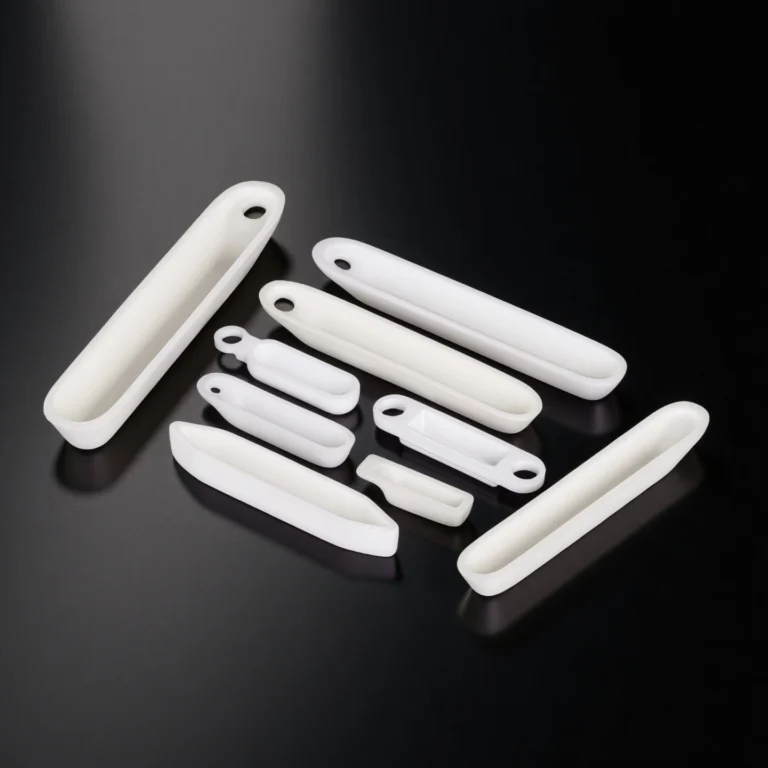
  • Maintenance-friendly segmentation options: Instead of replacing an entire pipe spool, replaceable liner sections allow maintenance teams to target only the zones that actually reach the wear limit, which reduces material usage and on-site work during a shutdown. Segmentation also makes it easier to keep spare parts on the shelf, since short standardized liner modules can be swapped into several locations without redesigning the whole assembly.

  • End-feature control: Chamfers, lead-ins, and carefully specified transition details at each end of the alumina ceramic lining tube reduce internal steps and sharp changes in cross-section that typically trigger localized erosion. By coordinating these features with the mating steel spool and gasket or coupling geometry, the design minimizes turbulence and particle impact at the joints, which are usually the first points to fail in high-velocity powder or slurry service.

Alumina Ceramic Lining Tube Properties

Property Unit 99.5% Al₂O₃ 99.6% Al₂O₃ 99.7% Al₂O₃ 99.8% Al₂O₃ 99.9% Al₂O₃ 99.99% Al₂O₃
Alumina content % 99.5 99.6 99.7 99.8 99.9 99.99
Density g/cm³ 3.89 3.91 3.92 3.93 3.94 3.98
Open porosity % 0
Color Ivory Ivory Ivory Ivory Ivory Ivory
Water absorption % 0 0 0 0 0
Young’s modulus (Elastic modulus) GPa 375 356 357 358 359 362
Shear modulus GPa 152
Bulk modulus GPa 228
Poisson’s ratio 0.22
Compressive strength MPa 2600 2552 2554 2556 2558 2570
Flexural strength MPa 379 312 313 314 315 320
Fracture toughness MPa·m¹ᐟ² 4
Hardness GPa 14.1 (≈1440 kg/mm²) 23 24 25 26 30
Thermal conductivity W/m·K 35 32–37 33–38 34–39 35–40 36–42
Thermal shock resistance ΔT °C 222 223 224 225 228
Maximum use temperature (no load) °C ≤1750 1755 1760 1765 1770 1800
Coefficient of thermal expansion 10⁻⁶/°C 8.4
Specific heat J/kg·K 880
Volume resistivity Ω·cm >1×10¹⁴ >1×10¹⁴ >1×10¹⁴ >1×10¹⁴ >1×10¹⁴ >1×10¹⁴
Dielectric constant (relative permittivity) 9.8 9.83 9.84 9.85 9.86 9.92
Dielectric strength kV/mm 16.9 23.2 23.4 23.6 23.8 24
Dissipation factor (loss factor @ 1 kHz) 0.0002


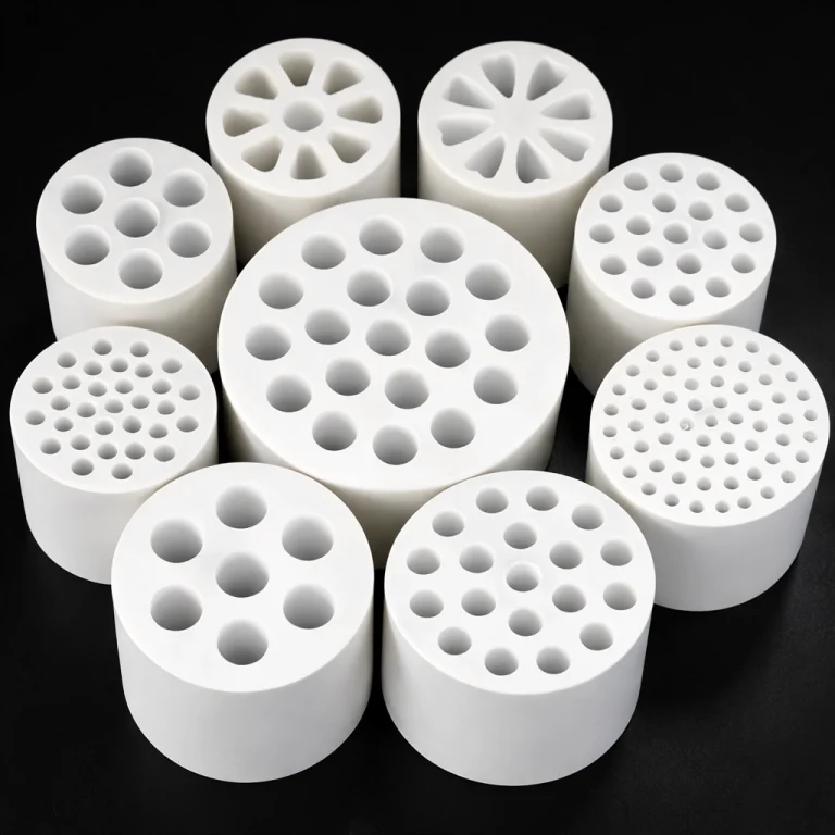
Alumina Ceramic Lining Tube Specifications

Alumina Ceramic Lining Tube
Item No. Diameter (mm) Thickness (mm)
AT-YHL-NC01 Customize


Alumina Lining Tube Packaging

  • Individual part protection: foam supports or molded inserts to prevent point-load cracking during transport.

Alumina Lining Tube Packaging

Alumina Ceramic Lining Tube Applications

  • Cement Plant Pneumatic Conveying (Powder, Clinker Dust, Raw Meal)

    ✅Key Advantages

    1. Wear-life leverage: supplier technical notes commonly claim 5–10× wear-life vs ordinary steel in abrasive conveying.

    2. Downtime-risk logic: public reliability surveys report unplanned downtime costs around US$125,000 per hour in many industrial settings.

    3. Temperature-fit selection: adhesive-lined systems are often published around ~100–240°C limits, supporting integral liners when temperatures exceed that boundary.

    ✅ Problem Solved

    A cement plant repeatedly replaces a high-wear spool section on a compressed-air conveying line due to rapid wall loss and unplanned stoppages. Using public wear-life claims (5–10× vs steel) as a screening benchmark, the plant targets longer service intervals to reduce emergency changeouts. The procurement team models downtime exposure using public estimates such as US$125,000/hour, where even an 8-hour event can be budgeted near US$1M in lost time. The project therefore prioritizes liner construction, end transitions, and changeout scope over the lowest unit price.

  • Mining Slurry & Tailings Transfer (Abrasive Slurry, High Solids)

    ✅Key Advantages

    1. Service-life claims in abrasive media: public supplier references frequently state ceramic linings can deliver multi-times the service life of ordinary steel in slurry/powder transport.

    2. High-hardness liner behavior: published alumina hardness values around ~16–17.2 GPa (Vickers) support resistance to sliding abrasion at the wear interface.

    3. Maintenance ROI framing: public manufacturing benchmarks cite downtime costs up to ~US$260,000/hour in some reports, reinforcing life-cycle purchasing.

    ✅ Problem Solved

    A tailings transfer line suffers frequent maintenance due to abrasive slurry scouring, with replacement parts arriving too late to avoid stoppages. The engineering team specifies an alumina ceramic lining tube to stabilize wear rate and reduce replacement frequency, using published hardness and public wear-life references as justification for a higher-performing liner interface. Procurement evaluates the payback using a downtime benchmark of ~US$260,000/hour, where preventing a single multi-hour shutdown dominates the parts cost. The RFQ therefore emphasizes liner thickness, bore transitions, and a maintenance-friendly replacement plan.

  • Power Plant Fly Ash /Bottom Ash Handling (Erosion-Dominant Wear Zones)

    ✅Key Advantages

    1. Abrasive-wear benchmark: supplier technical articles commonly claim 5–10× wear-life vs ordinary steel for ash and powder transport conditions.

    2. Thermal boundary clarity: published ceramic-adhesive notes often cite ~100–240°C as a practical limit for many bonded systems, guiding selection of integral or mechanically retained liners.

    3. Downtime cost awareness: public surveys report US$125,000/hour as an average unplanned downtime cost reference in industrial sectors.

    ✅ Problem Solved

    A fly ash line experiences accelerated erosion at a spool section upstream of a directional change, creating repeated maintenance and housekeeping risks. The plant uses public wear-life references (multi-times vs steel) to justify switching to an alumina ceramic lining tube at the highest wear location first. Because reliability surveys cite US$125,000/hour downtime as a common reference point, the team treats the liner as an uptime component rather than a consumable. The final specification focuses on lining construction (to match temperature exposure), end-feature transitions, and replacement scope.

Alumina Lining Tube Usage Instructions

  • Installation

    1. Confirm ID/OD fit-up and avoid forcing the liner into a shell that creates point loads.
    2. Use uniform support during assembly; do not rest the liner on sharp edges.
    3. Control alignment and coaxiality between adjoining spools to prevent step edges at joints.
    4. If bonded systems are used, follow the adhesive’s mix ratio, cure time, and temperature window as defined in the installation spec.

  • Operation

    1. Keep media flow within the designed regime; avoid unexpected high-velocity surges where possible.
    2. Avoid repeated start/stop cycles that cause impact loading at the same inlet edge.
    3. Monitor wear zones by scheduled inspection intervals rather than waiting for breakthrough failures.

  • Storage

    1. Store in a dry, vibration-controlled area; keep parts in original protective packaging.
    2. Do not stack without separators; prevent ceramic-to-ceramic contact.

  • Cleaning

    1. Use non-metal tools for bore cleaning; avoid steel scrapers that can chip edges.
    2. Prefer compressed air purge or approved cleaning procedures aligned to your process media.

  • Common Issues & How to Handle

    1. Issue: Temperature exceeds the lining-system limit (bonded construction).
    Fix: specify an integral alumina ceramic lining tube or a mechanically retained design when operating near or above published adhesive limits (~100–240°C).

    2. Issue: Clearing a plug by hammering the pipe section.
    Fix: stop the line and use controlled purge/rodding methods; impact can crack ceramic liners and enlarge the damage zone.

    3. Issue: Local heating (welding/torch work) too close to a lined section.
    Fix: isolate the lined spool, control heat input, and apply a procedure that prevents thermal gradients near the liner interface.

Alumina Ceramic Lining Tube FAQ

  1. Q: What is the difference between an alumina ceramic lining tube and a ceramic-lined steel pipe?
    A: An alumina ceramic lining tube refers to the ceramic liner itself; a ceramic lined steel pipe is the full assembly including the steel shell.
  2. Q: How do I choose between a bonded alumina ceramic lining tube and a monolithic liner tube?
    A: Use bonded designs within the published adhesive temperature window; select monolithic liners when temperature or cleaning behavior makes adhesives risky.
  3. Q: Can an alumina ceramic lining tube handle slurry service without chipping?
    A: It can, but the design must match impact zones; inlet transitions and retention method matter as much as material.
  4. Q: What is the practical temperature limit for an alumina ceramic lining tube system?
    A: The ceramic can tolerate high temperatures, but bonded systems are often limited by adhesive notes around ~100–240°C; construction choice sets the system limit.
  5. Q: What inspection items should I request for an alumina ceramic lining tube?
    A: Dimensional report on ID/OD, length, end features, concentricity/roundness (as specified), and visual checks for edge chips.

Customer Reviews about Alumina Ceramic Lining Tube

  • ⭐️⭐️⭐️⭐️⭐️
    We chose a construction aligned to our temperature exposure and avoided adhesive-limited designs. The alumina ceramic lining tube has been stable through our inspection cycle and simplified spare planning.
    -- Hannah Chen | Operations Supervisor | Valley Power Services
  • ⭐️⭐️⭐️⭐️⭐️
    The end transitions on the alumina ceramic lining tube reduced the edge wear we used to see near joints. We specified lead-ins and got the geometry we needed without extra steps.
    -- Daniel Ortiz | Plant Engineer | WestRiver Cement
  • ⭐️⭐️⭐️⭐️⭐️
    As a project integrator, we need a consistent fit-up. This alumina ceramic lining tube matched the shell interface with minimal rework, and the ADCERAX supplier quote structure was clear on what was included. The price was acceptable once we compared the changeout scope.
    -- Sofia Klein | Strategic Sourcing Lead | NordBulk Handling Systems
  • ⭐️⭐️⭐️⭐️⭐️
    We used a high-wear spool with an alumina ceramic lining tube after repeated steel failures. The ADCERAX factory handled the drawing revision cleanly, and the replacement plan was easier to manage than full spool swaps.
    -- Mark Reynolds | Maintenance Manager | SilverRock Aggregates
customize size

Customize Alumina Ceramic Lining Tube

For alumina ceramic lining tube projects, customization is driven by interface fit, wear pattern, temperature and installation method. Below is an RFQ-ready checklist you can give to engineers and buyers.

  • Inner Diameter (ID) / Outer Diameter (OD)
    Target ID/OD, shell fit and allowable clearance for assembly and thermal expansion.

  • Wall Thickness & Wear Allowance
    Thin-wall for weight-sensitive or short wear zones; thick-wall for long service intervals or high-impact locations.

  • Overall Length & Segmentation
    Single-piece tube for short spools; segmented liners for long runs, bends or restricted access installations.

  • Dimensional Tolerances
    Target tolerances on ID, OD and length(e.g. ±0.1 mm where feasible), plus critical features that must be controlled tightly.

  • End Details
    Square cut, chamfered lead-in, bevelled ends, step shoulders, or special profiles for gasket, coupling or weld-end transitions.

  • Bore Geometry
    Straight bore, controlled taper, inlet flare or anti-step transition to reduce turbulence and local erosion.

  • Roundness & Concentricity Requirements
    Maximum roundness deviation and concentricity between ID/OD, with defined measurement points along the tube.

  • Surface Condition
    As-fired surface for general abrasion, ground or machined end faces for precise fit, and optional localized polishing where needed.

  • Lining Construction Style
    Monolithic alumina liner tube, tile-lined shell, or mechanically retained liner, depending on temperature and impact risk.

  • Interface /Fixing Method
    Adhesive-bonded liner, shrink-fit, mechanical keys or combined methods, specified together with expected temperature window.

  • Steel Shell Integration (if required)
    Shell material grade, wall thickness, weld-prep design, and how the liner is positioned and locked inside the shell.

Related Products

ADCERAX - Your Trusted Advanced Ceramics Manufacturing Partner

Direct factory manufacturing with comprehensive ceramic materials expertise and global supply capabilities

Direct Factory Manufacturing

China-based ceramic materials production facility with state-of-the-art equipment

Engineering Team

Experienced professionals in advanced ceramics applications and custom design

Quality Control

Strict quality control standards for technical ceramics manufacturing and quality management

Global Supply Chain

Serving customers worldwide with technical ceramics and rapid response

24/7 Technical Support

Round-the-clock support for ceramic components inquiries and technical assistance

500+ Satisfied Customers

Trusted by global customers for advanced ceramic materials and precision components

Get in touch with us

Our team will be happy to respond to you in less than 24 hours.

Adcerax's factory

Quick Quotation

*Our team will answer your inquiries within 24 hours.

*Your information will be kept strictly confidential.

Ready to Solve Your Engineering Challenge?

Partner with ADCERAX for reliable, high-performance advanced ceramic solutions. Our engineers are ready to discuss your project.

E-mail

info@adcerax.com

Phone

+(86) 0731-74427743 | WhatsApp: +(86) 19311583352

Response Time

Within 24 hours

Quick Quote

The more details you provide, the faster we can quote.

*We respond within 24 hours. All inquiries are confidential.

Download Catalog

Get Your Custom Sulution

The more details you provide, the faster we can respond.

customize size

*We respond within 24 hours. All inquiries are confidential.

Download Catalog