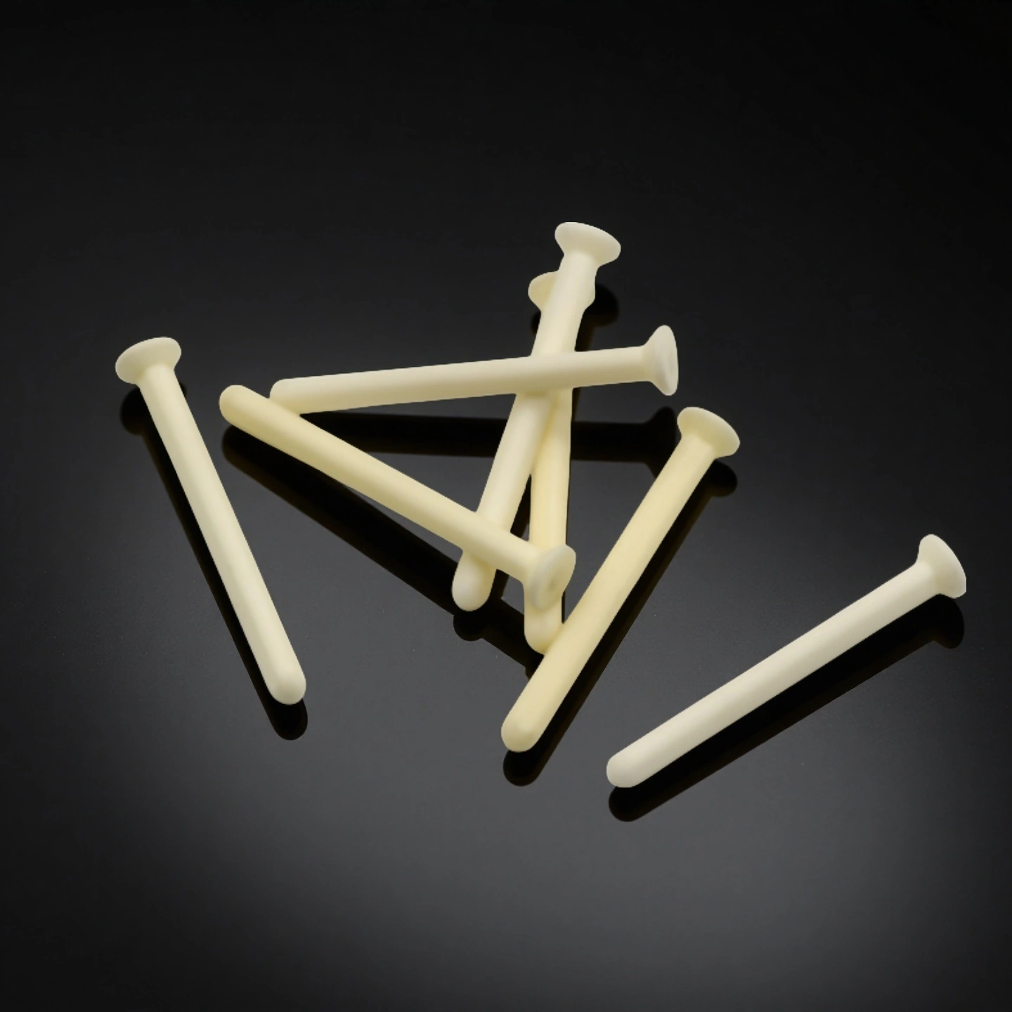
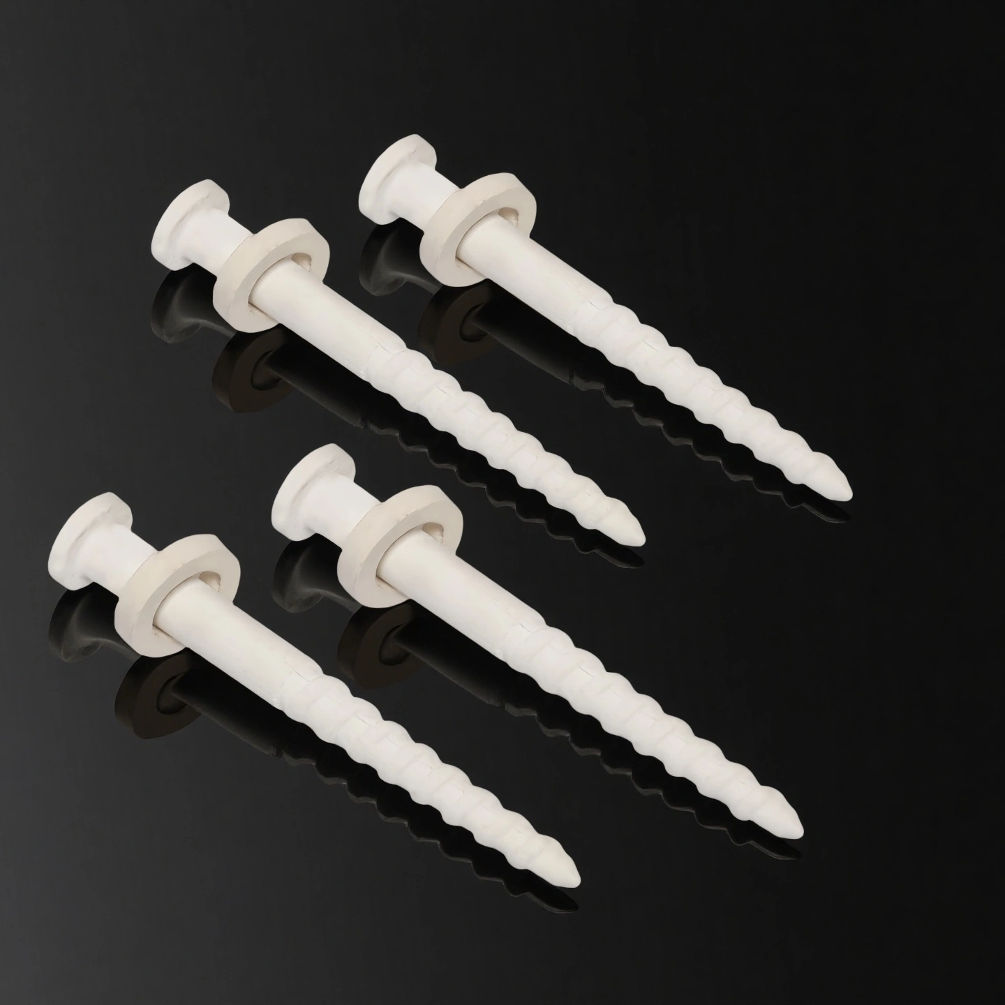
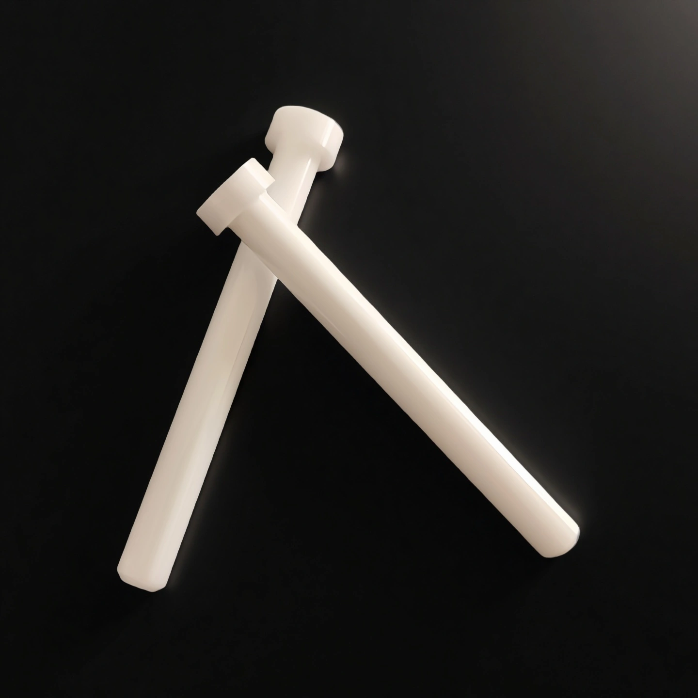
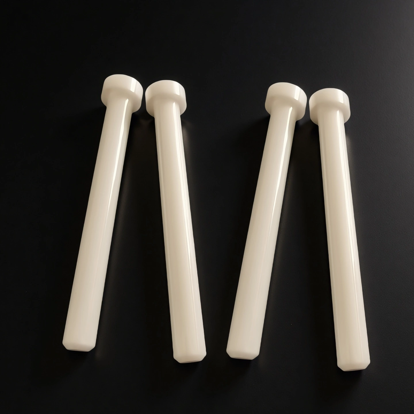
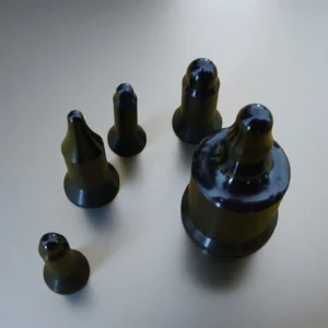
Alumina Ceramic Pin for Welding Fixtures and Automation

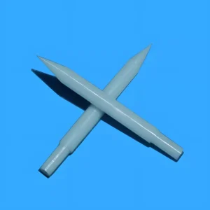
The alumina ceramic pin is used to connect, position, and fix workpieces in welding fixtures and mechanical assemblies. It prevents movement under heat and load, while providing electrical insulation and stable locating accuracy in high-temperature production environments.

Catalog No. AT-CP-L001
Material ≥ 95% Al2O3
Diameter Range Ø2mm – Ø20mm (±0.01–0.05mm available)
Max Operating Temperature 1600°C
Vickers hardness (HV) 1700–1800 HV (≈ 17–18 GPa)
Engineering RFQ Review
Small-Batch Custom Support
Factory-Direct Manufacturing
Drawing & Process Review

An alumina ceramic pin is a precision locating or electrically insulating component made from alumina (Al₂O₃) ceramic. It is used in welding fixtures, jigs, and automated tooling to locate, guide, or isolate parts where heat, electrical conductivity, metal spatter, or wear may limit conventional metal pins.

Engineering Advantages of Alumina Ceramic Pins

1. Electrical Insulation for Welding Fixtures

Alumina ceramic is electrically insulating and can be used to isolate locating features from the surrounding fixture in resistance and projection welding applications. The required insulation performance should be evaluated according to the pin geometry, voltage conditions, mounting design, and operating environment.

2. Wear and Weld-Spatter Resistance

The hard, dense ceramic surface provides resistance to abrasive wear and may reduce metal-spatter adhesion compared with uncoated steel under suitable welding conditions. Actual wear, cleaning frequency, and service life depend on weld proximity, contact pressure, alignment, and maintenance practices.

3. Dimensional Integrity in Elevated-Temperature Areas

Alumina retains hardness and dimensional integrity at temperatures where some metal locating pins may soften or deform. The allowable service temperature must still be confirmed according to the alumina grade, pin geometry, mechanical load, thermal cycling, and surrounding assembly.

4. Precision-Ground Locating Features

Critical diameters, shoulders, tapers, chamfers, and other locating features can be ground according to an approved drawing. Achievable tolerances depend on the pin size, geometry, surface-finish requirement, and inspection method.

5. Drawing-Based Replacement and Custom Geometry

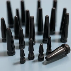
Straight, stepped, shouldered, tapered, grooved, or flatted pins can be reviewed from an existing drawing, 3D file, sample, or part photograph. Compatibility with an existing fixture must be confirmed from the mating dimensions, clearance, mounting method, load direction, and assembly sequence rather than assumed as a universal drop-in replacement.

Al2O3 Ceramic Pin Properties

Property Unit 96% Al₂O₃ 99% Al₂O₃ 99.5% Al₂O₃ 99.6% Al₂O₃ 99.7% Al₂O₃ 99.8% Al₂O₃ 99.9% Al₂O₃ 99.99% Al₂O₃
Alumina content % 96 99 99.5 99.6 99.7 99.8 99.9 99.99
Density g/cm³ 3.6-3.75 3.83 3.89 3.91 3.92 3.93 3.94 3.98
Color – white Ivory Ivory Ivory Ivory Ivory Ivory Ivory
Water absorption % 0 0 – 0 0 0 0 0
Young’s modulus (Elastic modulus) GPa 300 350 375 356 357 358 359 362
Shear modulus GPa – – 152 – – – – –
Bulk modulus GPa – – 228 – – – – –
Poisson’s ratio – – – 0.22 – – – – –
Compressive strength MPa 1910 2210 2500 2552 2554 2556 2558 2570
Flexural strength MPa 260 300 340 345 346 347 348 365
Fracture toughness MPa·m¹ᐟ² – – 4 – – – – –
Hardness GPa 14.5 17 17 23 24 25 26 30
Thermal conductivity W/m·K 20 31 31 31-33 31-33 31-33 31-35 31-35
Thermal shock resistance ΔT °C – – – 222 223 224 225 228
Maximum use temperature (no load) °C 1450 1680 ≤1750 1755 1760 1765 1770 1800
Coefficient of thermal expansion 10⁻⁶/°C 7.6 7.6 7.6 7.6 7.5 7.5 7.4 7.4
Volume resistivity Ω·cm >1×10¹⁴ >1×10¹⁴ >1×10¹⁴ >1×10¹⁴ >1×10¹⁴ >1×10¹⁴ >1×10¹⁴ >1×10¹⁴
Dielectric constant (relative permittivity) – 9.2 9.5 9.8 9.83 9.84 9.85 9.86 9.92
Dielectric strength kV/mm 15 19 16.9 23.2 23.4 23.6 23.8 24
Dissipation factor (loss factor @ 1 kHz) – – – 0.0002 – – – – –


Alumina Ceramic Pin Specifications

Type 1: Alumina Ceramic Pin with Thread
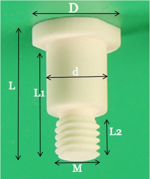
size of alumina ceramic pin

Alumina Ceramic Pin with Thread
Item No. D (mm) d (mm) L1(mm) L2 (mm) L(mm) M  Purity(%)
AT-CP-L001 6 4 7 3 9 M2 96-99
AT-CP-L002 7.5 5.5 25 16 29 M2.5 96-99
AT-CP-L003 8.6 6 65 40 70 M3 96-99
AT-CP-L004 9 7.5 50 35 55 M3 96-99
AT-CP-L005 10.5 9 43 27 47 M5 96-99
AT-CP-L006 11.8 8 67 42 72 M4 96-99
AT-CP-L007 12.5 8 52 33 56 M8 96-99
AT-CP-L008 15 10 46 24 50 M8 96-99
AT-CP-L009 16.4 11.5 80 40 84 M10 96-99
AT-CP-L010 18 14 53 35 57 M12 96-99
AT-CP-L011 21 15.5 45 35 48.5 M14 96-99
AT-CP-L012 23 16 32 22 36 M14 96-99


Type 2: Alumina Ceramic Pin without Thread
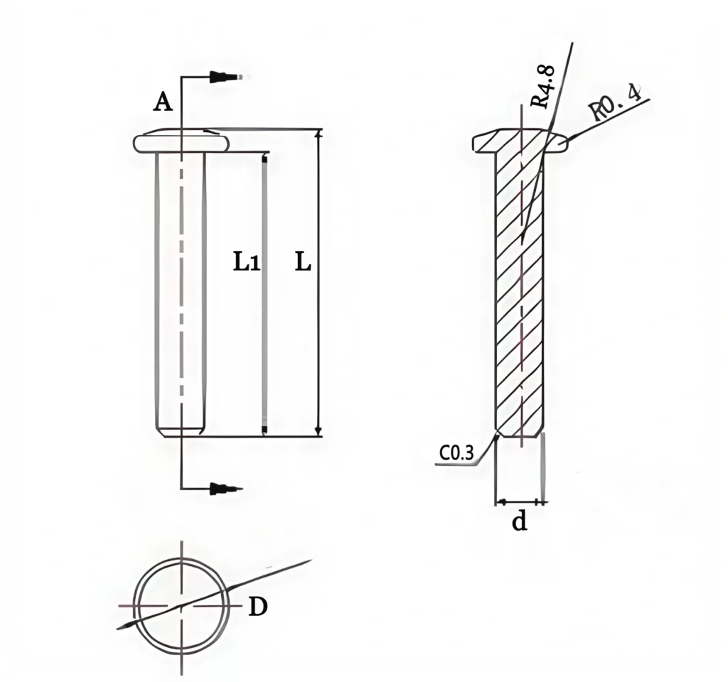
size of alumina ceramic pin 1

Alumina Ceramic Pin without Thread
Item No. D(mm) d (mm) L1 (mm) L (mm) Purity(%)
AT-CP-D001 8 6 9 11 96-99
AT-CP-D002 10 6 5 8 96-99
AT-CP-D003 11 5 13 16 96-99
AT-CP-D004 11.8 6.3 15 18 96-99
AT-CP-D005 12.6 8 16.5 20 96-99
AT-CP-D006 13.5 10 20 24 96-99
AT-CP-D007 15 10 14.5 17 96-99
AT-CP-D008 16.4 11 21 23 96-99
AT-CP-D009 18.5 14 40 45 96-99
AT-CP-D010 20 15 43 47 96-99
AT-CP-D011 24.2 16.2 52 56 96-99
AT-CP-D012 25 20 16 20 96-99
AT-CP-D013 30 18 40 46 96-99


Alumina Ceramic Pin Packaging

  • Each alumina ceramic pin is first wrapped or separated in protective blister cells or foam slots to prevent ceramic-to-ceramic contact during transport.
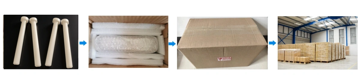
Alumina Ceramic Pin Packaging

Al2O3 Ceramic Pin Applications

  • Automotive Body and Chassis Welding Fixtures

    ✅Key Advantages

    1. Stable Positioning in High Cycle Nut Welding
    – The alumina ceramic pin maintains a consistent locating diameter after thousands of nut welding cycles, so body components keep the same hole and nut position.

    2. Reduced Fixture Downtime from Spatter Build-Up
    – The smoother ceramic surface collects less weld spatter than bare steel, which can cut cleaning intervals and reduce fixture stop time.

    3. Extended Fixture Component Life
    – The alumina ceramic pin operates at welding temperatures without softening or deforming, which allows the fixture to run more parts before a replacement is required.

    ✅ Problem Solved

    Suitability in body and chassis lines depends on weld schedule, side-load on the pin and mounting fit. For an accurate review, share the pin drawing or old-part photos with diameter, head shape, nut size context (M4–M12) and how the pin is retained in the fixture.
  • Welding Fixture and Automation Integrators

    ✅Key Advantages

    1. Flexible Geometry for Project-Based Jigs
    – The alumina ceramic locating pin can be produced in project-specific geometries so integrators can keep their fixture concepts while upgrading to ceramic hardware.

    2. Consistent Quality Across Repeat Projects
    – Once a design is validated, the same alumina ceramic pin specification can be reordered for future lines, which supports standardization across projects.

    3. Support for Mixed Material Tooling
    – The use of alumina pins together with steel and aluminum fixture components helps integrators manage thermal expansion and insulation requirements in complex tools.

    ✅ Problem Solved

    For project-based jigs, the review covers head geometry, stepped sections, mounting interface and whether heavy impact or thermal shock is expected — in severe-impact stations, a silicon nitride or zirconia pin may be the better route, and we advise accordingly instead of defaulting to alumina.
  • General Metal Fabrication and Component Welding

    ✅ Key Advantages

    1. Improved Repeatability in Small Batch Welding
    – The alumina ceramic pin keeps the same locating reference even when small batches with frequent changeovers are welded.

    2. Lower Maintenance Workload on Jigs
    – Ceramic locating surfaces reduce the need for frequent hand grinding and reworking of pins, which is important for workshops with limited maintenance staff.

    3. Compatibility with Existing Steel Fixtures
    – The alumina ceramic pin can be dimensioned to fit existing holes and sleeves in steel jigs, so workshops can upgrade step by step without new fixtures.

    ✅ Problem Solved

    In small-batch and mixed fabrication, confirm pin diameter, length, chamfer and how often pins are replaced today. Ceramic pins are sensitive to side impact and prying during installation, so the mounting method is always part of the engineering review.


Alumina Ceramic Pin Usage Instructions

  • Installation

    1. Install the alumina ceramic pin in a clean, aligned bushing or locator block. Do not force it into an undersized or misaligned hole.
    2. Use threaded retainers or clamps where possible. Avoid striking the ceramic tip or applying uncontrolled force.
    3. Ensure the support surface is clean and flat so the pin shoulder seats without bending or side loading.

  • Operation and In-Process Use

    1. Operate the pin within the approved temperature range and avoid sudden cooling after welding.
    2. Keep welding current and cycle time within the validated process conditions to prevent unnecessary overheating.
    3. Inspect locating edges and high-contact areas regularly for chips, cracks, or unusual wear.

  • Storage of Alumina Ceramic Pins

    1. Store spare pins in their protective packaging or separate compartments to prevent ceramic-to-ceramic contact.
    2. Keep them in a clean, dry area away from heavy tools or loose metal parts.

  • Cleaning and Maintenance

    1. Remove spatter with plastic or brass tools instead of steel scrapers.
    2. Use compatible cleaning agents when necessary, rinse thoroughly, and avoid prolonged exposure to aggressive solutions.
    3. Record inspection, cleaning, and replacement intervals to support maintenance planning.

  • Typical Misuse Points and Recommended Solutions

    1. Misuse: Installing the pin in a loose, undersized, or misaligned hole can create uneven support and cause cracking.
    Solution: Verify the bore diameter, alignment, and specified fit before installation.

    2. Misuse: Striking the ceramic tip with a steel hammer can chip the locating surface.
    Solution: Loosen the fixture before adjustment and use controlled clamping or soft-face tools.

    3. Misuse: Rapid cooling with coolant or cold compressed air can cause thermal-shock damage.
    Solution: Allow the pin to cool gradually and avoid contact with cold media while it is hot.

Frequently Asked Questions about Alumina Ceramic Pin

  1. Q: What is an alumina ceramic pin used for in welding fixtures?
    A: It works as a locating and insulating element in nut welding, projection welding and resistance welding fixtures — positioning the workpiece or nut while resisting weld spatter adhesion and blocking stray current paths through the fixture. The same pin family also serves as furnace lining pins in high-temperature equipment.
  2. Q: Can you make a ceramic pin to match my existing drawing or old pin?
    A: Yes, as an engineering-review item. Diameter, length, head shape, taper, steps and mounting features are reviewed from your drawing, sample or old-part photos before we confirm what we can make and the typical lead time — we do not confirm manufacturability without a drawing or sample.
  3. Q: How long does an alumina ceramic pin last compared with steel or coated pins?
    A: Service life depends on the station: weld schedule, side load, spatter exposure and mounting fit all matter. We do not quote fixed lifetime multiples; the practical approach is a small trial batch in your fixture, then scaling once the wear behaviour is confirmed.
  4. Q: Should I choose alumina, zirconia or silicon nitride for my station?
    A: Alumina covers insulation, wear and spatter resistance at a balanced cost. For severe side impact or strong thermal shock, silicon nitride or zirconia may be the better route — tell us the duty condition and the review will recommend a material instead of defaulting to alumina.
  5. Q: What tolerances can be held on the locating diameter?
    A: Typically ±0.05 mm, with tighter ground tolerances reviewed from the drawing and pin geometry before quotation. The achievable class for your specific pin is confirmed by review rather than promised as a blanket number.
  6. Q: What should my RFQ include for a fast, accurate reply?
    A: The key fields: application and whether the pin sits near the weld point, diameter, length, head or tip shape, steps or chamfers, mounting method, material purity need, temperature, insulation or anti-spatter requirement, quantity, and a drawing or old-part photos with the replacement reason.
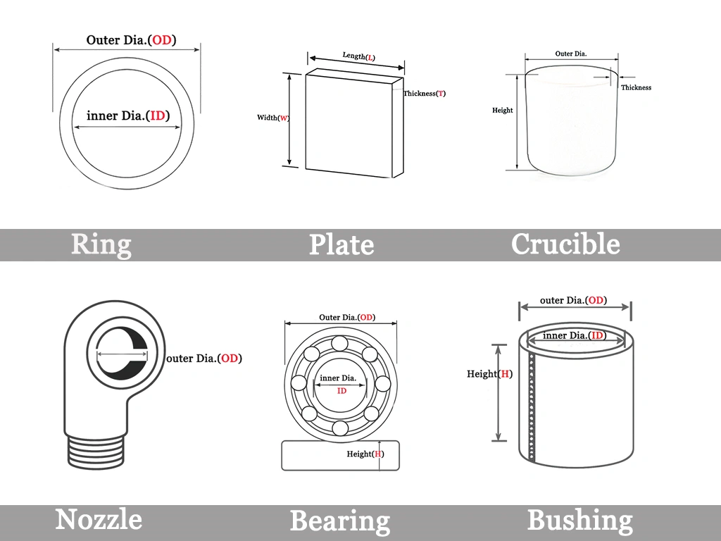
customize size

Custom Alumina Ceramic Pin Manufacturer

ADCERAX supports drawing-based manufacturing for alumina ceramic pins to match existing welding fixture designs while maintaining the functional advantages of technical ceramics.

  • Outer & Step Diameters: Tight tolerance control on locating diameters, typically within ±0.01–0.03 mm depending on pin size and geometry.
  • Overall Length & Engagement Length: Total pin length, shoulder position, and working engagement length can be defined to match jig layout and clamping space.
  • Tip Geometry: Flat end, chamfered end, conical tip, radius tip, or custom profiled tips for nut welding and stud welding positions.
  • Pin Structure: Cylindrical pins, stepped pins, and shouldered pins are compatible with existing bushings and locator sleeves.
  • Material Grade: Selection from 95% alumina for general welding fixtures to higher purity alumina for applications requiring stronger electrical insulation.
  • Surface Finish: As-fired surface for non-critical areas, and precision ground or polished surfaces on locating diameters and contact zones.
  • Anti-Rotation & Positioning Features: Optional grooves, flats, keyways, or anti-rotation details for fixed orientation in fixtures.
  • Drawing Format: Support for 2D technical drawings and 3D models, with engineering review for dimensional feasibility and manufacturability.

Related Products

ADCERAX - Your Trusted Advanced Ceramics Manufacturing Partner

Direct factory manufacturing with comprehensive ceramic materials expertise and global supply capabilities

China-Based Manufacturer

ADCERAX supplies ceramic components for overseas OEMs, equipment builders, and labs.

Custom Drawing Support

We review drawings, dimensions, materials, and application conditions before quotation.

Ceramic Process Control

Forming, sintering, machining, grinding, and finishing are arranged by part requirements.

Pre-Shipment Inspection

Dimensional checks, visual inspection, and packaging review help reduce procurement risk.

Get in Touch with Us

Our team will be happy to respond to you in less than 24 hours.

Pingxiang Factory — Silicon carbide, silicon nitride, high-temperature ceramics

Quick Quotation

*Our team will answer your inquiries within 24 hours.

*Your information will be kept strictly confidential.

Ready to Solve Your Engineering Challenge?

Partner with ADCERAX for reliable, high-performance advanced ceramic solutions. Our engineers are ready to discuss your project.

E-mail

info@adcerax.com

Phone

Tel: +86-0731-84428843 WhatsApp: +86 19311583352

Response Time

Within 24 hours

An alumina ceramic pin is a precision locating or electrically insulating component made from alumina (Al₂O₃) ceramic. It is used in welding fixtures, jigs, and automated tooling to locate, guide, or isolate parts where heat, electrical conductivity, metal spatter, or wear may limit conventional metal pins.

Engineering Advantages of Alumina Ceramic Pins

1. Electrical Insulation for Welding Fixtures

Alumina ceramic is electrically insulating and can be used to isolate locating features from the surrounding fixture in resistance and projection welding applications. The required insulation performance should be evaluated according to the pin geometry, voltage conditions, mounting design, and operating environment.

2. Wear and Weld-Spatter Resistance

The hard, dense ceramic surface provides resistance to abrasive wear and may reduce metal-spatter adhesion compared with uncoated steel under suitable welding conditions. Actual wear, cleaning frequency, and service life depend on weld proximity, contact pressure, alignment, and maintenance practices.

3. Dimensional Integrity in Elevated-Temperature Areas

Alumina retains hardness and dimensional integrity at temperatures where some metal locating pins may soften or deform. The allowable service temperature must still be confirmed according to the alumina grade, pin geometry, mechanical load, thermal cycling, and surrounding assembly.

4. Precision-Ground Locating Features

Critical diameters, shoulders, tapers, chamfers, and other locating features can be ground according to an approved drawing. Achievable tolerances depend on the pin size, geometry, surface-finish requirement, and inspection method.

5. Drawing-Based Replacement and Custom Geometry

Straight, stepped, shouldered, tapered, grooved, or flatted pins can be reviewed from an existing drawing, 3D file, sample, or part photograph. Compatibility with an existing fixture must be confirmed from the mating dimensions, clearance, mounting method, load direction, and assembly sequence rather than assumed as a universal drop-in replacement.

Al2O3 Ceramic Pin Properties

Property Unit 96% Al₂O₃ 99% Al₂O₃ 99.5% Al₂O₃ 99.6% Al₂O₃ 99.7% Al₂O₃ 99.8% Al₂O₃ 99.9% Al₂O₃ 99.99% Al₂O₃
Alumina content % 96 99 99.5 99.6 99.7 99.8 99.9 99.99
Density g/cm³ 3.6-3.75 3.83 3.89 3.91 3.92 3.93 3.94 3.98
Color – white Ivory Ivory Ivory Ivory Ivory Ivory Ivory
Water absorption % 0 0 – 0 0 0 0 0
Young’s modulus (Elastic modulus) GPa 300 350 375 356 357 358 359 362
Shear modulus GPa – – 152 – – – – –
Bulk modulus GPa – – 228 – – – – –
Poisson’s ratio – – – 0.22 – – – – –
Compressive strength MPa 1910 2210 2500 2552 2554 2556 2558 2570
Flexural strength MPa 260 300 340 345 346 347 348 365
Fracture toughness MPa·m¹ᐟ² – – 4 – – – – –
Hardness GPa 14.5 17 17 23 24 25 26 30
Thermal conductivity W/m·K 20 31 31 31-33 31-33 31-33 31-35 31-35
Thermal shock resistance ΔT °C – – – 222 223 224 225 228
Maximum use temperature (no load) °C 1450 1680 ≤1750 1755 1760 1765 1770 1800
Coefficient of thermal expansion 10⁻⁶/°C 7.6 7.6 7.6 7.6 7.5 7.5 7.4 7.4
Volume resistivity Ω·cm >1×10¹⁴ >1×10¹⁴ >1×10¹⁴ >1×10¹⁴ >1×10¹⁴ >1×10¹⁴ >1×10¹⁴ >1×10¹⁴
Dielectric constant (relative permittivity) – 9.2 9.5 9.8 9.83 9.84 9.85 9.86 9.92
Dielectric strength kV/mm 15 19 16.9 23.2 23.4 23.6 23.8 24
Dissipation factor (loss factor @ 1 kHz) – – – 0.0002 – – – – –


Alumina Ceramic Pin Specifications

Type 1: Alumina Ceramic Pin with Thread

size of alumina ceramic pin

Alumina Ceramic Pin with Thread
Item No. D (mm) d (mm) L1(mm) L2 (mm) L(mm) M  Purity(%)
AT-CP-L001 6 4 7 3 9 M2 96-99
AT-CP-L002 7.5 5.5 25 16 29 M2.5 96-99
AT-CP-L003 8.6 6 65 40 70 M3 96-99
AT-CP-L004 9 7.5 50 35 55 M3 96-99
AT-CP-L005 10.5 9 43 27 47 M5 96-99
AT-CP-L006 11.8 8 67 42 72 M4 96-99
AT-CP-L007 12.5 8 52 33 56 M8 96-99
AT-CP-L008 15 10 46 24 50 M8 96-99
AT-CP-L009 16.4 11.5 80 40 84 M10 96-99
AT-CP-L010 18 14 53 35 57 M12 96-99
AT-CP-L011 21 15.5 45 35 48.5 M14 96-99
AT-CP-L012 23 16 32 22 36 M14 96-99


Type 2: Alumina Ceramic Pin without Thread

size of alumina ceramic pin 1

Alumina Ceramic Pin without Thread
Item No. D(mm) d (mm) L1 (mm) L (mm) Purity(%)
AT-CP-D001 8 6 9 11 96-99
AT-CP-D002 10 6 5 8 96-99
AT-CP-D003 11 5 13 16 96-99
AT-CP-D004 11.8 6.3 15 18 96-99
AT-CP-D005 12.6 8 16.5 20 96-99
AT-CP-D006 13.5 10 20 24 96-99
AT-CP-D007 15 10 14.5 17 96-99
AT-CP-D008 16.4 11 21 23 96-99
AT-CP-D009 18.5 14 40 45 96-99
AT-CP-D010 20 15 43 47 96-99
AT-CP-D011 24.2 16.2 52 56 96-99
AT-CP-D012 25 20 16 20 96-99
AT-CP-D013 30 18 40 46 96-99


Alumina Ceramic Pin Packaging

  • Each alumina ceramic pin is first wrapped or separated in protective blister cells or foam slots to prevent ceramic-to-ceramic contact during transport.
Alumina Ceramic Pin Packaging

Quick Quote

The more details you provide, the faster we can quote.

*All inquiries are confidential.

Get Your Custom Solution

The more details you provide, the faster we can respond.

customize size

*We respond within 24 hours. All inquiries are confidential.

Download Catalog