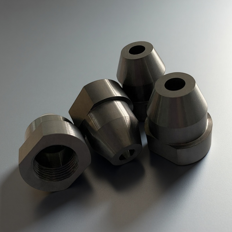
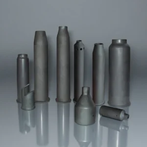
A silicon nitride nozzle is a precision ceramic flow component used to guide gas, liquid, solder, abrasive media, or hot process streams through a controlled bore. Compared with common alumina or metal nozzles, Si₃N₄ is selected when the outlet must keep its geometry under abrasive wear, thermal shock, or repeated heating and cooling.
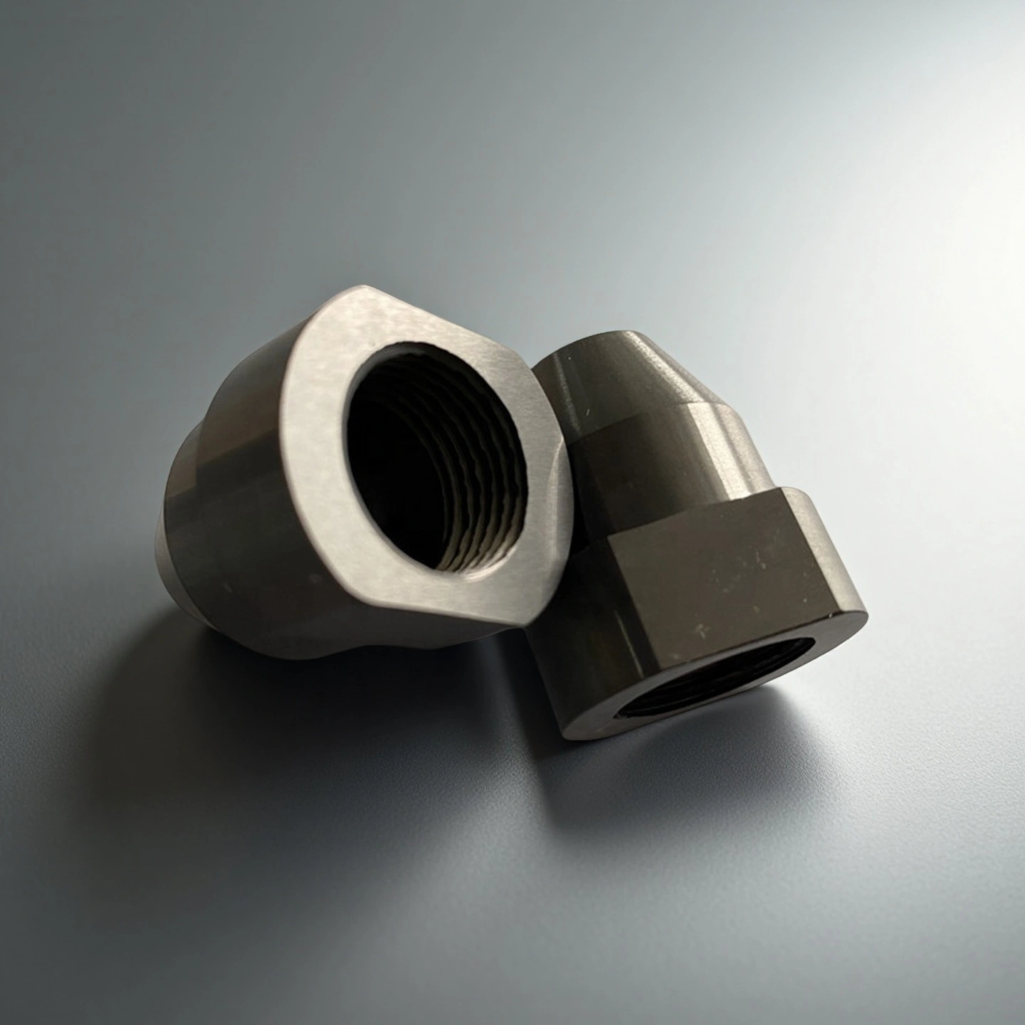
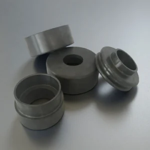
ADCERAX manufactures custom Si₃N₄ ceramic nozzles based on drawings, samples, or application requirements. Typical design points include bore diameter, inlet geometry, outlet edge shape, seat type, thread design, coaxiality, and surface finish.
Why Use Silicon Nitride for Nozzles?
Customer Concern
Why Si₃N₄ Helps
Bore enlargement during blasting
High hardness and good fracture toughness help slow orifice wear.
Edge chipping at the outlet
Silicon nitride has better toughness than many brittle ceramic alternatives.
Thermal shock during soldering or casting
Low thermal expansion helps reduce cracking during heating and cooling cycles.
Metal or solder buildup
Dense, smooth Si₃N₄ surfaces can reduce wetting and adhesion in suitable processes.
Multi-nozzle process variation
Controlled bore geometry and runout help maintain more consistent jet behavior.
Silicon Nitride vs. Other Nozzle Materials
Silicon nitride nozzles are often compared with alumina, silicon carbide, boron carbide, and tungsten carbide nozzles. Compared with these materials, Si₃N₄ offers a useful combination of toughness, low thermal expansion, wear resistance, and thermal shock stability, especially when nozzle bore geometry and outlet-edge durability are critical.
Brittle and costly; not ideal for all thermal cycling conditions.
Severe abrasive blasting where impact control is stable.
Tungsten Carbide
Excellent wear resistance and impact strength.
Heavy and electrically conductive; may corrode or wet in some processes.
Heavy-duty blasting and metal tooling environments.
Silicon Nitride Ceramic Nozzles Properties
Si3N4 Type
Gas pressure sintering Si3N4
Hot pressing sintering Si3N4
High thermal conductivity Si3N4
Density (g/cm3)
3.2
3.3
3.25
Flexural Strength (MPa)
700
900
600~800
Young Modulus (GPa)
300
300
300~320
Poisson's ratio
0.25
0.28
0.25
Compressive strength (MPa)
2500
3000
2500
Hardness (GPa)
15
16
15
Fracture toughness (MPa*m1/2)
5~7
6~8
6~7
Maximum working temperature (℃)
1100
1300
1100
Thermal conductivity (W/m*K)
20
25
80~100
Thermal expansion coefficient (/℃)
3*10-6
3.1*10-6
3*10-6
Thermal shock resistance (ΔT ℃)
550
800
/
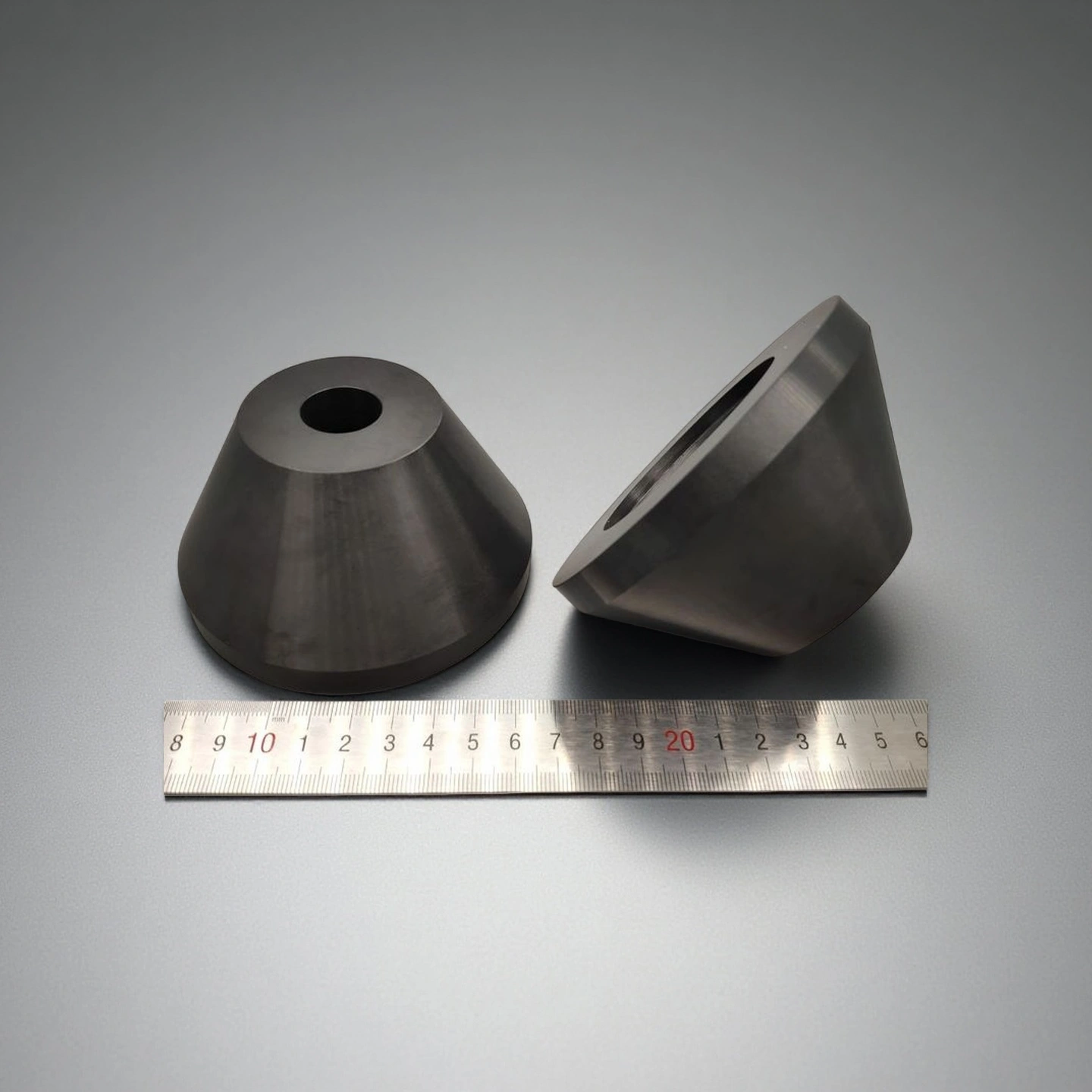
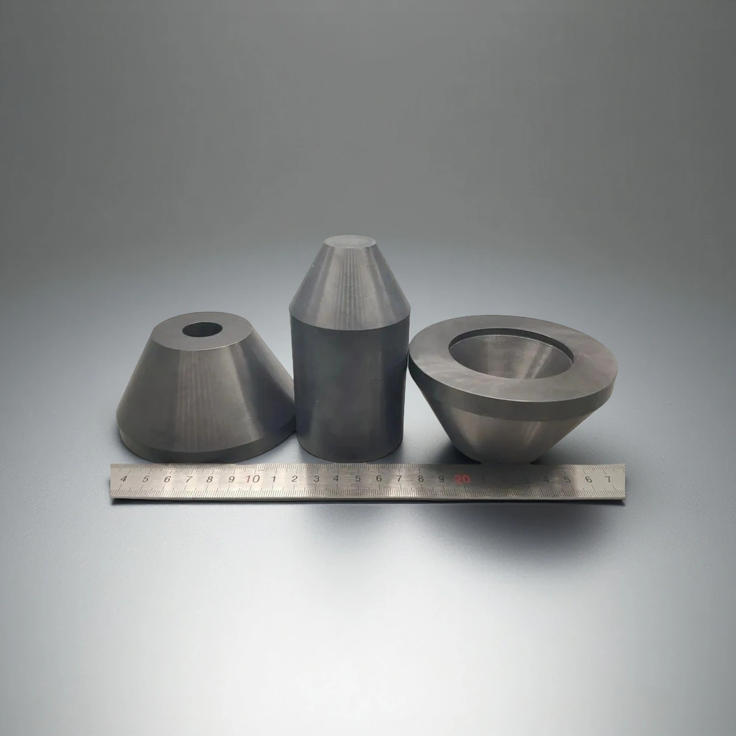
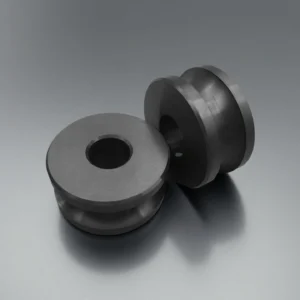
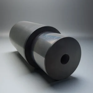
Si3N4 Nozzle Specifications
Silicon Nitride Nozzle
Item No.
Diameter(mm)
Height(mm)
AT-SIN-PZ1001
Customize
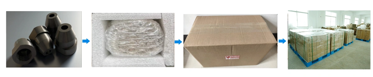
Silicon Nitride Nozzle Packaging
Silicon nitride nozzles are packed in separated foam cells or protective trays to reduce outlet-edge contact during transport. Oil-free bags help keep finished ceramic surfaces clean before installation.
Silicon Nitride Nozzle Applications
Silicon nitride nozzles are used in abrasive, thermal, soldering, and molten-metal environments where stable bore geometry, outlet-edge strength, and thermal cycling resistance are important. ADCERAX reviews each application based on media type, temperature, pressure, flow direction, mounting method, and required bore accuracy before recommending a nozzle design.
Abrasive Blasting
✅Application Fit
Suitable for abrasive media flow where bore enlargement, outlet wear, and jet consistency are key concerns.
✅Design Focus
Wear-resistant bore, chamfered outlet edge, stable ID control, and proper wall thickness.
Selective Soldering
✅Application Fit
Suitable for solder wave or solder jet systems that require stable jet height and reduced solder adhesion.
✅Design Focus
Polished outlet, low-wetting Si₃N₄ surface, controlled coaxiality, and repeatable seat fit.
Hot-Gas Spraying
✅Application Fit
Suitable for heated air, gas, or process streams where thermal cycling and flow stability are required.
Suitable for controlled gas or liquid flow where small-bore accuracy and repeatable jet direction matter.
✅ Design Focus
Straight or tapered bore, runout control, polished internal channel, and inspection-defined tolerance.
Silicon Nitride Ceramic Nozzle Usage Instructions
Proper installation, operation, storage, and cleaning help protect the ceramic bore, outlet edge, and seating surface. Actual process settings should be confirmed according to the equipment design, media type, temperature profile, mounting structure, and operating environment.
Installation
1. Seat Verification
Confirm whether the nozzle uses a threaded, slip-fit, stepped, or custom seat design before installation. The ceramic body should be supported evenly, and direct wrenching or metal impact on the ceramic surface should be avoided.
2. Coaxial Alignment
Align the nozzle bore with the holder, spindle, arm, or flow path during assembly. Poor alignment may cause unstable jet direction, uneven bore wear, outlet-edge damage, or local stress on the ceramic body.
3. Bore and Outlet Inspection
Check the inner bore, inlet edge, outlet face, thread, and seating surface before use. Nozzles with visible chips, cracks, deep scratches, or blocked flow paths should not be installed in production equipment.
4. Gasket / Seal Fit
Install sealing rings, O-rings, soft washers, or support pads evenly when they are required by the fixture design. Uneven sealing or point contact may concentrate stress around the ceramic seating edge.
Media and Flow Review
1. Media and Flow Review
Confirm the abrasive media, solder, molten metal, gas, liquid, or powder condition before operation. Oversized particles, debris, or unstable media flow may accelerate bore wear or cause partial blockage.
2. Temperature Control
Avoid sudden heating or cooling when the nozzle is used in soldering, hot-gas spraying, or molten-metal environments. Controlled temperature transition helps reduce thermal stress and lowers the risk of cracking.
3. Equipment Setting Check
Set jet height, air pressure, flow rate, stand-off distance, and spray direction according to the equipment manual and process requirement. Stable equipment settings help maintain consistent flow behavior and balanced nozzle wear.
4. Physical Protection
Avoid dropping, striking, or forcing the nozzle against metallic fixtures. Silicon nitride has high mechanical strength compared with many ceramics, but it remains a brittle material under impact or point loading.
5. Visual Monitoring
Inspect jet shape, spray angle, flow stability, and outlet condition during routine maintenance. Changes in jet behavior may indicate bore wear, residue buildup, misalignment, or partial blockage.
Storage
1. Protective Arrangement
Store silicon nitride nozzles individually in foam trays, plastic boxes, or separated compartments. The outlet edge and polished bore should not contact other ceramic, metal, or unfinished parts.
2. Clean Storage Environment
Keep finished nozzles in a clean, dry, and dust-controlled area before installation. Dust, hard particles, or mixed storage with metal parts may scratch the bore or damage the outlet edge.
3. Transport Protection
Use shock-absorbing packaging when shipping or moving precision nozzles. Heavy stacking, loose packing, or direct contact between parts should be avoided during transport.
Cleaning
1. Routine Cleaning
Clean the inlet and outlet with non-metallic rods, nylon brushes, soft swabs, or process-approved tools. Steel picks, hard blades, or aggressive scraping tools may scratch the bore or chip the outlet edge.
2. Residue Removal
For soldering or molten-metal applications, remove residue only after the nozzle has cooled under controlled conditions. A hot nozzle should not be quenched in cold solvent or water, as rapid cooling may create thermal stress.
3. Periodic Maintenance
If deeper cleaning is required, use a mild cleaning method approved by the process owner and allow the nozzle to dry completely before reinstallation. After cleaning, inspect the bore, outlet face, seat, and sealing surface again.
Silicon Nitride Ceramic Nozzles FAQ
Q: What is a silicon nitride nozzle used for? A: A silicon nitride nozzle is used to guide gas, liquid, solder, abrasive media, or hot process streams through a controlled ceramic bore. It is selected when stable orifice geometry, thermal shock resistance, and low-wetting behavior are required.
Q: Why choose silicon nitride instead of alumina for a nozzle? A: Silicon nitride has better fracture toughness and thermal shock resistance than many alumina grades, so it is more suitable for applications with impact, vibration, fast heating, or repeated thermal cycling.
Q: Is a Si₃N₄ nozzle suitable for selective soldering? A: Yes, when the grade and surface finish are selected correctly. Its dense and low-wetting surface helps reduce solder buildup and supports stable jet behavior during heating and cooling cycles.
Q: Can silicon nitride nozzles be used with molten aluminum? A: Silicon nitride can be suitable for molten aluminum contact because it has low wettability and good thermal shock behavior. Final suitability depends on alloy chemistry, temperature, contact time, and fixture design.
Q: What bore types can be customized? A: ADCERAX can review straight, tapered, Venturi, multi-step, and special transition bore designs. Bore profile should be selected according to pressure loss, jet focus, flow rate, and media characteristics.
Q: What tolerances can ADCERAX control? A: Typical tolerances depend on size, length, bore diameter, and geometry. ID, OD, length, runout, and surface finish should be confirmed during engineering review before production.
Q: What should I send for quotation? A: Please send a drawing, sample photo, bore size, tolerance, media type, operating temperature, interface design, surface finish requirement, quantity, and application background.
RFQ Checklist for Custom Silicon Nitride Nozzles
To help our engineering team review your nozzle design quickly, please send the following information when requesting a quotation.
Information Needed
Example
Drawing or sample photo
CAD, 2D drawing, or clear product image.
Bore diameter and tolerance
ID, OD, length, outlet angle, wall thickness.
Bore type
Straight, tapered, Venturi, multi-step, or special profile.
Media type
Abrasive grit, solder, molten metal, air, gas, liquid, or powder.
We design each silicon nitride nozzle to match the customer’s fixture, spray dynamics, and installation geometry. Every dimension and surface parameter can be specified for repeatable inspection and production traceability.
Custom Item
Available Options
Engineering Notes
Bore Geometry
Straight, tapered, Venturi, multi-step.
Bore profile affects pressure loss, jet focus, and media acceleration.
Bore Diameter
Custom ID based on drawing or flow requirement.
Small IDs require review of machining feasibility and inspection method.
Outlet Edge
Flat, chamfered, rounded, bevelled.
Outlet edge design affects spray pattern and chipping risk.
Interface
Threaded, slip-fit, flange, step shoulder.
Seat design should match the holder and avoid point loading on ceramic.
Surface Finish
Ground, polished, mirror-polished outlet.
Polished surfaces help reduce turbulence and residue buildup.