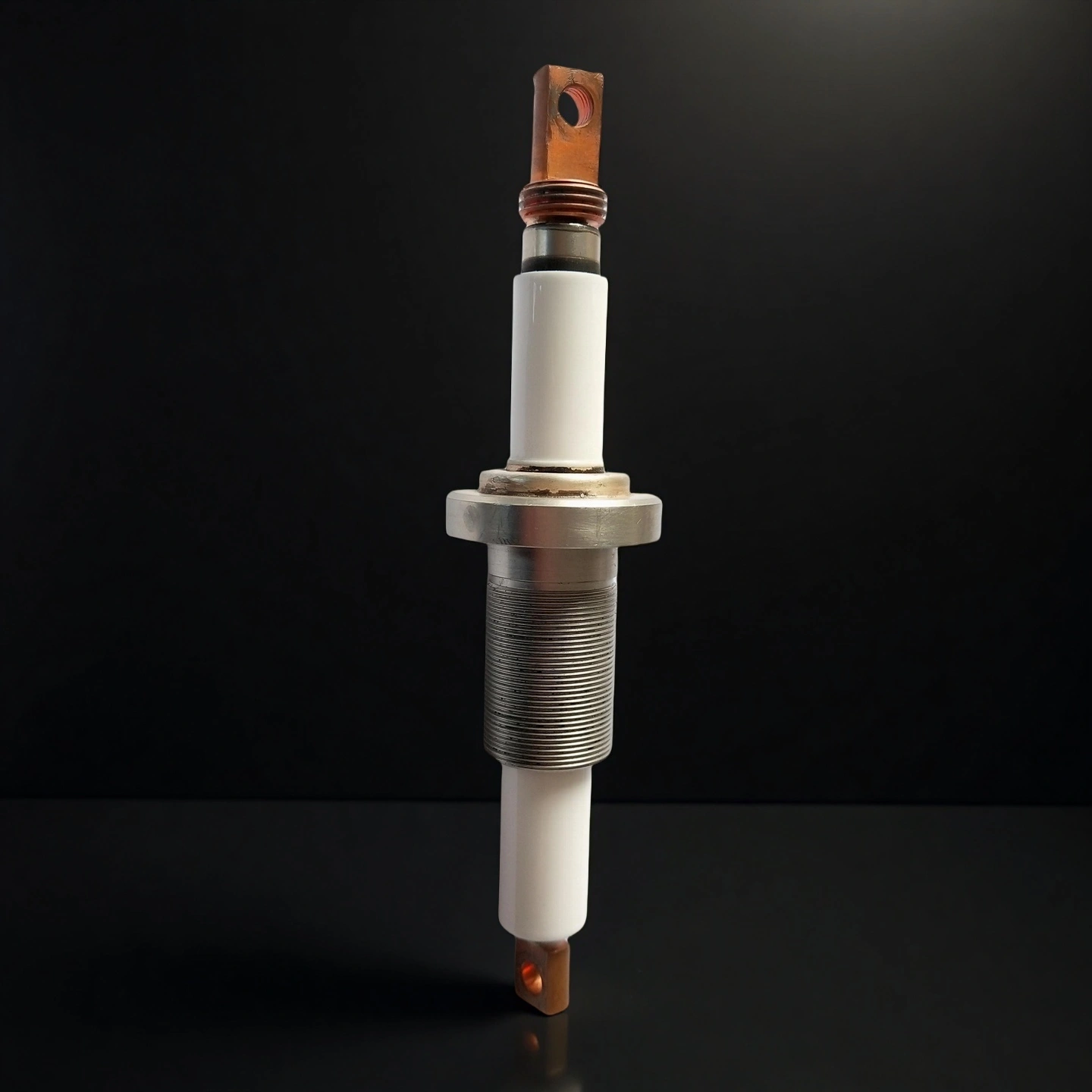
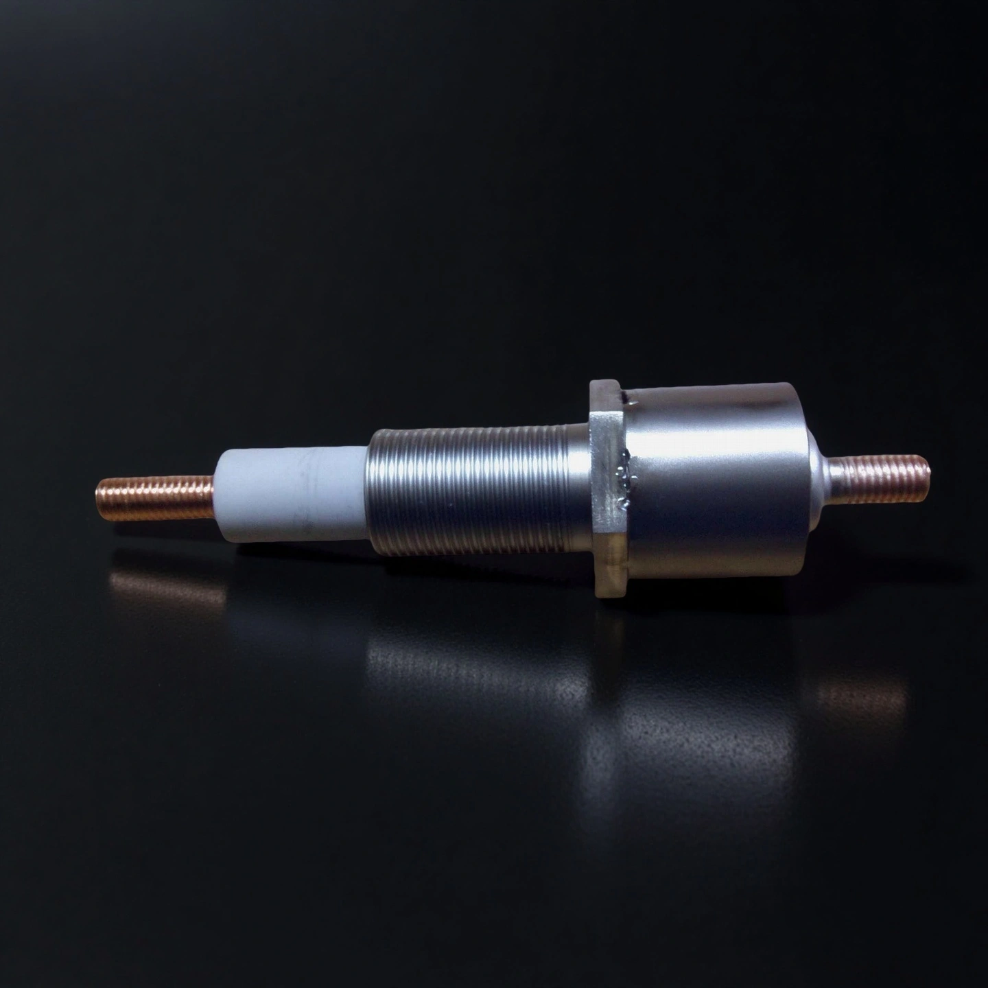
Ceramic electrode for vacuum coating machine is a high-voltage electrical feedthrough component designed to conduct power through the wall of a sealed vacuum chamber while maintaining electrical insulation and gas-tight integrity. It typically consists of a high-purity alumina (Al₂O₃) ceramic insulator brazed to a metal flange (CF, KF, or ISO type) and a central conductor made of copper, molybdenum, or Kovar alloy.
Ceramic Electrode for Vacuum Coating Machine Benefits
- Extended creepage geometry supports higher working voltage in compact flange sizes.
- Ceramic-to-metal brazed joint minimizes outgassing and supports high vacuum integrity.
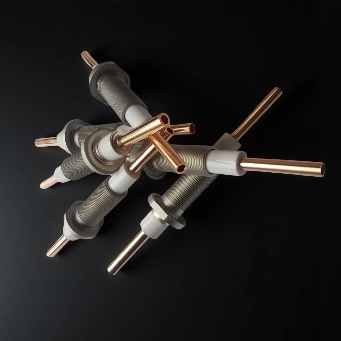
- Conductor choices (Cu/Mo/Kovar) balance current capacity with thermal/mechanical stability.
- Sealing faces are machined for consistent torque and repeatable installation alignment.
- Optional shielded or chamfered electrode tips to reduce local field concentration.
Ceramic Electrode for Vacuum Coating Machine Properties
- Voltage Resistance: up to 2 kV
- Current Capacity: up to 1000 A
- Leak Rate: < 1 × 10⁻¹⁰ Pa·L/s
- Baking Temperature Resistance: < 500 °C
- Tensile Strength: ≥ 120 MPa
- Mounting Thread Options: M24, M25, M28, M32, M33, etc.
- Electrode Rod Size & Connection Type: M6, M8, M10, M12 threads, or flat-type terminals
- Sealing Method: O-ring vacuum sealing
Ceramic Electrode for Vacuum Coating Machine Specifications
| Ceramic Electrode for Vacuum Coating Machine | ||
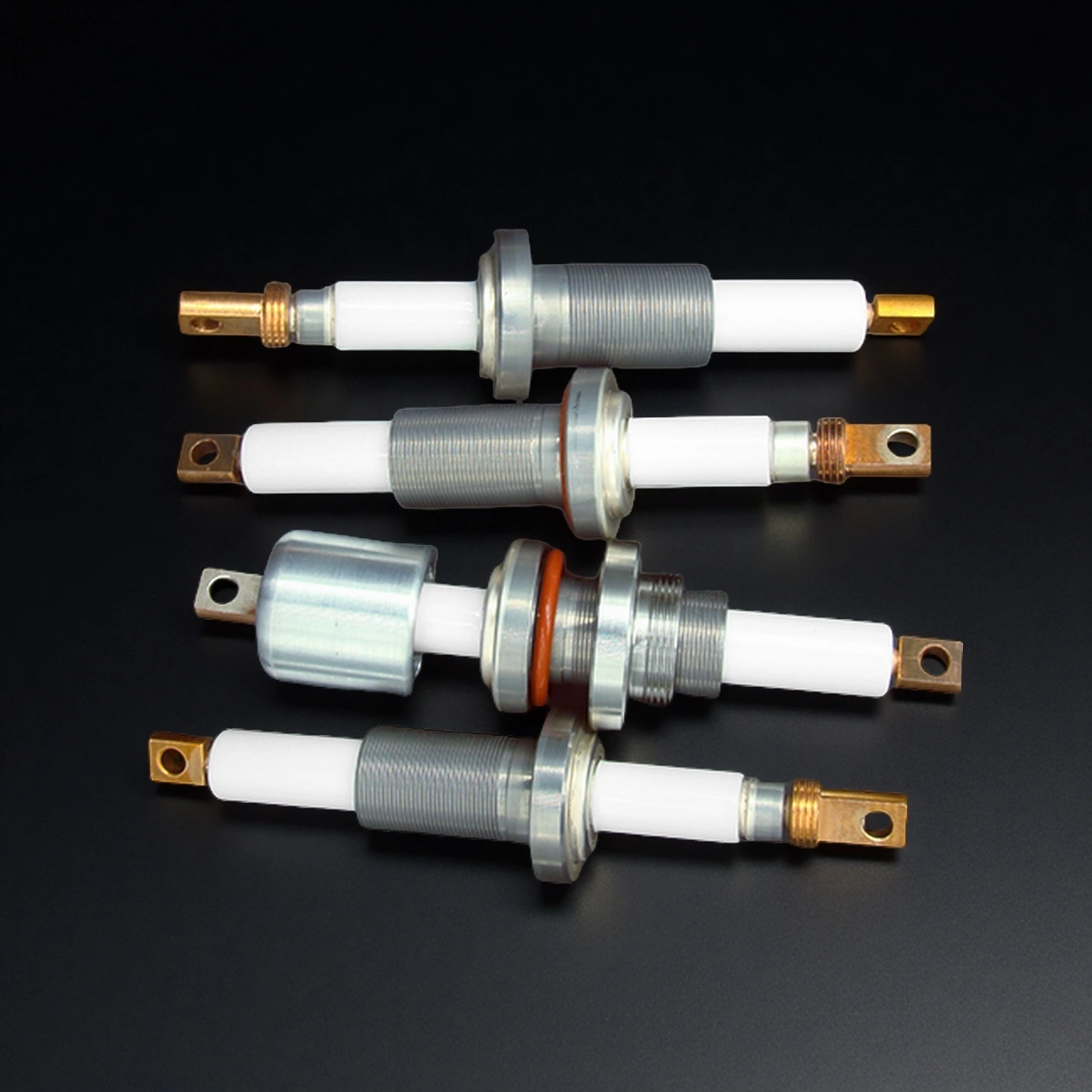
| Item NO. | Sealing seat thread | Electrode rod threaded/flat structure |
| AT-TCDJ-1001 | M24 | M8 |
| AT-TCDJ-1002 | M24 | flat structure |
| AT-TCDJ-1003 | M25 | M10 |
| AT-TCDJ-1004 | M25 | M6 |
| AT-TCDJ-1005 | M25 | flat structure |
| AT-TCDJ-1006 | M25 | M12 |
| AT-TCDJ-1007 | M28 | M10 |
| AT-TCDJ-1008 | M28 | M12 |
| AT-TCDJ-1009 | M32 | M8 |
| AT-TCDJ-1010 | M33 | flat structure |
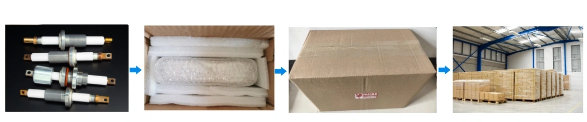
Ceramic Electrode for Vacuum Coating Machine Packaging
- Each ceramic electrode is individually packed in anti-static foam and sealed in plastic bags.
- Bulk orders are shipped in reinforced wooden crates with shock-absorbing inserts.