Ceramic Matrix Composites (CMC) — Custom Parts for High-Heat Environments
ADCERAX is a ceramic matrix composites manufacturer supplying CMC plates, panels, rings, tubes, sleeves, blocks and test coupons for high-temperature equipment and R&D. We work to drawing, align SiC/SiC, oxide-oxide, C/SiC or C/C routes with your operating window, and can combine CMC parts with our advanced ceramic portfolio for complete assemblies.
With engineering support, flexible small-batch sampling and stable repeat supply, we help you move from concept to reliable CMC hardware more quickly and with fewer iterations.
👆 Send us your drawing once, and turn it into a CMC component that keeps working where metals and standard ceramics fail.
What is Ceramic Matrix Composite?
Ceramic Matrix Composites Definition
Ceramic matrix composites (CMC) are fiber-reinforced ceramic materials in which a ceramic matrix such as silicon carbide or an oxide is combined with continuous fibers or woven fabrics to deliver load-bearing strength at high temperature with greater toughness than monolithic ceramics. By combining a ceramic matrix with SiC, carbon or oxide fibers, this architecture improves damage tolerance and thermal-shock resistance, so CMC materials can be used for structural components in demanding thermal and mechanical environments.
Ceramic Matrix Composites Structure
🔹Continuous ceramic phase (e.g. SiC, oxide ceramics) that carries load, gives stiffness and high-temperature capability.
🔹Fills the space between fibers and defines basic shape of the part.
🔹Continuous fibers, tows or woven fabrics (SiC fiber、carbon fiber、oxide fiber).
🔹Arranged as 2D cloth, 2.5D/3D woven preforms, braids or stitched stacks.
🔹Provide toughening and damage tolerance, help bridge cracks and resist catastrophic brittle fracture.
🔹A thin interphase coating around each fiber (e.g. BN、carbon or other engineered interface) controls bonding between fiber and matrix, allowing controlled debonding and crack deflection.
🔹External environmental barrier coatings (EBC) or protective layers may be added on the surface to improve oxidation and corrosion resistance in hot gas environments.
Ceramic Matrix Composites Properties
Ceramic matrix composite material properties are best defined as a combination of thermal behavior, mechanical performance, dimensional stability and inspection consistency, not a single datasheet value. We match the CMC route and lay-up to your operating temperature, atmosphere, load case and critical interfaces so the component performs as expected in service.
ceramic matrix composites physical properties
The physical properties of ceramic matrix composites support reliable operation where components see high temperature and repeated thermal cycling.
- High thermal stability helps CMC components maintain shape and stiffness under sustained elevated temperatures and steep thermal gradients.
- Controlled thermal expansion and good thermal shock resistance reduce cracking and distortion during rapid heat-up and cool-down cycles.
ceramic matrix composite mechanical properties
Mechanical properties of CMC components combine high-temperature strength with improved damage tolerance compared with many monolithic ceramics.
- Elevated-temperature strength and stiffness support load-bearing structures, brackets, panels and rings in demanding thermal conditions.
- Fiber reinforcement and engineered interfaces enhance toughness, slowing crack growth and helping components survive impact and cyclic loading.
ceramic matrix composites electrical properties
Electrical properties of ceramic matrix composites depend on the selected fiber and matrix system, allowing designers to target insulating or semi-conductive behavior.
- Oxide-based CMC materials can provide electrical insulation for components exposed to high temperatures and voltage differentials.
- Systems such as SiC/SiC or C/SiC offer tailored electrical conductivity or resistivity where controlled current paths or electromagnetic behavior are required.
ceramic matrix composites thermal properties
Ceramic matrix composites (CMCs) provide stable high-temperature thermal performance, managing heat flow, gradients, and thermal cycling with the right fiber–matrix system.
- CMCs can be tailored for heat management—from heat-spreading to thermal insulation—supporting controlled temperature profiles in hot-zone assemblies.
- Low thermal expansion and high thermal-shock tolerance help reduce cracking and distortion during thermal cycling, improving dimensional stability in service.
Advantages and Disadvantages of Ceramic Matrix Composites
🌟 Advantages of ceramic matrix composites
High-temperature capability – CMC components can retain stiffness and strength in temperature ranges where many metallic alloys creep, distort or require heavy cooling hardware.
Weight reduction – Lower density than typical heat-resistant alloys, enabling lighter hot-zone structures, rotating parts and support hardware.
Improved damage tolerance – Fiber reinforcement and engineered interfaces help deflect cracks and slow failure growth compared with monolithic ceramics, supporting safer, more gradual degradation modes.
Thermal shock and cycling resistance – Tailored lay-ups and matrix systems can better survive rapid heat-up / cool-down cycles and temperature gradients than many conventional ceramics.
Application-specific design freedom – Lay-up, fiber orientation and thickness can be tuned for local loads, clearances and stiffness, allowing more efficient structural designs.
⚠️ Disadvantages and limitations of ceramic matrix composites
Higher part cost – Fiber, processing and inspection steps make CMC components more expensive than standard ceramics or alloys in moderate-duty applications.
Longer qualification cycles – Material route selection, lay-up definition and test campaigns increase lead time before full adoption, especially in critical systems.
Manufacturing complexity – Not all geometries are practical; tight radii, abrupt thickness changes or deep pockets may require design compromises or multi-piece assemblies.
Processing and environment limits – Each system (SiC/SiC, oxide-oxide, C/SiC, C/C) has specific oxidation and atmosphere constraints; misuse outside the defined window can shorten service life.
Special handling and machining needs – Finishing operations often require dedicated tooling, dust control and inspection procedures, which can restrict supplier options and capacity.
Types of Ceramic Matrix Composite Materials
In our classification of ceramic matrix composites, we distinguish SiC/SiC and SiCf/SiC systems for high-temperature hot-gas parts, oxide-oxide CMCs for air-fired thermal structures, C/SiC CMCs for wear and friction components, and C/C composites for very high-temperature use in controlled atmospheres. This structure makes it easier to match each CMC category to your required temperature range, atmosphere and load case.
SiC/SiC Ceramic Matrix Composites
Silicon carbide matrix reinforced with silicon carbide fibres or fabrics
- Focus: high-temperature capability in demanding hot-gas and thermal environments.
- Strengths: good strength and stiffness at elevated temperatures, suitable for hot-section structural hardware.
- Typical use: shrouds, rings, panels and structural parts exposed to hot gases or high heat flux where weight reduction matters.
- When to consider: designs that push beyond conventional alloys and need a combination of heat resistance and structural performance.
Oxide-Oxide Ceramic Matrix Composites
Oxide fibre in an oxide ceramic matrix
- Focus: stability in oxidising atmospheres with straightforward storage and handling.
- Strengths: good environmental resistance in air and simple maintenance compared with many non-oxide systems.
- Typical use: panels, shields and supports in furnaces, process equipment and high-temperature insulation structures.
- When to consider: components operating in air at high temperature where oxidation resistance and dimensional stability are critical.
C/SiC Ceramic Matrix Composites
Carbon fibre in a silicon carbide matrix
- Focus: wear, friction and high-temperature mechanical loading.
- Strengths: good damage tolerance and friction behaviour, with the SiC matrix providing surface hardness and environmental protection.
- Typical use: friction discs, wear sleeves, contact parts and structural pieces that see sliding or braking forces at elevated temperature.
- When to consider: applications that combine mechanical contact, weight reduction and thermal exposure beyond the comfort zone of metallic solutions.
C/C Composites (Carbon/Carbon)
Carbon fibre in a carbon matrix
- Focus: very high-temperature environments, often in inert or vacuum atmospheres.
- Strengths: excellent thermal shock resistance and low density; often used as a reference option in high-temperature design discussions.
- Typical use: hot fixtures, structural blocks and special-purpose parts in controlled atmospheres.
- When to consider: designs that run at very high temperature in non-oxidising conditions and can accept the surface behaviour of carbon-based systems.
🎯Not sure which CMC route fits your furnace, turbine or process line?
ADCERAX can review your drawings and operating conditions, then recommend a suitable ceramic matrix composites type—SiC/SiC, SiCf/SiC, oxide-oxide, C/SiC or C/C—together with a practical lay-up, tolerance proposal and lead time. You get an application-matched CMC solution and a clear quotation you can move to sampling and production with confidence.
Application of Ceramic Matrix Composites
Ceramic matrix composites are selected when components must stay stable under heat, load and cycling where metals and standard ceramics reach their limits. The main applications of ceramic matrix composites span hot-zone hardware, wear and friction parts, structural elements and test pieces for high-temperature programs.
Industrial Furnaces and Thermal Processing Equipment
Uses of ceramic matrix composites
- Hot-zone structures and fixtures – SiC/SiC and oxide-oxide CMC panels, beams and support brackets for furnace interiors, kilns and thermal treatment lines.
- Shields and liners – Lightweight CMC plates used as radiation shields, burner surrounds and transition liners to reduce heat loss and extend maintenance intervals.
- Carrier and support components – Custom trays, rings and frames that hold parts during heat treatment, limiting distortion and improving cycle repeatability.
🔹 Examples of ceramic matrix composites
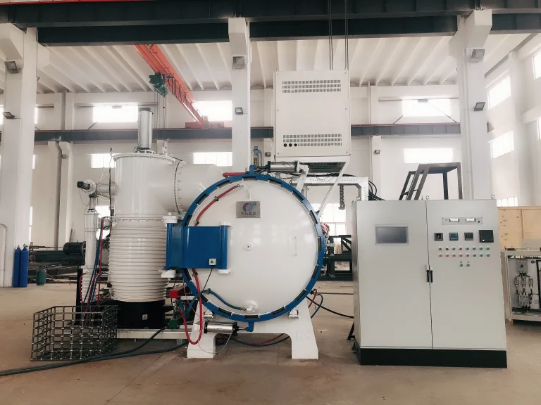
A heat-treatment OEM replaces heavy nickel-alloy fixtures in a vacuum furnace with SiC/SiC ceramic matrix composite beams and support plates. The new CMC hot-zone hardware cuts fixture weight by more than half, reduces thermal mass and shortens heat-up and cool-down time. As a result, operators can load larger batches per cycle while keeping distortion under control and extending fixture life compared with metallic designs.
Power, Energy and High-Temperature Gas Paths
Uses of ceramic matrix composites
- Hot gas path hardware – CMC rings, shrouds and flow-control elements in industrial gas turbines and high-temperature exhaust zones to handle elevated gas temperatures.
- Thermal protection elements – Insulating panels and segments that reduce cooling air demand and help improve efficiency in hot sections of energy systems.
- Sealing and interface parts – CMC seals and collars at critical joints where thermal gradients and movement make metal solutions difficult to keep tight.
🔹Examples of ceramic matrix composites
An energy equipment manufacturer introduces SiCf/SiC ceramic matrix composites shroud segments and seal parts into the hot-gas path of a mid-size industrial gas turbine. The CMC components allow higher firing temperature and reduced cooling air flow compared with traditional superalloy parts. Plant operators report improved efficiency and longer inspection intervals, while the lighter CMC hardware reduces rotor and casing loads during transients.
Wear, Friction and Motion Systems
Uses of ceramic matrix composites
Brake and friction components – C/SiC and C/C friction discs, pads and rings for high-energy stopping and repeated braking cycles at elevated temperature.
Wear sleeves and bushings – CMC sleeves and liners for shafts, guides and joints that see combined heat, sliding and load.
Gears and motion elements – Lightweight CMC gear segments and toothed rings in environments where lubricants are limited and temperatures are high.
🔹 Examples of ceramic matrix composites
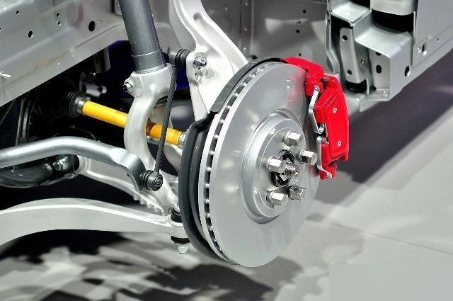
A braking system supplier develops C/SiC high-temperature composite materials discs and pads for high-performance vehicles and industrial test rigs. Compared with cast-iron discs, the C/SiC CMC friction set delivers far lower weight, maintains stable friction at repeated high-temperature stops and resists thermal cracking. In service, users see shorter stopping distances, less fade and longer disc life under aggressive braking cycles.
Process, Chemical and High-Temperature Flow Equipment
Uses of ceramic matrix composites:
- Tubes, nozzles and liners – CMC tubes and nozzle inserts in high-temperature, high-velocity or mildly corrosive flows where metal lifetime is limited.
- Structural plates and spacers – Panels and blocks that support refractories, insulation and metallic structures inside process vessels and ducts.
- Interface hardware – Flanges, collars and transition pieces that connect metallic systems to hot ceramic or refractory zones.
🔹Examples of ceramic matrix composites
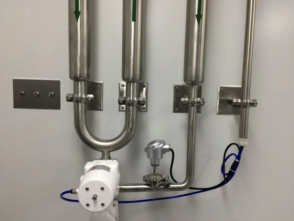
A chemical-process plant upgrades a hot gas transfer line by installing oxide-oxide and SiC/SiC ceramic matrix composites liners and nozzle inserts in the most exposed zones. The CMC components face hot, slightly corrosive gases and frequent thermal cycling. After the retrofit, inspection records show significantly reduced erosion and spalling compared with refractory-lined metal sections, and maintenance intervals between shutdowns are extended.
Process, Chemical and High-Temperature Flow Equipment
Uses of ceramic matrix composites:
- Tubes, nozzles and liners – CMC tubes and nozzle inserts in high-temperature, high-velocity or mildly corrosive flows where metal lifetime is limited.
- Structural plates and spacers – Panels and blocks that support refractories, insulation and metallic structures inside process vessels and ducts.
- Interface hardware – Flanges, collars and transition pieces that connect metallic systems to hot ceramic or refractory zones.
🔹Examples of ceramic matrix composites
A university laboratory and an industrial partner run a joint program using standard SiC/SiC and C/SiC ceramic matrix composites coupons plus a small batch of prototype rings and panels. The coupons are used to map tensile, fatigue and oxidation behavior under different atmospheres, while the prototype parts are exposed in a burner rig that simulates real hot-section conditions. The resulting data set supports finite-element models and de-risks the later transition to production-grade CMC hardware.
Custom ceramic matrix composites supplier
We specialize in custom ceramic matrix composites parts made to your drawings, samples or application conditions. CMC plates, panels, rings, tubes and sleeves can be tailored in thickness, geometry and lay-up, with typical lead times of 3–9 weeks depending on complexity and inspection level.
Customization Options
Extra-large / Extra-small diameters, non-standard thicknesses, and ultra-long / ultra-short lengths.
Provide higher - level dimensional accuracy and concentricity control than the standard.
Flanges, steps, threads, drilling holes, grooves, etc.
Adjust the material according to the application requirements.
Polish and grind the surface to achieve a specific surface roughness.
Customization Process
Send us your drawing, CAD file, or physical sample with material grade, dimensions, tolerances, and quantity. Our engineers will evaluate the design and provide a detailed quotation with lead time and pricing.
Once the quote is approved, we proceed with sample prototyping (1–50 pcs) if needed, for testing and validation.
After sample approval or direct confirmation, we begin batch manufacturing using CNC machining, sintering, and polishing. All parts undergo dimensional checks, material purity testing, and surface finish inspection.
Finished products are securely packed and shipped via DHL/FedEx/UPS or your preferred method. We support global delivery with full documentation.
Why Choose ADCERAX as Your Ceramic Matrix Composite Manufacturer?
ADCERAX is a ceramic matrix composites manufacturer in China, providing factory-direct pricing, engineering support and flexible customization from blanks to finished parts. With controlled tolerances and reliable global shipping, we make sourcing fibre-reinforced ceramic composite components straightforward and low risk.
Competitive pricing with strict quality control from raw material sourcing to final delivery
Professional team providing comprehensive technical support and collaborative design
Small batch orders to large-scale production with complex geometries and tight tolerances
24-hour response and 24-hour dispatch for standard items, 3-7 weeks for custom orders.
China Ceramic Matrix Composite Factory-ADCERAX
ADCERAX has worked in advanced ceramics for over 20 years and has developed more than 2,000 types of precision parts, now extending this experience into ceramic matrix composites components for demanding thermal and structural applications.
With engineering support from prototype to repeat supply, ADCERAX helps you validate designs faster, define practical tolerances and process windows, and then move smoothly into stable batch production. Simply share your operating conditions and drawings, and we can replace vulnerable locations with suitable CMC components so these critical areas remain reliable under high temperature and thermal shock.
Ceramic Matrix Composite Manufacturing
CMC ceramic matrix composite parts behave like brittle, fibre-reinforced engineering ceramics during processing. Successful manufacturing controls lay-up, densification and final machining to produce clean, repeatable features and stable dimensions without microcracks that reduce service life.
Tooling and Machine Setup
💡Machine choice
- Rigid 3- to 5-axis CNC machines with good spindle condition and solid fixturing are required for most ceramic matrix composite machining.
- Use enclosed machines with effective dust extraction to control CMC fibre and ceramic dust.
- High-speed machining centres or dedicated grinding machines are reserved for tight-tolerance or fine-surface areas.
💡Tooling selection
- Prefer diamond-coated carbide, PCD or CBN tools with positive rake to reduce cutting forces in SiC/SiCf, C/SiC and oxide-oxide CMCs.
- Use stable toolholders with minimal overhang to limit vibration and edge chipping.
- Choose small nose radii and fine-pitch cutters when finishing edges and holes on thin CMC sections.
💡Cutting conditions
- Start with light depths of cut and moderate feeds; increase gradually while monitoring edge quality and temperature.
- Use mist or air blast where possible; avoid heavy flood coolant that can cause thermal shock on hot CMC parts.
- Keep chips and dust cleared from the cutting zone to prevent re-cutting and surface damage.
Process Recommendations
💡Turning and grooving
- Use smooth tool entry and exit, avoiding sudden plunges into sharp corners on CMC rings and sleeves.
- Leave small radii at groove bottoms and shoulders to reduce stress concentration and improve tool and part life.
💡Milling and pocketing
- Prefer climb milling with light radial engagement to minimise edge chipping along CMC plate and panel walls.
- Ramp or helix into pockets instead of full-width plunging to reduce impact loading on the cutting edge.
💡Drilling and threading
- Peck drilling with controlled chip removal reduces the risk of cracks at the hole exit in ceramic matrix composites.
- For threads, consider thread milling or carefully controlled tapping with generous run-out and deburring of starts.
💡Grinding / ultrasonic assistance
- Use fine-grit diamond grinding for tight-tolerance faces and critical sealing surfaces.
- Ultrasonic-assisted machining can help on very small holes or delicate features but is usually limited to special cases.
Tips-for-Machining (DFM)
💡Avoid knife-edge features
- Keep minimum wall thickness and land widths above agreed limits; extremely sharp fins and edges in CMC parts are prone to chipping.
💡Use radii and chamfers wisely
- Add small corner radii or chamfers wherever possible to reduce stress concentrations and improve edge strength, especially around slots, pockets and bolt holes.
💡Separate critical and non-critical tolerances
- Tighten tolerances only where function requires it and relax non-critical dimensions; this reduces machining time, scrap risk and CMC machining cost.
💡Plan fixturing surfaces
Include flat reference pads or clamping areas so the ceramic matrix composite component can be held securely without stressing functional sections.
Consider leaving sacrificial stock for clamping on prototypes and removing it in the final machining step.
ADCERAX Ceramic Matrix Composites Processing Capabilities
ADCERAX combines engineering support, route selection and CNC machining assets dedicated to ceramic matrix composites CMC. We turn SiC/SiC, SiCf/SiC, oxide-oxide, C/SiC and C/C blanks into finished CMC components with stable quality for demanding industrial and R&D equipment.
| Capability Category | Equipment / Specification | Engineering Value Provided |
|---|---|---|
| CMC Blank Preparation & Fixturing | CMC plates, panels, tubes and rings prepared with dedicated fixtures and dust-control systems | Stable reference surfaces and secure clamping that allow repeatable ceramic matrix composites processing |
| Precision CNC Machining of CMC Parts | 3–5 axis CNC machining centres with diamond tooling and rigid workholding for CMC materials | Accurate outside profiles, steps and bevels with controlled distortion and edge quality |
| CMC Grinding & Surface Finishing | Surface and rotary grinders, fine-grit diamond wheels, lapping and polishing fixtures | Tight flatness and parallelism, sealing faces and mating surfaces suitable for hot-zone and structural assemblies |
| Hole, Slot & Thread Machining in CMC | CNC drilling, countersinking, thread milling, small-diameter diamond tools | Clean holes, slots and threaded features in ceramic matrix composites with minimal chipping and good positional TIR |
| Prototype & Small-Batch CMC Production Runs | Flexible fixture concepts, quick-change tooling, mixed-material setups | Short lead times for samples and engineering trials before moving to repeat CMC production |
| CMC Metrology, Inspection & Documentation | CMM, optical measurement, thickness gauges and dedicated CMC inspection jigs | Verified tolerances, recorded dimensions and batch documentation to support ongoing ceramic matrix composites supply |
Ceramic-matrix Composites Quality & Certifications
FAQs About Ceramic Matrix Composite CMC
1. Basic concept
Conventional ceramics: Single, monolithic ceramic body. Once a crack starts, it can run straight through the material.
Ceramic Matrix Composite Material: A ceramic matrix reinforced with continuous fibres or fabrics – this is the practical ceramic matrix composites definition used in engineering. Fibres bridge and deflect cracks so failure is slower and more controllable.
2. Behaviour in service
Conventional ceramics: High stiffness and hardness, but brittle, poor thermal-shock resistance, often limited under cyclic loading.
CMC materials: Key ceramic matrix composites properties include higher damage tolerance, better thermal-shock performance and more stable behaviour under temperature gradients and cycling.
3. Where each one fits
Conventional ceramics: Good for static, moderate-risk parts with simple loading.
CMC: Chosen when the advantages and disadvantages of ceramic matrix composites balance in favour of reliability at high temperature, even if the part and processing cost are higher.
A common classification of ceramic matrix composites is by matrix–fibre system: SiC/SiC or SiCf/SiC, oxide-oxide CMC, C/SiC and C/C. For project discussions we usually group them by application window, such as hot-gas path components, oxide-based structural parts, friction components and very high-temperature C/C parts.
Compared to other ceramic materials, ceramic-matrix composites have better damage tolerance, higher resistance to thermal shock, and lower density at a given temperature capability. Versus metals, they can operate at higher temperatures with reduced cooling requirements and less creep.
We need your target operating temperature and atmosphere, load case and safety factors, expected thermal cycling, available space, and interface details with metals or other ceramics. Drawings, sketches or photos of the current design also help us choose the right CMC route and lay-up.
Key properties include usable temperature window, oxidation resistance, tensile and flexural strength, fracture toughness, thermal conductivity, thermal expansion and fatigue behaviour. For many design reviews we first match temperature and environment, then refine based on strength, stiffness and joining method.
Toughening mechanisms for ceramic matrix composites are built around how fibres, matrix and interfaces work together to slow and control cracking, instead of letting a single crack cause sudden failure as in monolithic ceramics. Key mechanisms include:
Fibre bridging and pull-out
Continuous fibres or fabrics bridge across a growing crack. As the crack opens, fibres stretch and then gradually pull out, absorbing energy instead of letting the part snap abruptly.Controlled fibre–matrix debonding
A designed interface layer between fibre and matrix (for example a BN or carbon interphase) allows partial debonding. This makes the crack change path and lose energy, which is a core toughening mechanism for ceramic matrix composites.Crack deflection and branching
When a crack meets fibres, interfaces or plies, it is deflected, branched or forced to follow a longer, more tortuous path. This reduces the driving force for rapid crack growth.Multiple microcracking instead of one critical crack
CMC laminates are designed so many fine cracks form and stabilise before any single crack becomes critical. This “graceful” damage pattern provides warning and more stable behaviour under load and thermal cycling.
Together, these mechanisms give ceramic matrix composites higher damage tolerance and better thermal-shock performance than conventional ceramics, making them more suitable for demanding structural and high-temperature applications.
Ceramic matrix composites processing methods combine fibre preforms with different matrix densification routes and finishing steps. In practice, most CMC parts are produced using one or a tailored combination of the following:
Chemical Vapour Infiltration (CVI)
Gas-phase precursors infiltrate a porous fibre preform and deposit a ceramic matrix (often SiC). CVI is widely used for high-performance SiC/SiC and SiCf/SiC components.Polymer Infiltration and Pyrolysis (PIP)
The fibre preform is repeatedly impregnated with a ceramic-forming polymer and then pyrolysed to form a ceramic matrix. PIP is flexible and often combined with CVI to balance density, cost and cycle time.Melt or Reactive Infiltration
A molten silicon or metal phase infiltrates a carbon or ceramic preform and reacts to form the matrix, commonly used for C/SiC systems to achieve high density in fewer cycles.Slurry / Sol–Gel Infiltration for Oxide CMCs
Oxide-oxide ceramic matrix composites often use slurry or sol–gel impregnation plus sintering to build the oxide matrix around the fibres.Post-processing and machining
After densification, near-net CMC shapes are finish-machined with diamond tooling, ground, inspected and, where needed, coated (for example with environmental barrier coatings) to meet final tolerance and service requirements.
A dimensioned drawing with tolerances, material preference (if any), surface-finish requirements, quantity per batch and expected annual volume are essential. If you are still evaluating, we can also work from a 3D model plus notes on the operating conditions to propose a CMC solution.
Pricing is mainly driven by CMC system, part geometry, machining complexity, inspection level and order quantity. Components that require complex preforms, deep pockets or extensive grinding and NDT will be more expensive than simpler plates, rings or tubes.
When forming ceramic matrix composites, the goal is not just “making a part,” but achieving a balanced set of ceramic matrix composites properties that work in real service. Key objectives include:
Build the right internal architecture
Create a controlled fibre preform and lay-up (SiC/SiC, SiCf/SiC, oxide-oxide, C/SiC, C/C) so stiffness, strength and damage tolerance match the design load paths.
Achieve sufficient densification without damaging fibres
Use suitable ceramic matrix composites processing methods (CVI, PIP, melt infiltration, slurry routes) to reach the required density and porosity levels while preserving fibre integrity and interface behaviour.
Control damage tolerance and crack behaviour
Design interfaces so cracks deflect, fibres bridge and pull out, and damage grows in a stable, gradual way instead of sudden brittle failure as in monolithic ceramics.
Deliver dimensional stability and machinability
Form and densify components so that final machining can achieve critical tolerances, flatness and concentricity without excessive chipping or distortion.
Match the application window
Ensure the chosen CMC route meets the target temperature, atmosphere and cycling conditions for its intended application of ceramic matrix composites, with a realistic balance of cost, risk and lifetime.
Get in touch with us
We believe that Adcerax will become your best partner!
Please fill in your contact information in the form or call us.
*Our team will answer your inquiries within 24 hours.
*Your information will be kept strictly confidential.
info@adcerax.com
Telephone: +(86) 0731-74427743
WhatsApp: +(86) 19311583352
Within 24 hours