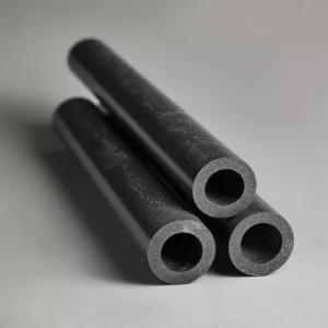
What Is a Nitride Bonded Silicon Carbide Beam?
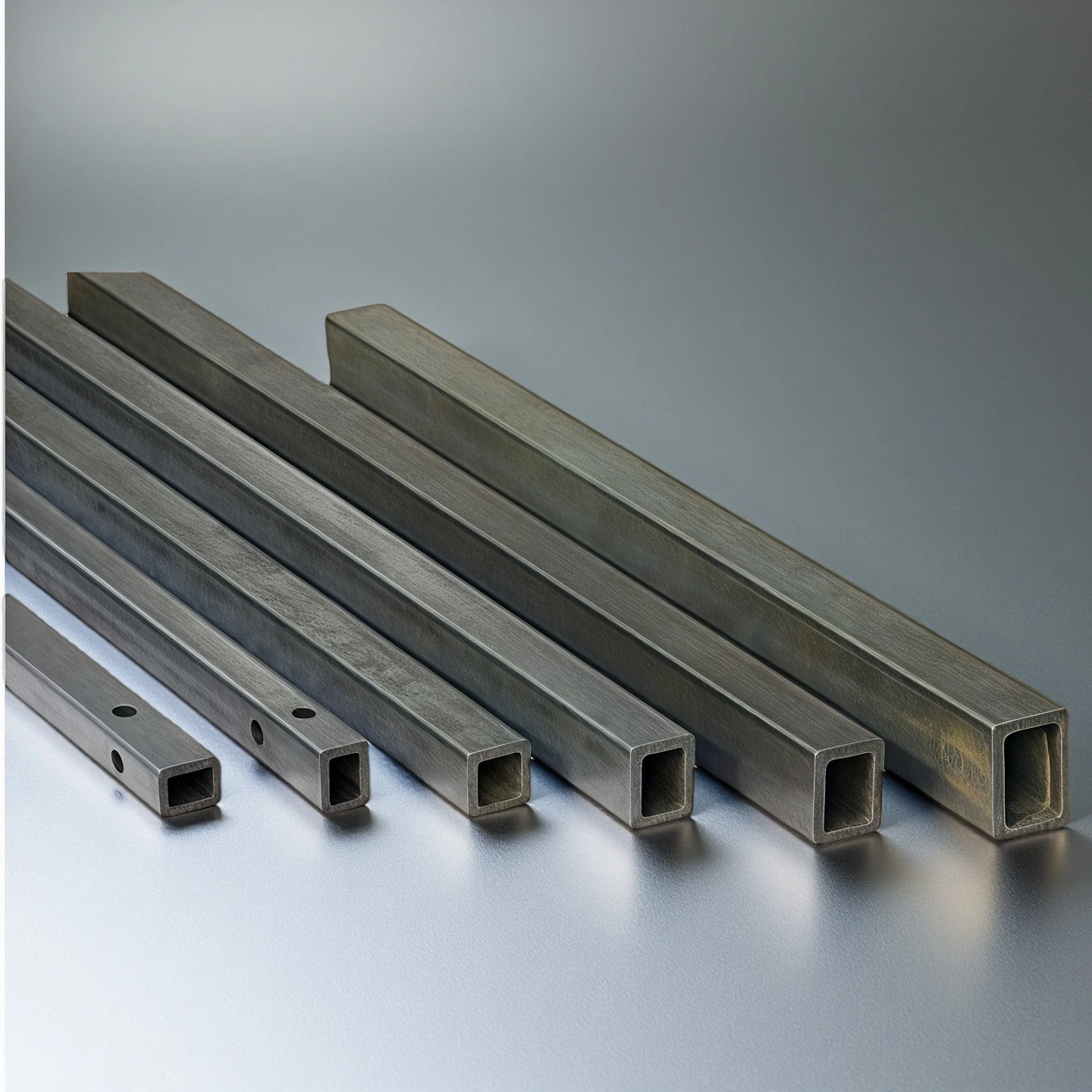
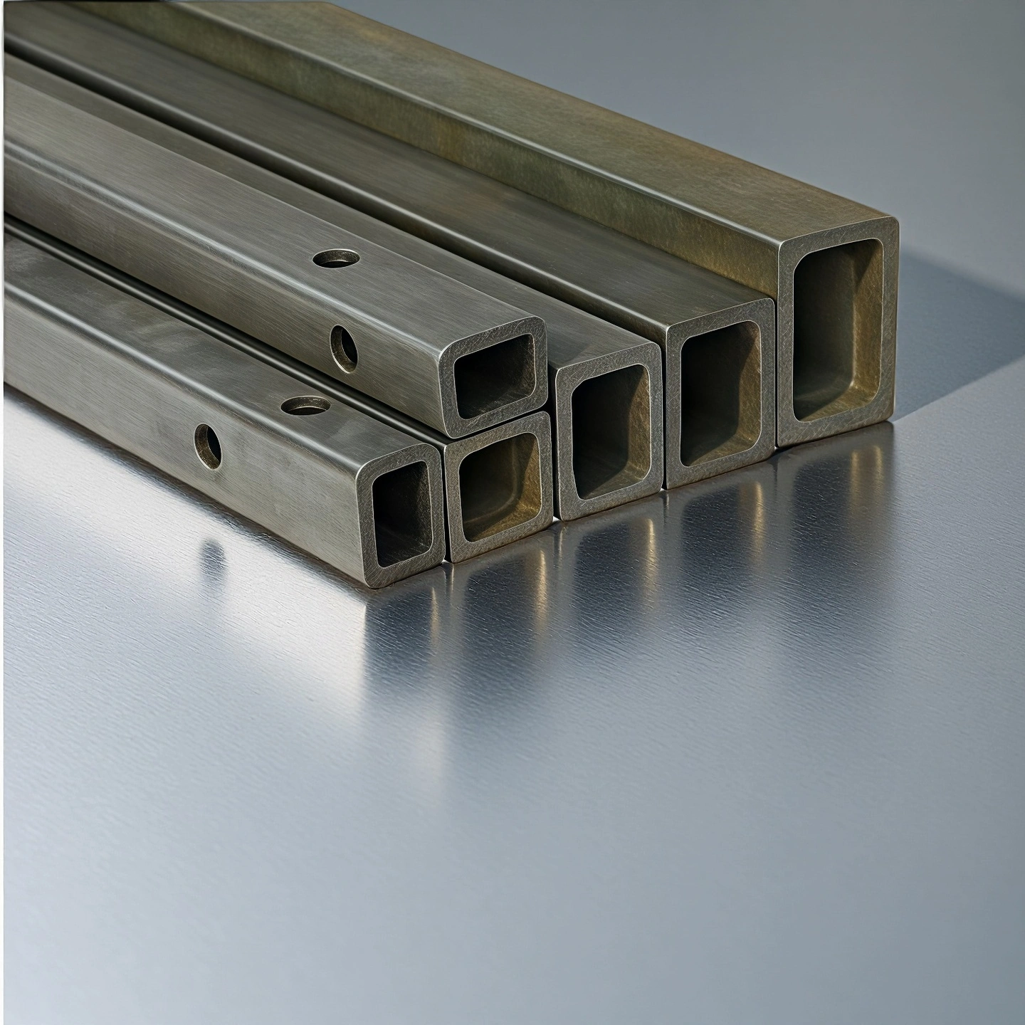
A nitride bonded silicon carbide beam is a high-temperature ceramic support beam made from silicon carbide particles bonded with silicon nitride. It is commonly used in ceramic kilns, shuttle kilns, tunnel kilns and furnace systems where the support structure must resist heat, thermal cycling, oxidation and mechanical loading. Compared with many conventional refractory supports, NBSiC beams provide a strong balance between high-temperature stability, load support and custom size flexibility.
Why Use NBSiC Beams for Kiln and Furnace Support?
1. Stable Support in High-Temperature Kilns
NBSiC beams are selected when kiln shelves, setter plates, refractory loads or furnace components require stable support during repeated heating and cooling cycles. The material system helps reduce deformation risk compared with weaker support materials in demanding thermal environments.
2. Thermal Shock Resistance for Repeated Firing Cycles
Kiln support beams often fail because of rapid temperature changes, uneven heating or poor support alignment. Nitride bonded silicon carbide provides better thermal shock resistance than many traditional refractory materials, which makes it suitable for ceramic firing, sintering and thermal processing systems.
3. Good Load-Bearing Capability with Reduced Beam Size
Because NBSiC has strong mechanical properties at elevated temperatures, the beam can often support furnace furniture or product loads with a more efficient cross-section. Final beam size should be reviewed according to span length, load distribution, support points and operating temperature.
4. Oxidation and Corrosion Resistance
The silicon carbide and silicon nitride bonded structure provides useful resistance against oxidation and many aggressive furnace atmospheres. For molten metal, slag or chemically active environments, application details should be reviewed before material selection.
Technical Properties of Nitride Bonded Silicon Carbide Beam
Nitride bonded silicon carbide beams are selected for kiln and furnace support positions where thermal shock resistance, oxidation resistance, mechanical strength and dimensional stability are important. The following properties are reference values for material evaluation. Final suitability should be reviewed according to furnace atmosphere, load distribution, support span, exposure time and heating cycle.
| Property | Reference Value | What It Means for Kiln Design |
|---|---|---|
| Material System | SiC with Si₃N₄ bonding | This structure combines silicon carbide thermal stability with a nitride bonding phase for high-temperature support applications. |
| Maximum Operating Temperature | Up to 1500°C | Suitable for many ceramic firing, heat-treatment and refractory furnace support positions, depending on atmosphere and load. |
| Thermal Conductivity | 120–150 W/m·K at 1000°C | Helps transfer heat across the beam and reduce local heat concentration in furnace furniture systems. |
| Flexural Strength | ≥ 300 MPa | Supports beam span design and load-bearing evaluation under thermal and mechanical stress. |
| Density | 3.10–3.20 g/cm³ | Indicates a dense ceramic structure for structural kiln furniture applications. |
| Vickers Hardness | ≥ 2500 HV | Supports wear resistance during repeated loading, sliding or contact with setter plates. |
| Elastic Modulus | ≥ 400 GPa | Helps maintain rigidity under mechanical load, but support design must still avoid point loading. |
| Thermal Expansion Coefficient | 3.0 × 10⁻⁶ /°C | Lower expansion helps reduce thermal stress during heating and cooling cycles. |
| Oxidation Resistance | High | Important for long firing cycles and oxygen-containing furnace atmospheres. |
| Chemical Resistance | High | Useful in many harsh furnace environments, but exact suitability depends on slag, vapor and atmosphere chemistry. |
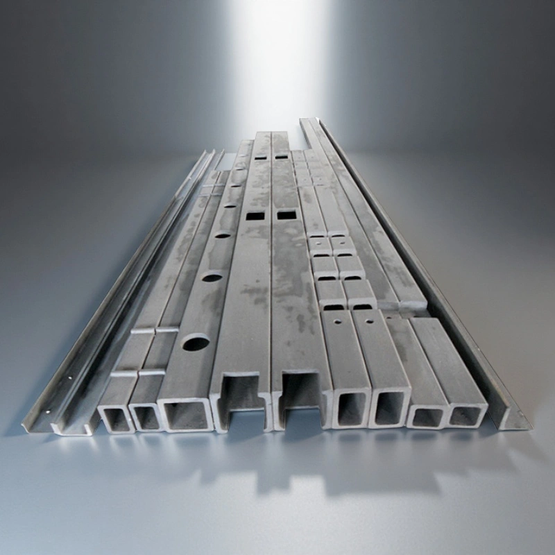
Standard and Custom NBSiC Beam Size Options
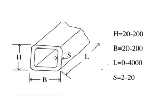
The following NBSiC beam sizes are reference options for kiln and furnace support design. The final beam selection should be reviewed according to span length, working temperature, load weight, support position, furnace atmosphere and installation method. Custom lengths, cross-sections and half-open structures can be reviewed from drawings or application requirements.
| NBSIC Beam | ||||
| Item No. | H(mm) | B(mm) | S(mm) | L(mm) |
| AT-NBSIC-FL001 | 20 | 20 | 4 | 50-4500mm |
| AT-NBSIC-FL002 | 20 | 20 | 5 | 50-4500mm |
| AT-NBSIC-FL003 | 20 | 30 | 4 | 50-4500mm |
| AT-NBSIC-FL004 | 20 | 30 | 5 | 50-4500mm |
| AT-NBSIC-FL005 | 20 | 40 | 5 | 50-4500mm |
| AT-NBSIC-FL006 | 25 | 30 | 5 | 50-4500mm |
| AT-NBSIC-FL007 | 30 | 30 | 4 | 50-4500mm |
| AT-NBSIC-FL008 | 30 | 30 | 5 | 50-4500mm |
| AT-NBSIC-FL009 | 30 | 40 | 4 | 50-4500mm |
| AT-NBSIC-FL010 | 30 | 40 | 5 | 50-4500mm |
| AT-NBSIC-FL011 | 30 | 40 | 6 | 50-4500mm |
| AT-NBSIC-FL012 | 30 | 50 | 4 | 50-4500mm |
| AT-NBSIC-FL013 | 30 | 50 | 5 | 50-4500mm |
| AT-NBSIC-FL014 | 30 | 50 | 6 | 50-4500mm |
| AT-NBSIC-FL015 | 30 | 60 | 5 | 50-4500mm |
| AT-NBSIC-FL016 | 30 | 60 | 6 | 50-4500mm |
| AT-NBSIC-FL017 | 45 | 50 | 4 | 50-4500mm |
| AT-NBSIC-FL018 | 45 | 50 | 5 | 50-4500mm |
| AT-NBSIC-FL019 | 45 | 50 | 6 | 50-4500mm |
| AT-NBSIC-FL020 | 40 | 40 | 5 | 50-4500mm |
| AT-NBSIC-FL021 | 40 | 40 | 6 | 50-4500mm |
| AT-NBSIC-FL022 | 40 | 40 | 7 | 50-4500mm |
| AT-NBSIC-FL023 | 40 | 50 | 6 | 50-4500mm |
| AT-NBSIC-FL024 | 40 | 50 | 7 | 50-4500mm |
| AT-NBSIC-FL025 | 40 | 60 | 5 | 50-4500mm |
| AT-NBSIC-FL026 | 40 | 60 | 6 | 50-4500mm |
| AT-NBSIC-FL027 | 40 | 60 | 7 | 50-4500mm |
| AT-NBSIC-FL028 | 45 | 45 | 5 | 50-4500mm |
| AT-NBSIC-FL029 | 45 | 45 | 6 | 50-4500mm |
| AT-NBSIC-FL030 | 45 | 45 | 7 | 50-4500mm |
| AT-NBSIC-FL031 | 50 | 50 | 5 | 50-4500mm |
| AT-NBSIC-FL032 | 50 | 50 | 6 | 50-4500mm |
| AT-NBSIC-FL033 | 50 | 50 | 7 | 50-4500mm |
| AT-NBSIC-FL034 | 50 | 60 | 6 | 50-4500mm |
| AT-NBSIC-FL035 | 50 | 60 | 7 | 50-4500mm |
| AT-NBSIC-FL036 | 50 | 60 | 8 | 50-4500mm |
| AT-NBSIC-FL037 | 50 | 70 | 6 | 50-4500mm |
| AT-NBSIC-FL038 | 50 | 70 | 7 | 50-4500mm |
| AT-NBSIC-FL039 | 50 | 70 | 8 | 50-4500mm |
| AT-NBSIC-FL040 | 60 | 60 | 6 | 50-4500mm |
| AT-NBSIC-FL041 | 60 | 60 | 7 | 50-4500mm |
| AT-NBSIC-FL042 | 60 | 60 | 8 | 50-4500mm |
| AT-NBSIC-FL043 | 60 | 60 | 9 | 50-4500mm |
| AT-NBSIC-FL044 | 60 | 70 | 7 | 50-4500mm |
| AT-NBSIC-FL045 | 60 | 70 | 8 | 50-4500mm |
| AT-NBSIC-FL046 | 60 | 70 | 9 | 50-4500mm |
| AT-NBSIC-FL047 | 60 | 80 | 7 | 50-4500mm |
| AT-NBSIC-FL048 | 60 | 80 | 8 | 50-4500mm |
| AT-NBSIC-FL049 | 60 | 80 | 9 | 50-4500mm |
| AT-NBSIC-FL050 | 60 | 90 | 7 | 50-4500mm |
| AT-NBSIC-FL051 | 60 | 90 | 8 | 50-4500mm |
| AT-NBSIC-FL052 | 60 | 90 | 9 | 50-4500mm |
| AT-NBSIC-FL053 | 70 | 70 | 7 | 50-4500mm |
| AT-NBSIC-FL054 | 70 | 70 | 8 | 50-4500mm |
| AT-NBSIC-FL055 | 70 | 70 | 9 | 50-4500mm |
| NBSIC Beam Half-Opened | ||||
| Item No. | H(mm) | B(mm) | S(mm) | L(mm) |
| AT-NBSIC-FL056 | 50 | 20 | 5 | 50-4500mm |
| AT-NBSIC-FL057 | 50 | 20 | 6 | 50-4500mm |
| AT-NBSIC-FL058 | 50 | 20 | 7 | 50-4500mm |
| AT-NBSIC-FL059 | 50 | 20 | 8 | 50-4500mm |
| AT-NBSIC-FL060 | 60 | 25 | 6 | 50-4500mm |
| AT-NBSIC-FL061 | 60 | 25 | 7 | 50-4500mm |
| AT-NBSIC-FL062 | 60 | 25 | 8 | 50-4500mm |
| AT-NBSIC-FL063 | 60 | 25 | 9 | 50-4500mm |
| AT-NBSIC-FL064 | 70 | 30 | 7 | 50-4500mm |
| AT-NBSIC-FL065 | 70 | 30 | 8 | 50-4500mm |
| AT-NBSIC-FL066 | 70 | 30 | 9 | 50-4500mm |
How to Select the Right Nitride Bonded SiC Beam
| Selection Factor | Why It Matters | Information to Provide |
|---|---|---|
| Beam Span | Longer span increases bending stress. | Distance between support points. |
| Load Weight | Load affects cross-section and safety margin. | Total supported weight and load distribution. |
| Furnace Temperature | Temperature affects material strength and oxidation behavior. | Working temperature and peak temperature. |
| Heating Cycle | Rapid cycling may increase thermal shock risk. | Heating rate, cooling rate and cycle frequency. |
| Atmosphere | Oxidizing, reducing or corrosive atmospheres affect material choice. | Air, inert gas, reducing gas, vapor, slag or metal contact. |
| Contact Surface | Point loading can cause local stress. | Shelf shape, plate contact area and support method. |
| Installation Space | Existing furnace structure limits beam size. | Drawing, old beam photo or furnace layout. |
Packaging for Nitride Bonded Silicon Carbide Beams
The Nitride Bonded Silicon Carbide Beam is carefully packaged to ensure safe transportation and handling. Each beam is securely wrapped and placed in protective crates, with adequate padding to prevent any damage during transit. The packaging is designed to protect the beam from external shocks, ensuring it arrives in excellent condition for use in high-temperature applications.