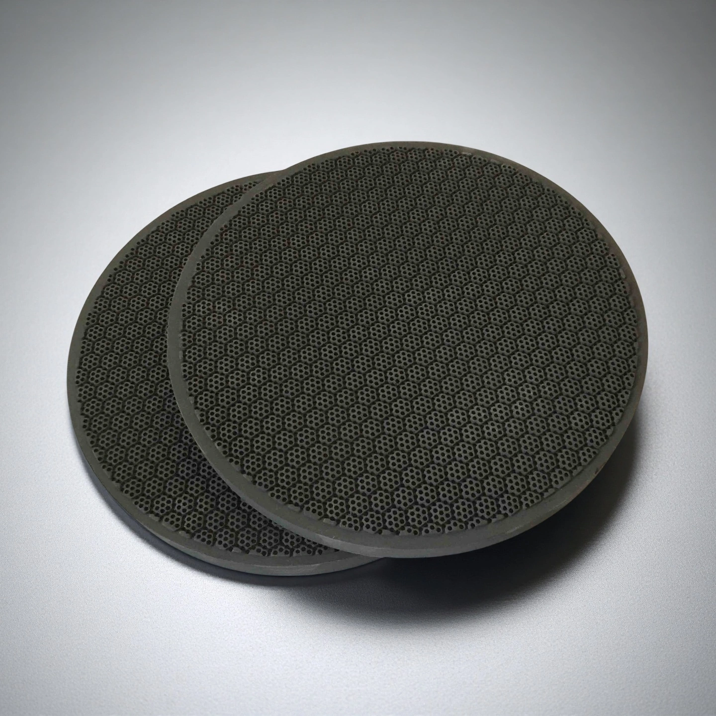
ADCERAX® Silicon Carbide Honeycomb Ceramic is engineered for industrial environments that require stable filtration, thermal storage, and catalytic support under continuous high-temperature and corrosive operating conditions. Its interconnected porous structure and high thermal conductivity enable uniform gas flow and reliable performance during thermal cycling, supporting the operational needs of diesel emission systems, RTO units, and chemical processing equipment. These characteristics allow engineering teams to maintain consistent system efficiency while extending service intervals in demanding industrial applications.
High-Performance Characteristics of Silicon Carbide Honeycomb Ceramic
-
Microstructure Optimized for High-Temperature Operation
Short-term exposure performance reaches ≥1650 °C, enabling safe operation during system startups or abnormal temperature spikes. These characteristics reduce failure risk in diesel particulate systems and RTO ceramic beds.
-
High Cell Density for Controlled Flow Distribution
Honeycomb channels are available in 100–300 CPSI, providing selectable flow resistance for different industrial processes. This range allows engineers to balance filtration efficiency with pressure-drop limits in emission systems.
-
Mechanical Strength Maintained Under Thermal Cycling
The ceramic demonstrates resistance to microcrack propagation after 1000 cycles (20 °C → 900 °C), indicating strong survival under repeated heating and cooling. This ensures reliable use in continuously operated filtration modules.
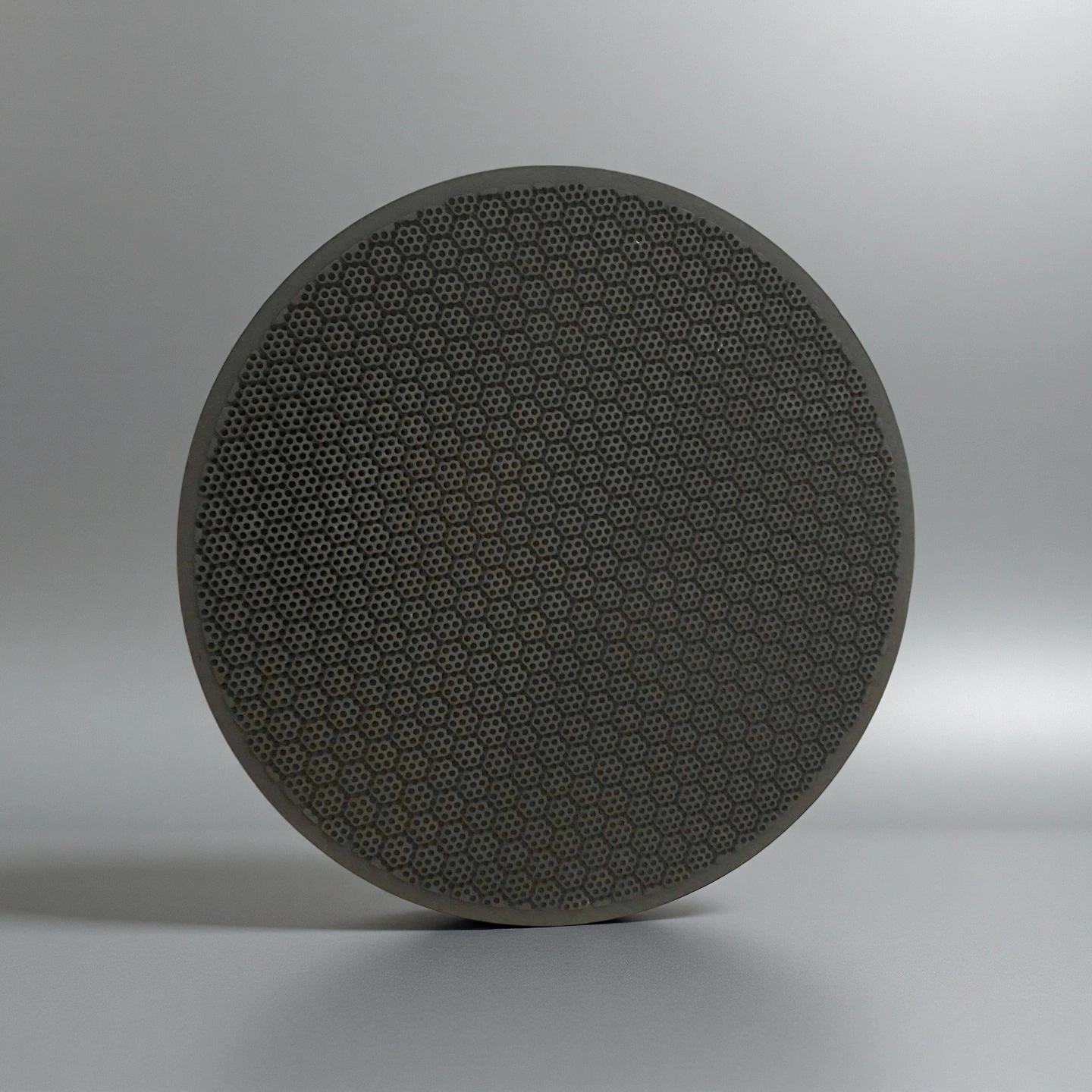
- High Specific Surface Area for Catalytic Coating Efficiency
The honeycomb geometry increases available surface area by 25–40% compared with non-structured SiC blocks, enabling higher catalytic loading efficiency. This structure enhances fuel oxidation or particulate conversion reactions.
Technical Specifications of Silicon Carbide Honeycomb Ceramic
ADCERAX® Silicon Carbide Honeycomb Ceramic demonstrates a distinctive combination of thermal resilience, mechanical reliability, and structural uniformity that supports high-demand industrial processes. Its engineered microstructure enables stable functionality under extreme heat cycles while maintaining consistent flow characteristics.
| Property |
Specification |
| Chemical Composition (SiC) |
≥ 99% |
| Density |
2.65–2.75 g/cm³ |
| Open Porosity |
38–42% |
| Thermal Conductivity |
25–35 W/m·K at 25 °C |
| Maximum Operating Temperature |
1350–1500 °C (oxidizing atmosphere) |
| Thermal Expansion Coefficient |
4.2–4.8 ×10⁻⁶ /K (25–800 °C) |
| Flexural Strength |
38–45 MPa |
| Compressive Strength |
180–220 MPa |
| Acid Resistance |
Mass loss ≤ 0.5% after acid immersion |
| Alkali Resistance |
Mass loss ≤ 1.0% after alkali immersion |
| Air Permeability |
5–8 m³/h·m² at fixed pressure drop |
| Specific Heat Capacity |
0.75–0.85 kJ/kg·K |
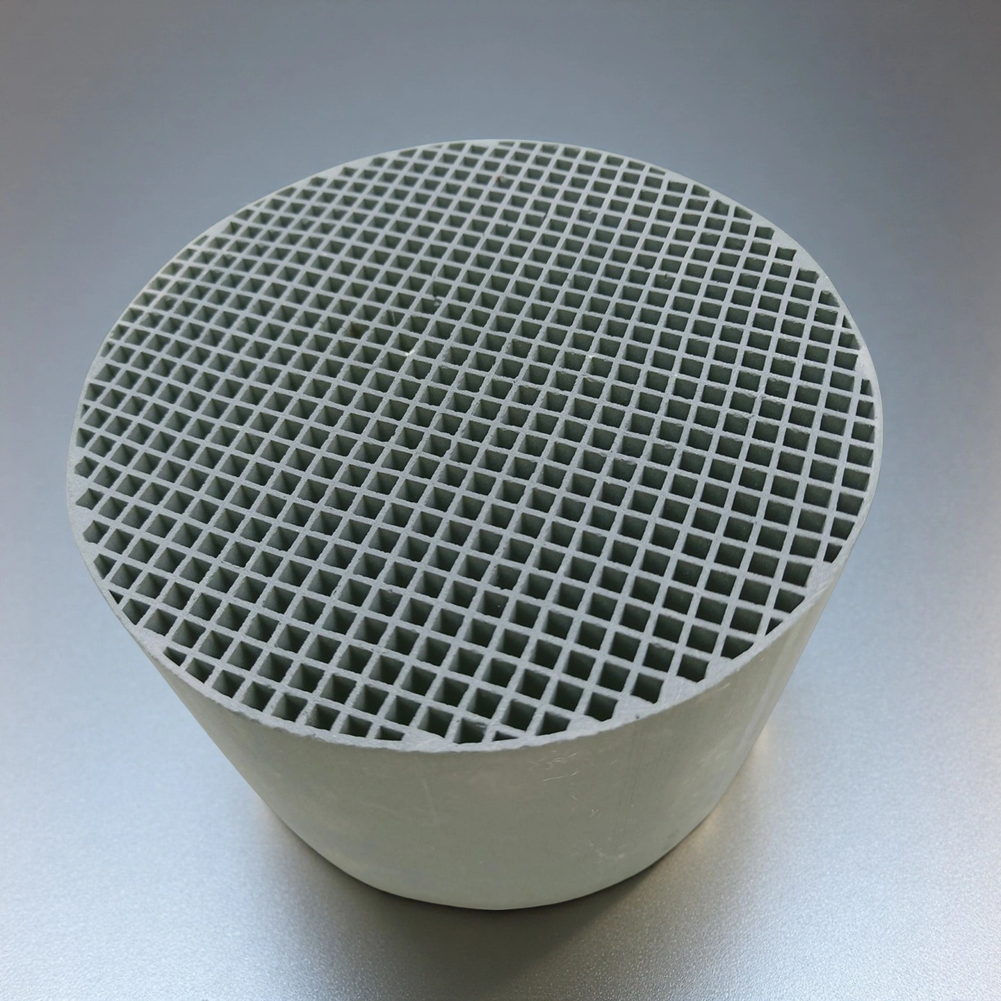
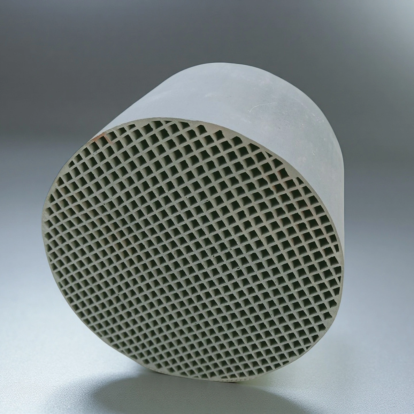
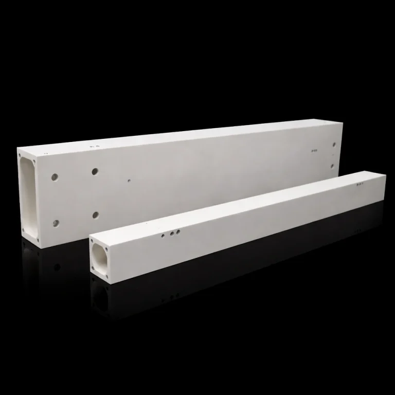
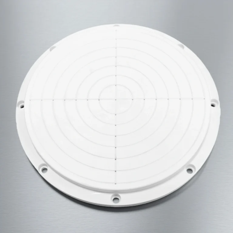
Dimensions of Silicon Carbide Honeycomb Ceramic
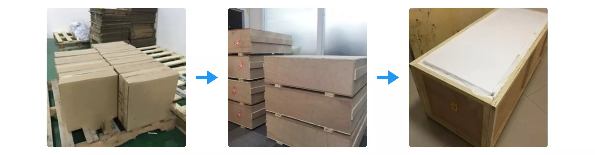
Protective Packaging for Silicon Carbide Honeycomb Ceramic
Silicon Carbide Honeycomb Ceramic is packed using a multi-layer protection process that begins with reinforced cartons placed on treated pallets to prevent vibration damage. Each unit is then secured inside strengthened plywood cases that maintain stability during long-distance transport. The final outer crate provides added compression resistance, ensuring the ceramics arrive intact for demanding industrial applications.
ADCERAX® Silicon Carbide Honeycomb Ceramic Overcomes Critical Process Challenges in Modern Industrial Systems
Industries operating under extreme thermal loads, corrosive atmospheres, and high-throughput flow conditions increasingly turn to ADCERAX® Silicon Carbide Honeycomb Ceramic to resolve long-standing reliability bottlenecks. Its engineered honeycomb geometry delivers stable mass-transfer efficiency, predictable thermal behavior, and long-cycle durability that conventional ceramics cannot sustain.
-
High-Temperature Combustion Chambers for Continuous Industrial Firing Lines
✅Key Advantages
1. Thermal Shock Resistance
ADCERAX® Silicon Carbide Honeycomb Ceramic withstands rapid heating and cooling cycles without cracking, maintaining geometric integrity at temperatures up to 1600°C. This stability ensures consistent heat distribution across continuous firing lines.
2. High Thermal Conductivity
With thermal conductivity exceeding 120 W/m·K, the honeycomb structure evenly diffuses heat, reducing hot spots and ensuring uniform firing curves. This prevents localized overheating and product quality defects.
3. Dimensional Stability under Load
The rigid honeycomb architecture sustains mechanical strength above 35 MPa under continuous thermal stress. It supports heavy industrial burners without warping or deformation, enabling long-term operational reliability.
✅ ️Problem Solved
In a European ceramic tile facility, traditional refractories developed microcracks after repeated firing cycles, causing uneven tile coloring and frequent line stoppages. After replacing these with ADCERAX® Silicon Carbide Honeycomb Ceramic, the plant achieved a 12% improvement in process consistency and eliminated unplanned downtime, maintaining uniform thermal profiles across a 100-meter continuous firing tunnel. The honeycomb’s resistance to thermal fatigue directly stabilized firing curves over months of continuous operation.
-
Catalyst Support Structures in High-Load De-NOx and VOC Treatment Reactors
✅Key Advantages
1. Chemical Corrosion Resistance
ADCERAX® Silicon Carbide Honeycomb Ceramic resists degradation from flue gas components like SOx and NOx, retaining surface integrity for over 20,000 operating hours. This preserves catalyst adhesion and efficiency under aggressive chemical exposure.
2. High Mechanical Strength
With compressive strength above 40 MPa, the ceramic supports heavy catalyst layers without fracture or deformation, even under high gas throughput. This ensures stable flow channels and uniform contact with reactive gases.
3. Enhanced Flow Distribution
The engineered cell structure maintains flow uniformity above 95%, minimizing channeling and pressure drop. This uniformity enhances catalytic conversion efficiency and prolongs reactor service life.
✅ ️Problem Solved
A North American power plant using conventional ceramic substrates suffered catalyst layer detachment and uneven NOx removal, leading to a 15% drop in conversion efficiency during peak operation. After installing ADCERAX® Silicon Carbide Honeycomb Ceramic supports, the facility maintained consistent catalytic activity over 18 months, reducing maintenance interventions and stabilizing emission levels in compliance with environmental regulations.
-
Harsh-Environment Gas Filtration and Heat Recovery Systems in Metallurgical Processing
✅Key Advantages
1. Erosion Resistance
ADCERAX® Silicon Carbide Honeycomb Ceramic withstands abrasive particulate impact with hardness above 2200 HV, maintaining pore integrity under high-velocity gas streams. This reduces filter media wear and prolongs operational cycles.
2. Thermal Fatigue Durability
The honeycomb design endures repeated temperature fluctuations without cracking, operating reliably at temperatures up to 1400°C. This ensures continuous filtration and stable heat recovery efficiency.
3. Stable Gas Permeability
Engineered cell channels maintain permeability above 90%, preventing clogging and sustaining consistent airflow. This stability is critical for uninterrupted metallurgical gas cleaning processes.
✅ ️Problem Solved
A steel mill previously faced frequent filter blockages and erosion-related shutdowns, reducing production efficiency and heat recovery rates. By implementing ADCERAX® Silicon Carbide Honeycomb Ceramic, the plant achieved over 20% longer filter service life and uninterrupted high-cycle operation, maintaining stable airflow and consistent particulate removal while withstanding abrasive, high-temperature gas streams.
Operational Guidance for ADCERAX® Silicon Carbide Honeycomb Ceramic in Industrial Systems
Silicon Carbide Honeycomb Ceramic requires correct handling, installation, and maintenance to ensure stable performance under demanding thermal and chemical environments. ADCERAX® provides a structured operational guide to help engineering teams reduce avoidable risks, extend service intervals, and maintain consistent system output across continuous industrial processes.
-
Handling and Pre-Installation Requirements
1. Avoid mechanical shock during transportation and unpacking, as impact forces can introduce micro-defects that evolve under thermal cycling. Users should keep the modules supported from the base and prevent side pressure during movement. Stable handling reduces the probability of early structural fatigue in continuous-temperature applications.
2. Maintain a clean staging area before installation, ensuring no abrasive particles enter the channels. Foreign material can interfere with gas distribution and diminish operational uniformity. Proper preparation preserves the material’s designed flow architecture.
3. Verify compatibility with system thermal profiles, especially in long-duration heating operations. Engineering teams should cross-check maximum continuous temperatures and thermal ramps. Confirming alignment prevents material stress accumulation during operation.
-
Installation in Filtration, Thermal Storage, and Catalytic Units
1. Ensure uniform axial alignment when placing modules, preventing uneven stress accumulation during expansion and contraction. Misalignment can disturb gas flow and reduce system stability. Controlled placement supports long-term dimensional integrity.
2. Use stable support frames and non-reactive gaskets, ensuring no metal components introduce chemical contamination during operation. Material compatibility reduces the risk of reaction-induced degradation. This practice maintains consistent surface conditions for filtration or catalysis.
3. Confirm sealing integrity after installation, especially for systems relying on precise flow management. Any bypass flow reduces efficiency and accelerates loading on downstream components. Proper sealing ensures predictable thermal and gas-flow performance.
-
Routine Operation and System Monitoring
1. Monitor differential pressure trends during operation, as gradual increases indicate particulate accumulation. Early detection helps avoid unnecessary strain on the material. Predictive monitoring supports longer service intervals in continuous-flow systems.
2. Track thermal cycling frequency and amplitude, particularly in units where temperature transitions occur rapidly. Excessive cycling can affect long-term microstructural stability. Following defined temperature profiles ensures sustainable performance.
3. Maintain stable upstream process conditions, including gas composition and particulate load. Sudden variations impose stress on the ceramic substrate. Consistent process conditions enhance operational reliability.
-
Cleaning, Maintenance, and Storage Recommendations
1. Perform scheduled cleaning using non-abrasive methods, ensuring that deposited particulates are removed without altering channel geometry. Harsh tools or blasting methods should be avoided to prevent pore distortion. Gentle procedures preserve functional surface area.
2. Replace damaged modules promptly, especially if cracks or erosion marks appear during inspection. Continued use of compromised units can lead to uneven flow distribution. Immediate replacement protects overall system efficiency.
3. Store unused modules in a controlled, low-humidity environment, keeping them inside their protective crates until installation. Moisture exposure may affect surface conditions during long-term storage. Proper storage safeguards material integrity before deployment.