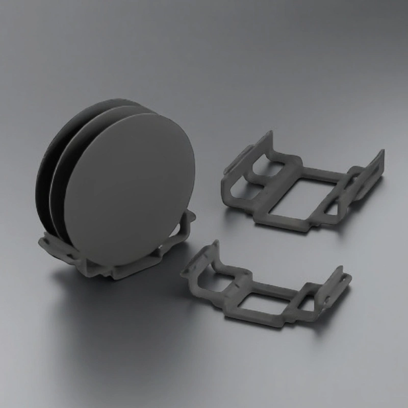
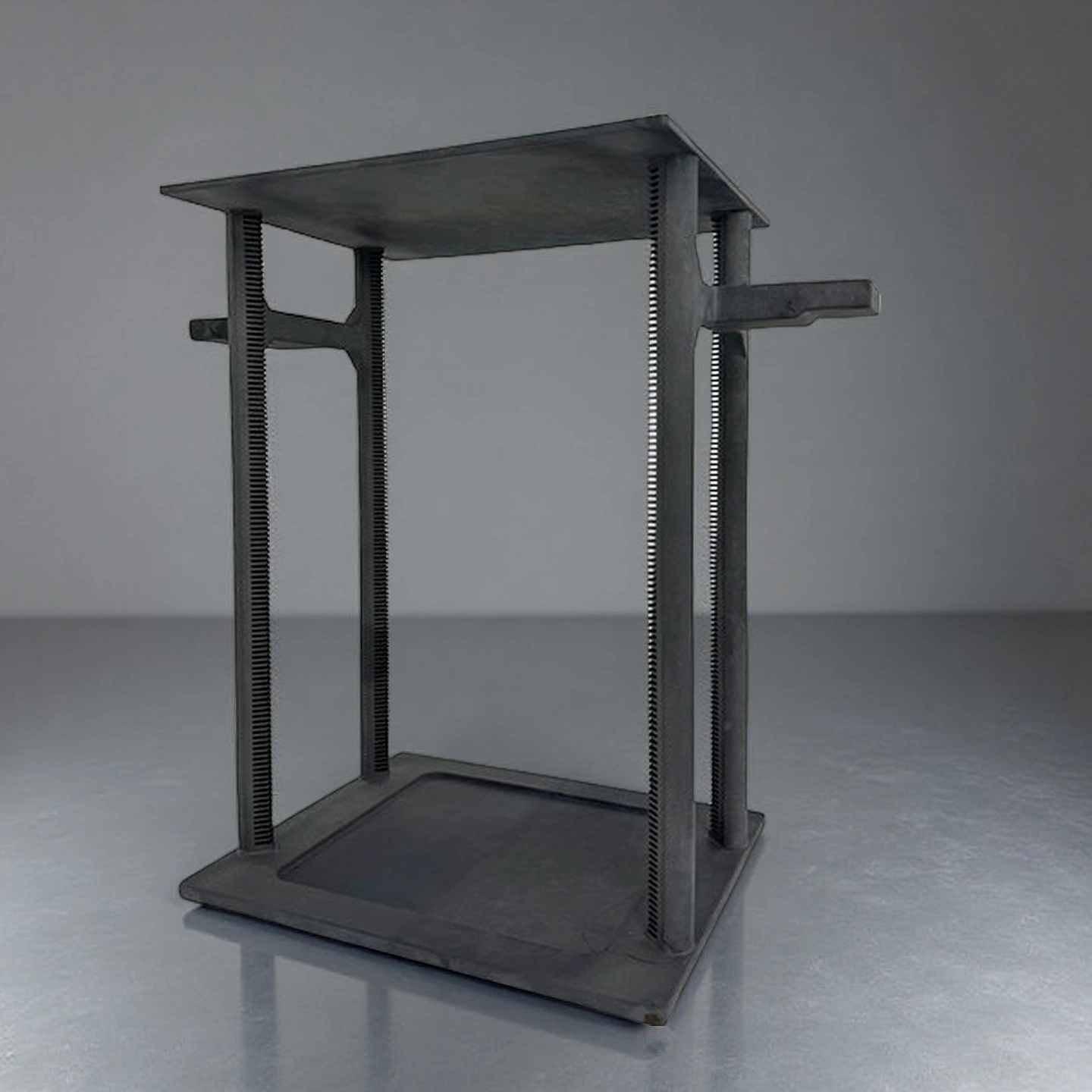
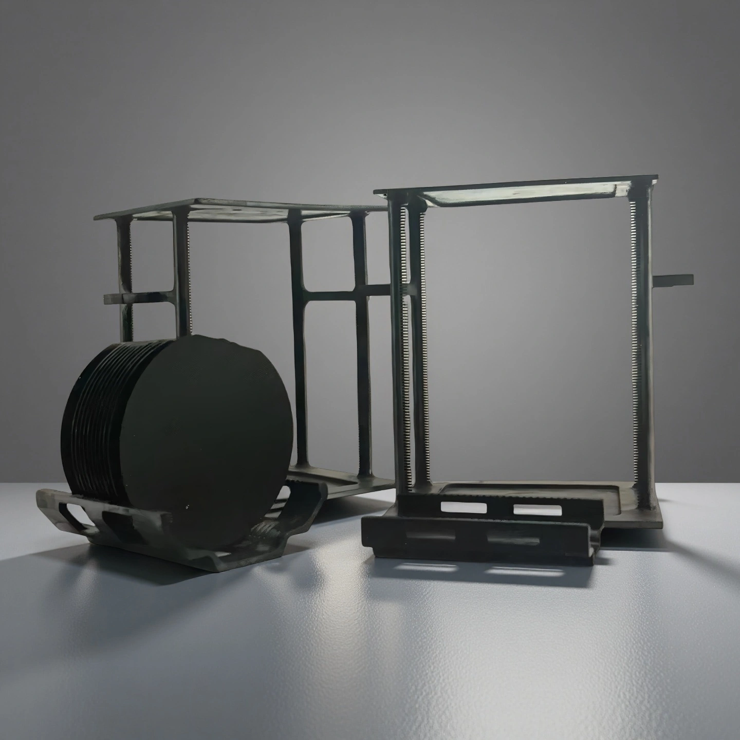
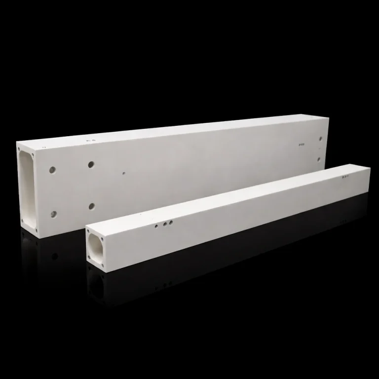
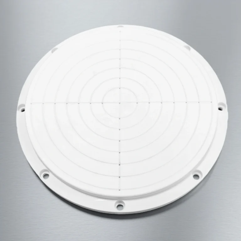
ADCERAX® Silicon Carbide Wafer Boat supports wafer handling and high-temperature processing in diffusion, oxidation and annealing furnace environments where stable geometry and thermal consistency are critical. Its SiC structure maintains mechanical rigidity and predictable behavior across extended heating cycles, allowing controlled wafer positioning and reliable gas-flow interaction throughout the process chamber. This performance makes the SiC Wafer Carrier Boat suitable for equipment builders and furnace system integrators seeking dependable loading stability and long operating life under demanding thermal conditions.
Precision Material and Thermal Performance Features of the Silicon Carbide Wafer Boat
-
High-Temperature Stability Across Continuous Furnace Cycles
The structure maintains shape under 1400–1500°C thermal exposure, allowing the sintered sic wafer boat to remain dimensionally stable through extended heat cycles.
Its low thermal expansion of 4.0–4.5×10⁻⁶/K supports uniform wafer spacing during long oxidation or diffusion runs without drift.
High flexural strength of 350–430 MPa ensures the carrier endures repeated loading sequences without deformation accumulation.
-
Controlled Surface and Slot Geometry for Consistent Wafer Alignment
Surface roughness of Ra 0.2–0.6 μm minimizes friction and reduces particle generation during loading and unloading.
Slot pitch stability within ±0.05–0.10 mm supports accurate wafer placement and repeatable gas-flow interaction during furnace processing.
Straightness maintained at ≤0.05 mm / 100 mm ensures predictable wafer support over the full carrier length.
-
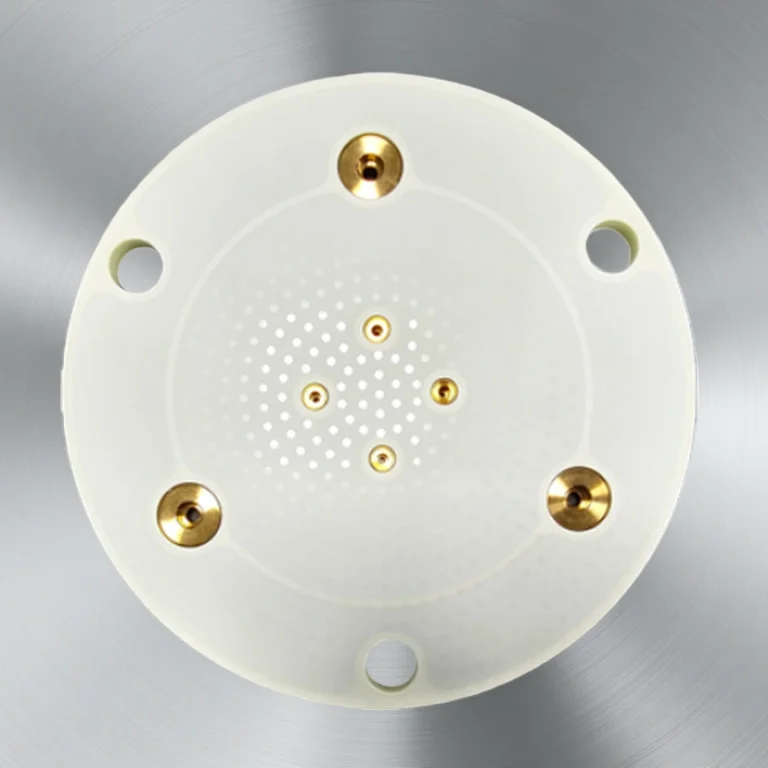
Chemical and Atmospheric Compatibility for Furnace Process Requirements
The high purity sic wafer boat remains chemically inert in H₂, N₂, Ar, NH₃, Cl₂, HCl, and SiH₄ atmospheres, supporting clean thermal environments.
Oxidation resistance validated in O₂-based cycles enables stable performance in dry and wet oxidation steps without surface degradation.
Low porosity at <0.1–0.5% reduces absorption and prevents micro-crack development during repeated heating and cooling sequences.
Technical Specifications of Silicon Carbide Wafer Boat
ADCERAX® Silicon Carbide Wafer Boat is defined by its stable high-temperature behavior, controlled microstructure, and repeatable material performance that support demanding diffusion, oxidation, and annealing furnace environments.
| Property |
Specification |
| Material System |
RBSiC / SSiC high-density silicon carbide |
| Bulk Density |
3.05–3.17 g/cm³ |
| Open Porosity |
<0.5% (RBSiC) / <0.1% (SSiC) |
| Flexural Strength |
220–290 MPa (RBSiC) / 350–430 MPa (SSiC) |
| Compressive Strength |
>2200 MPa |
| Thermal Conductivity |
80–120 W/m·K |
| Thermal Expansion |
4.0–4.5×10⁻⁶/K (RT–1000°C) |
| Maximum Service Temperature |
1450–1600°C depending on grade |
| Chemical Compatibility |
Stable in H₂, N₂, Ar, NH₃, NH₃, Cl₂, HCl, SiH₄ atmospheres |
| Oxidation Resistance |
Maintains integrity in O₂-based furnace cycles |
| Surface Roughness |
Ra 0.2–0.6 μm |
Dimensions of Silicon Carbide Wafer Boat
|
Silicon Carbide Wafer Boat |
|
Item No. |
Diameter(mm) |
Height (mm) |
|
AT-SIC-T1001 |
Customize |
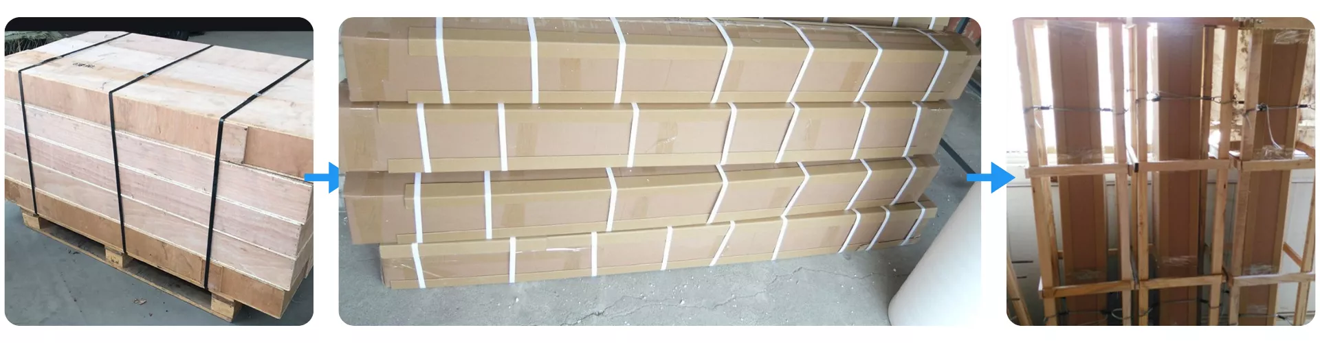
Packaging and Shipment Protection for Silicon Carbide Wafer Boat
Silicon Carbide Wafer Boat units are packed in reinforced multi-layer cartons with internal cushioning to prevent vibration and contact damage during transport. Each carton is further secured with strapping and stacked within a protective wooden frame to stabilize the load throughout long-distance handling. The finished pallets are prepared for international shipping, ensuring safe arrival under standard sea or air-freight conditions.
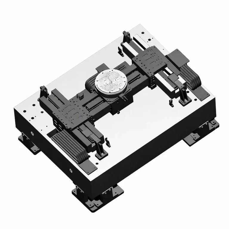
ADCERAX® Silicon Carbide Wafer Boat Solves Critical Challenges in Photovoltaic Thermal Processing
The Silicon Carbide Wafer Boat enables stable wafer handling, uniform gas–solid interaction, and predictable thermal behavior across high-temperature steps in photovoltaic cell manufacturing, where diffusion, oxidation, and high-throughput annealing demand consistent carrier performance.
-
Silicon Carbide Wafer Boat in Solar Cell Phosphorus Diffusion Furnaces
✅Key Advantages
1. Stable Slot Geometry Under Long Diffusion Cycles
The carrier maintains slot spacing stability within ±0.05–0.10 mm after repeated high-temperature diffusion runs. This control keeps wafer-to-wafer distance variation typically below 2–3% across a full stack, supporting tighter sheet-resistance distribution.
2. Reduced Deformation in Extended High-Temperature Exposure
Flexural strength in the range of 350–430 MPa and low creep behavior limit long-term bowing of the boat body. Even after several hundred diffusion cycles, measured deflection can remain below 0.1 mm along the loaded span, preventing gradual drift in gas-flow channels.
3. Consistent Thermal Response for Large-Batch Processing
Thermal conductivity of 80–120 W/m·K supports balanced heat transfer along the carrier, reducing temperature gradients in dense wafer loads. This contributes to sheet-resistance variation reductions where across-batch non-uniformity can be lowered by 10–20% compared with less conductive materials.
✅ ️Problem Solved
A photovoltaic producer operating multi-lane phosphorus diffusion furnaces observed rising sheet-resistance scatter linked to carrier distortion after intensive use. Measurements showed progressive slot opening changes and local bowing that correlated with higher resistance deviation between wafers positioned at the center and edges of the load. After switching to ADCERAX® Silicon Carbide Wafer Boat units, flatness and slot stability remained within controlled limits through extended cycles, and gas-flow distribution across the furnace tube became more repeatable. Over several production campaigns, process data indicated a reduction in sheet-resistance spread on full batches by approximately 15–18%, allowing the line to run with fewer recipe compensations and less reclassification of borderline cells.
-
Silicon Carbide Wafer Boat in Solar Cell Annealing and Surface Passivation Lines
✅Key Advantages
1. High Resistance to Rapid Thermal Cycling
The carrier structure sustains temperature jumps in the range of 300–400°C per cycle without measurable crack propagation in standard inspection. After several hundred annealing cycles, mechanical integrity testing can still show flexural strength maintained above 90% of initial values, which supports stable wafer handling.
2. Controlled Transfer of Mechanical Stress to Wafers
Low thermal expansion of 4.0–4.5×10⁻⁶/K limits mismatch stresses that would otherwise transfer to thin PV wafers during fast ramps. In practice, bow measurements on wafers processed with the Silicon Carbide Wafer Boat have shown curvature variation reductions of 10–15% compared with carriers using higher-expansion materials.
3. Low-Porosity Body for Clean Annealing Environment
Open porosity of <0.1–0.5% reduces gas entrapment and minimizes particle release during hydrogen or nitrogen annealing. This helps keep particle counts on wafer surfaces at levels compatible with stable passivation performance, with observed surface defect counts lowered by 10–20% in comparative line checks.
✅ ️Problem Solved
A PV line running hydrogen annealing and surface passivation reported drift in wafer bow and local defects that appeared after multiple fast-ramp cycles. Conventional carriers developed micro-cracks and localized distortion, which gradually introduced stress patterns that could be tracked into passivation performance scatter. After adopting ADCERAX® Silicon Carbide Wafer Boat carriers, thermal cycling tests showed stable carrier geometry and lower transfer of mechanical stress into the wafer stack. Subsequent process monitoring indicated more consistent wafer curvature at the anneal exit and a measurable decrease in passivation-related defect indicators, supporting tighter control of final cell performance.
-
Silicon Carbide Wafer Boat in Solar LPCVD Anti-Reflection Coating Processes
✅Key Advantages
1. Controlled Slot Pitch for Film Thickness Uniformity
Slot positioning held within ±0.05–0.10 mm supports predictable spacing in the wafer stack across the full carrier length. This stability helps maintain film thickness variation within target limits, where coating non-uniformity on production lots can be reduced by 10–15% compared with carriers showing larger geometric drift.
2. Thermal Conductivity Supporting Uniform Deposition Conditions
With thermal conductivity in the 80–120 W/m·K range, the Silicon Carbide Wafer Boat distributes heat more evenly along the loaded wafers. This reduces localized hot or cool regions in the LPCVD tube, contributing to narrower thickness distribution bands and more consistent refractive index across the coated surface.
3. Chemically Robust Surface in Reactive LPCVD Atmospheres
The SiC material remains stable in SiH₄ / NH₃ and related process gases used for anti-reflection coatings. Surface stability and low roughness in the Ra 0.2–0.6 μm range minimize micro-particle generation during long coating campaigns, supporting cleaner film growth conditions.
✅ ️Problem Solved
A solar module manufacturer running LPCVD anti-reflection coatings identified recurring thickness gradients from top to bottom of the wafer stack, linked to inconsistent carrier geometry and thermal behavior. Analysis of historical data showed that lots processed after extended carrier use exhibited wider film-thickness spreads and increased variability in optical performance. After implementing ADCERAX® Silicon Carbide Wafer Boat carriers with controlled slot pitch and higher thermal conductivity, coating thickness profiles across batches became more compact, and the difference between wafers at the top and bottom positions was narrowed by around 12–16%. This improvement reduced the number of wafers falling outside the preferred coating window and supported more stable cell efficiency distribution along the line.
ADCERAX® Silicon Carbide Wafer Boat User Guide for Stable, Safe, and Consistent Furnace Operation
The Silicon Carbide Wafer Boat requires proper handling, loading discipline, and maintenance awareness to ensure consistent performance across diffusion, oxidation, annealing, and LPCVD cycles.
-
PWafer Loading Practices for Consistent Furnace Performance
1. Maintain controlled placement when loading wafers into the boat to protect slot geometry and prevent uneven distribution during thermal cycles. Each loading sequence should be performed with steady alignment to avoid lateral stress on the supporting walls and ensure stable wafer spacing throughout the run. Regular checks of slot surfaces help identify early signs of wear that could affect gas-flow uniformity.
2. Inspect the contact edges for debris before each loading cycle to maintain clean interface points and minimize micro-scratching on wafer surfaces. Light air-blowing or non-abrasive brushing prevents particle buildup that could transfer contamination into the process tube. Ensuring the carrier is clean at every cycle supports uniform thermal interaction.
3. Position the carrier on the furnace loading arm or track using the designated support zones to preserve structural balance under high-temperature movement. Off-center loading increases bending stress during transfer and may influence run-to-run repeatability in furnace conditions. Following stable placement practices improves reproducibility of wafer behavior across batches.
-
Pre-Furnace Inspection and Handling Recommendations
1. Perform a brief geometric check before each run to confirm flatness consistency and detect unusual changes from previous cycles. Any observed deviations should be evaluated promptly to avoid long-term drift during furnace exposure. These checks help maintain predictable wafer alignment.
2. Handle the boat using both support ends to limit torsional loading on the body, especially after repeated thermal cycling. Avoid applying direct pressure to the slot region to prevent micro-crack formation under local stress. Consistent handling reduces risk of structural fatigue.
3. Store the boat in a cushioned, upright position to maintain surface protection against accidental abrasion or impact during idle periods. Avoid stacking carriers without separation pads to prevent friction contact and surface damage. Controlled storage contributes to longer service life.
-
In-Process Operating Guidance for Thermal Stability
1. Allow the boat to enter and exit the furnace under controlled ramp rates appropriate for SiC stability to minimize shock loading. Abrupt transitions between heating and cooling increase fatigue, particularly in high-throughput PV lines. Maintaining moderate transitions supports more predictable cycle performance.
2. Confirm that furnace loading systems apply uniform mechanical support along the boat’s underside to prevent sagging during periods of maximum thermal load. Uneven support points can generate bending forces that impact wafer spacing. Balanced mechanical contact improves long-term dimensional consistency.
3. Monitor atmospheric conditions for stable chemical compatibility, ensuring gases such as H₂, O₂, N₂, NH₃ or SiH₄ remain within process boundaries to avoid localized surface reactions. Sudden changes in chemistry can affect surface conditions and reduce cleanliness of wafer contact zones. Consistent gas profiles help preserve surface integrity.
-
Maintenance, Cleaning, and Service-Life Management
1. Clean the boat using non-abrasive chemical agents compatible with SiC furnace environments, ensuring no residue remains that could transfer into diffusion, oxidation or LPCVD tubes. Rinse with DI water and dry fully before reuse to maintain low particle generation. Proper cleaning preserves slot condition and surface roughness.
2. Perform periodic dimensional checks using controlled measurement tools to verify slot spacing stability and structural straightness after cumulative cycles. Early identification of drift helps operators prevent process deviations or wafer stack misalignment. Routine inspection supports long-term uniformity of furnace runs.
3. Replace carriers once thermal-cycle thresholds or visible surface degradation indicate reduced structural capability, preventing impact on wafer curvature, coating uniformity, or doping profiles. Tracking life-cycle data supports predictive maintenance planning. Consistent renewal practices improve overall line stability.