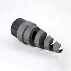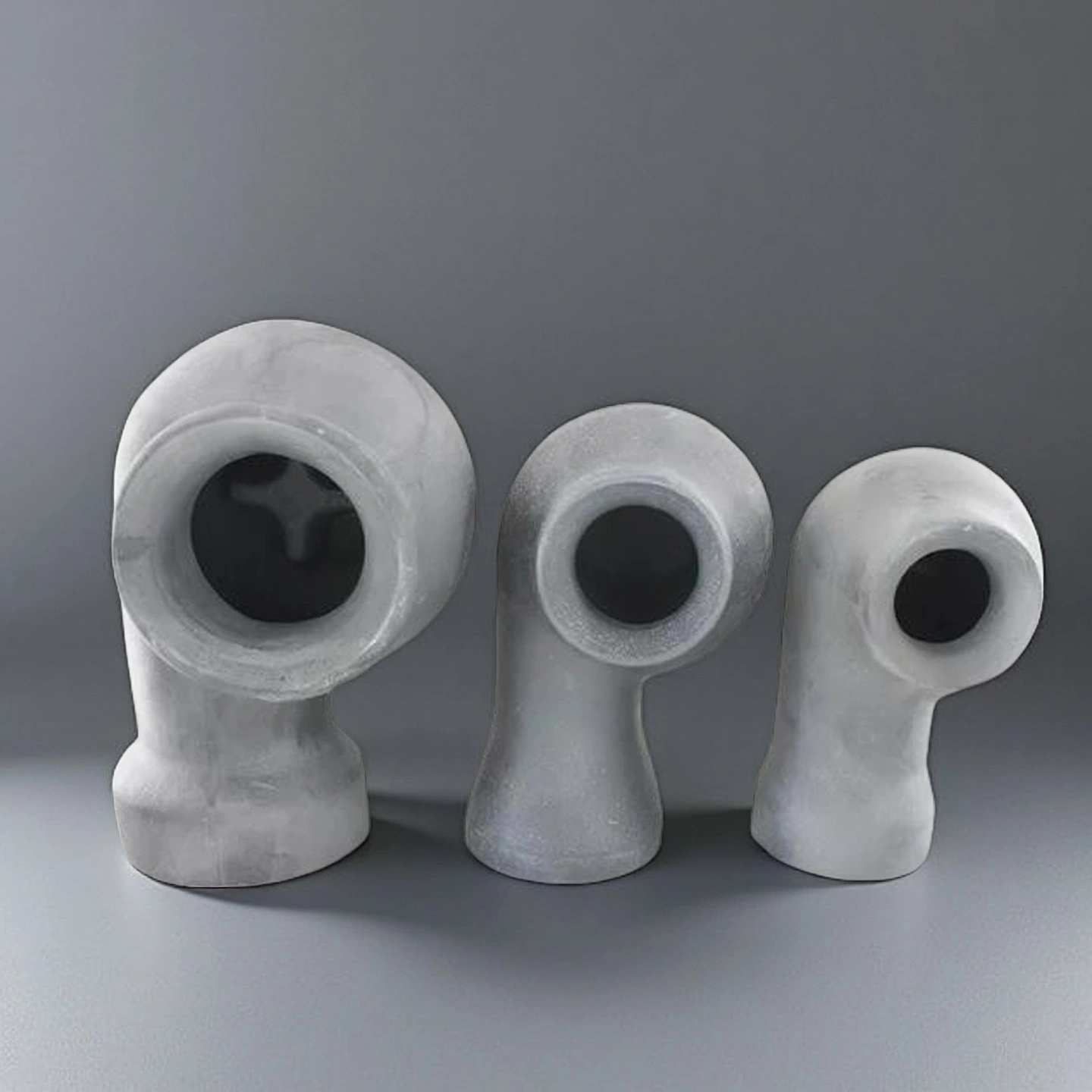

What Is a Vortex Silicon Carbide Spray Nozzle?
A vortex silicon carbide spray nozzle is a ceramic spray component designed to create a controlled rotational flow before the liquid exits the nozzle. This flow structure helps form a stable full-cone or controlled spray pattern in wet FGD absorbers, scrubbers, gas-cooling towers and quench systems.
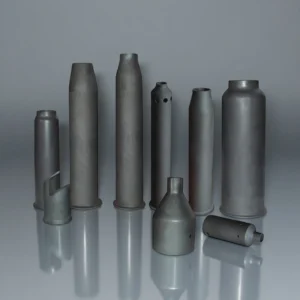
Compared with metallic or polymer nozzles, a SiC spray nozzle is selected when the process involves abrasive slurry, acidic condensate, chloride exposure, thermal fluctuation or high-dust gas streams. ADCERAX supports drawing-based customization for nozzle geometry, connection style, material grade and application-specific dimensions.
Why Use Silicon Carbide for Industrial Spray Nozzles?
Silicon carbide is used for industrial spray nozzles because it combines high hardness, corrosion resistance, thermal stability and dimensional retention. These properties help the nozzle maintain its outlet geometry and spray behavior when exposed to abrasive particles, acidic liquids and temperature changes.
For wet FGD and gas-scrubbing systems, nozzle geometry directly affects droplet distribution, gas–liquid contact and coverage inside the absorber. A stable SiC nozzle body can reduce the risk of deformation, clogging-related flow changes and uneven spray coverage when the system operates under demanding process conditions.
-
Material System
ADCERAX can review vortex silicon carbide spray nozzles in RBSiC or SSiC material options according to the working media, corrosion level, wear condition and machining requirements. The correct material grade helps the nozzle maintain stable geometry in abrasive slurry, acidic condensate and demanding gas-treatment environments.
-
Spray Pattern
The nozzle can be designed for full-cone or custom vortex spray patterns. Spray pattern selection should be matched with absorber size, scrubber layout, quench tower coverage, liquid flow rate and gas–liquid contact requirements.
-
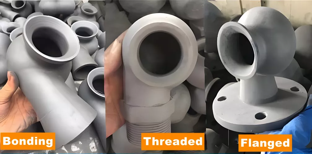
Connection Type
Threaded, flanged, sleeve and drawing-based connection structures can be reviewed for different installation systems. A suitable connection design helps the SiC nozzle fit existing piping, spray headers and replacement assemblies with fewer installation risks.
-
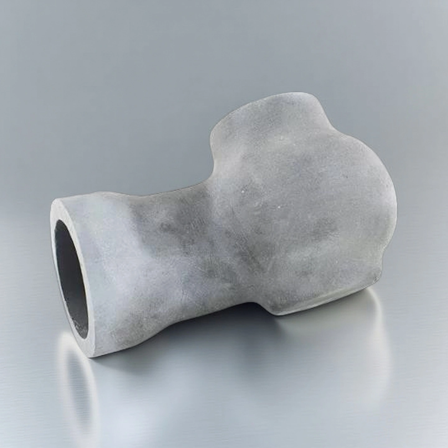
Flow Path Design
The internal vortex chamber, outlet profile and flow passage directly affect atomization stability, flow consistency and spray coverage. For replacement projects, the existing nozzle drawing or sample is helpful for confirming the critical dimensions and internal geometry.
-
Application Media
These nozzles are commonly reviewed for limestone slurry, acidic condensate, wash liquid and high-dust gas-flow environments. The working media, solid content, temperature range and pressure condition should be confirmed before material and geometry selection.
Technical Specifications of Vortex Silicon Carbide Spray Nozzle
ADCERAX Vortex Silicon Carbide Spray Nozzle is engineered with stable SiC microstructures and vortex-driven flow behavior, enabling consistent atomization, high durability, and reliable performance in abrasive and chemically aggressive flue-gas environments. Its material and functional characteristics support long-cycle operation in industrial desulfurization and gas-scrubbing systems.
| Property | Specification | Engineering Relevance |
|---|---|---|
| Material Type | Reactive Bonded SiC (RBSiC) / Sintered SiC (SSiC) | RBSiC and SSiC can be reviewed according to corrosion level, abrasive slurry condition, temperature range and project cost target. |
| Density | ≥3.00 g/cm³ (RBSiC); ≥3.10–3.15 g/cm³ (SSiC) | Higher density generally supports better structural integrity and lower open porosity, which is important for corrosive spray environments. |
| Flexural Strength | 250–350 MPa (RBSiC); 400+ MPa (SSiC) | Flexural strength affects resistance to handling stress, installation load and mechanical vibration during operation. |
| Hardness | HRA 88–92 | High hardness helps the nozzle resist erosion from limestone slurry, suspended particles and high-velocity liquid flow. |
| Fracture Toughness | 3–4 MPa·m¹/² | Fracture toughness helps reduce cracking risk during installation, thermal fluctuation and impact from process particles. |
| Open Porosity | ≤1% typical for RBSiC | Lower porosity helps limit liquid penetration and supports more stable corrosion and wear behavior. |
| Thermal Conductivity | 90–120 W/m·K at 25°C, depending on SiC grade | Good thermal conductivity helps the nozzle handle temperature variation in quench towers and gas-treatment systems. |
| Maximum Service Temperature | ≥1400°C in non-oxidizing industrial environments | This reference value supports use in demanding thermal environments, but final suitability should be confirmed by atmosphere, media and nozzle design. |
| Thermal Shock Resistance | ΔT 250–300°C, depending on grade and geometry | Thermal shock resistance is important when the nozzle experiences rapid temperature changes during start-up, shutdown or quench operation. |
| Corrosion Resistance in Acidic Media | Stable in many chloride, acidic slurry and SO₂/SO₃ exposure conditions | Corrosion behavior depends on acid concentration, chloride level, temperature and contact time, so application review is recommended before selection. |
| Wear Resistance in Abrasive Slurry | Suitable for abrasive slurry and particle-loaded liquid flow | Wear resistance helps maintain outlet geometry, spray angle and flow consistency over the service period. |
| Chemical Resistance | Stable in SO₂/SO₃, chlorides, HF and acidic slurries under suitable conditions | Chemical resistance makes SiC suitable for wet FGD, scrubbers, waste-gas cleaning and other corrosive process lines. |
| Surface Friction Coefficient | Low-friction ceramic surface, depending on finish and media | A smoother flow surface can help reduce slurry deposition and support more consistent liquid discharge. |
| Spray-Angle Stability | Designed to maintain spray geometry under controlled pressure fluctuation | Stable spray angle helps maintain absorber coverage, gas–liquid contact and process consistency. |
| Flow-Rate Deviation | Controlled according to drawing, outlet geometry and rated operating pressure | Flow consistency depends on machining accuracy, outlet profile, pressure condition and installation layout. |
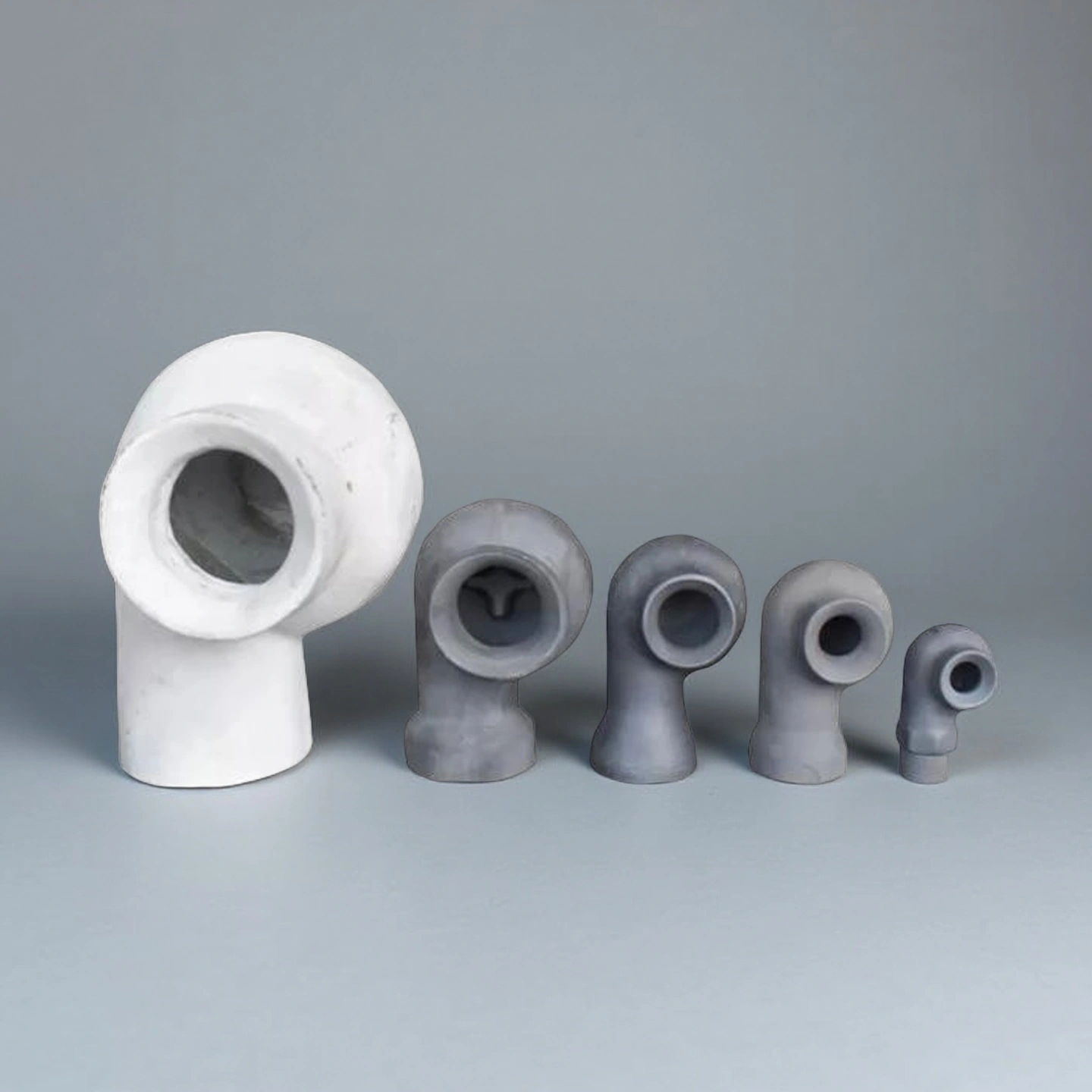
Reference Sizes for Vortex Silicon Carbide Spray Nozzle
The following vortex silicon carbide spray nozzle sizes are reference options for early selection. Final availability, flow rate, outlet geometry, connection method and lead time should be confirmed according to drawings, operating pressure, working media and required quantity.
| Silicon Carbide Swirl Nozzle | |||||
| Model | Inch | Outlet Diameter (mm) | Flow Rate Range (m³/h) | Coverage Diameter (m) | Connection Method |
| AT-THG-DN10 | 3/8 inch | 13 | 1-2 | 1.1-1.2 | Bonding/Threaded/Flange |
| AT-THG-DN15 | 1/2 inch | 16 | 2-3 | 1.2-1.3 | Bonding/Threaded/Flange |
| AT-THG-DN20 | 3/4 inch | 18 | 3-5 | 1.2-1.3 | Bonding/Threaded/Flange |
| AT-THG-DN25C | 1 inch | 20 | 5-6 | 1.3-1.35 | Bonding/Threaded/Flange |
| AT-THG-DN25B | 1 inch | 25 | 6-8 | 1.3-1.4 | Bonding/Threaded/Flange |
| AT-THG-DN25A | 1 inch | 25 | 7-10 | 1.4 | Bonding/Threaded/Flange |
| AT-THG-DN32 | 1.2 inch | 30 | 9-11 | 1.4-1.45 | Bonding/Threaded/Flange |
| AT-THG-DN40B | 1.5 inch | 30 | 11-13 | 1.45 | Bonding/Threaded/Flange |
| AT-THG-DN40A | 1.5 inch | 35 | 13-15 | 1.5 | Bonding/Threaded/Flange |
| AT-THG-DN50A | 2 inch | 45 | 20-25 | 1.6 | Bonding/Threaded/Flange |
| AT-THG-DN50B | 2 inch | 40 | 16.5-20 | 1.6-1.7 | Bonding/Threaded/Flange |
| AT-THG-DN50c | 2 inch | 40 | 15-16.5 | 1.7-1.8 | Bonding/Threaded/Flange |
| AT-THG-DN50 | 2 inch | 50 | 25-30 | 1.8 | Bonding/Threaded/Flange |
| AT-THG-DN65 | 2.5 inch | 45 | 20-25 | 1.8-1.9 | Bonding/Threaded/Flange |
| AT-THG-DN80A | 3 inch | 50 | 25-30 | 1.8-2 | Bonding/Threaded/Flange |
| AT-THG-DN80B | 3 inch | 55 | 30-35 | 1.8-2 | Bonding/Threaded/Flange |
| AT-THG-DN100D | 4 inch | 65 | 35-40 | 1.8-2 | Bonding/Threaded/Flange |
| AT-THG-DN100C | 4 inch | 70 | 50-55 | 1.8-2 | Bonding/Threaded/Flange |
| AT-THG-DN100B | 4 inch | 75 | 55-60 | 1.8-2 | Bonding/Threaded/Flange |
| AT-THG-DN100A | 4 inch | 80 | 65-70 | 1.8-2 | Bonding/Threaded/Flange |
| AT-THG-DN125 | 5 inch | Custom | Customized on demand | 2 meters and above | Bonding/Threaded/Flange |
| AT-THG-DN150 | 6 inch | Custom | Customized on demand | 2 meters and above | Bonding/Threaded/Flange |
| Silicon Carbide Swirl Nozzle with Double Head | |||||
| Item No. | Inch | Single Outlet Inner Diameter (mm) | Flow Rate Range (m³/h) | Coverage Diameter (m) | Remarks |
| AT-THG-SPZ001 | 1 inch | 20 | 10-12 | 2.3-2.4 | Single-direction Double Head |
| AT-THG-SPZ002 | 1.5 inch | 30 | 22-24 | 2.6 | Double-direction Double Head |
| AT-THG-SPZ003 | 2 inch | 45 | 20-36 | 2.8-3.0 | Single-direction Double Head |
| AT-THG-SPZ004 | 2 inch | 45 | 40 | 3 | Double-direction Double Head |
| AT-THG-SPZ005 | 2.5 inch | 48 | 20-45 | 3.6-3.8 | Single-direction Double Head |
| AT-THG-SPZ006 | 2.5 inch | 48 | 42 | 3.6-3.8 | Double-direction Double Head |
| AT-THG-SPZ007 | 3 inch | 50 | 25-45 | 3.6-4 | Single-direction Double Head |
| AT-THG-SPZ008 | 3 inch | 50 | 50 | 3.6-4 | Double-direction Double Head |
| AT-THG-SPZ009 | 4 inch | 65 | 35-65 | 3.6-4 | Single-direction Double Head |
| AT-THG-SPZ010 | 4 inch | 65 | 70 | 3.6-4 | Double-direction Double Head |
How to Select the Right SiC Spray Nozzle
To select a suitable silicon carbide spray nozzle, the buyer should confirm both the process conditions and the mechanical interface. A correct material choice alone is not enough. Spray behavior also depends on outlet geometry, flow path, connection type and installation position.
For faster review, please provide the nozzle drawing, target flow rate, spray pattern, working media, solid content, temperature range, pressure range, connection type and required quantity. ADCERAX will review whether RBSiC, SSiC or another ceramic solution is more suitable for the application.
Please provide the following information for quotation:
• Drawing or sample photos
• Material grade requirement, if known
• Spray pattern and flow rate
• Working liquid or slurry composition
• Solid content or particle condition
• Temperature and pressure range
• Thread, flange or mounting interface
• Quantity and project schedule
Packaging of Vortex Silicon Carbide Spray Nozzle
Vortex Silicon Carbide Spray Nozzle is packaged in reinforced foam-lined compartments to prevent movement and protect all critical spray surfaces during transportation. Each nozzle is individually separated by high-density insulation material to avoid surface friction and impact during handling. The packing structure ensures stable support throughout long-distance export shipments, maintaining product integrity upon arrival at the end-user’s facility.