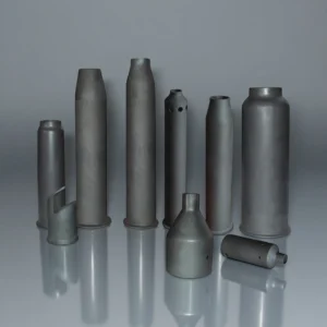
What Are Silicon Carbide Heat Exchanger Tubes?
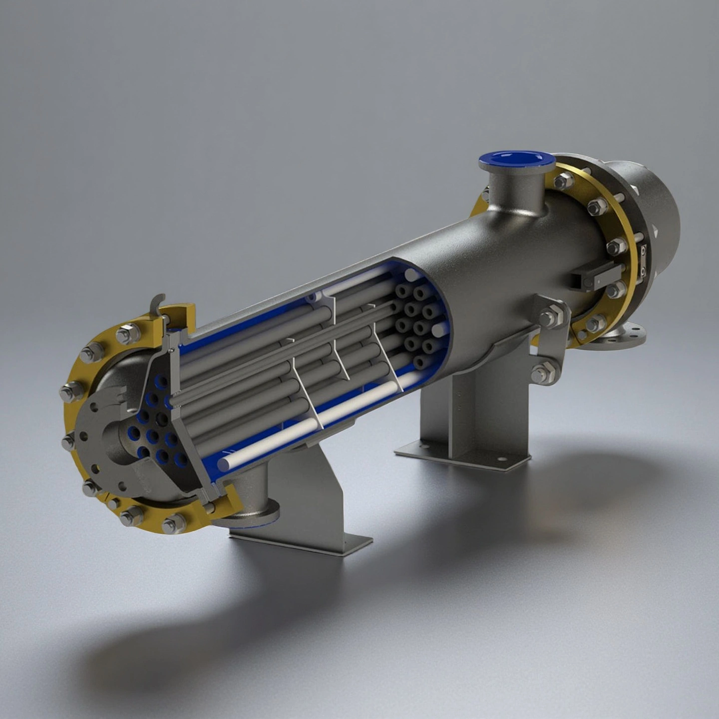
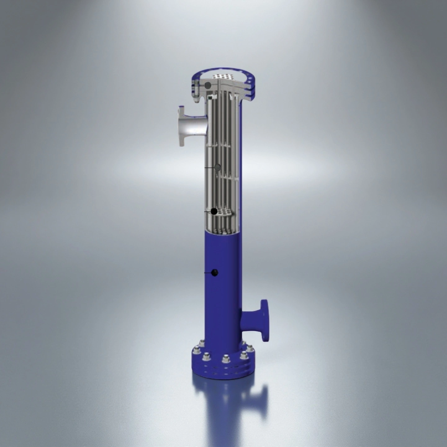
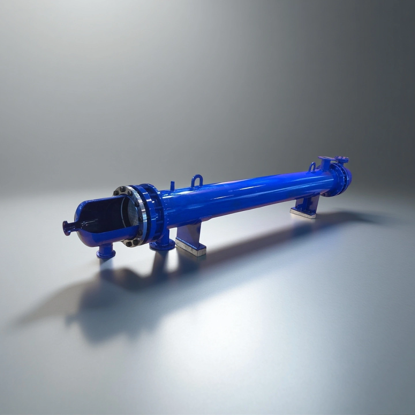
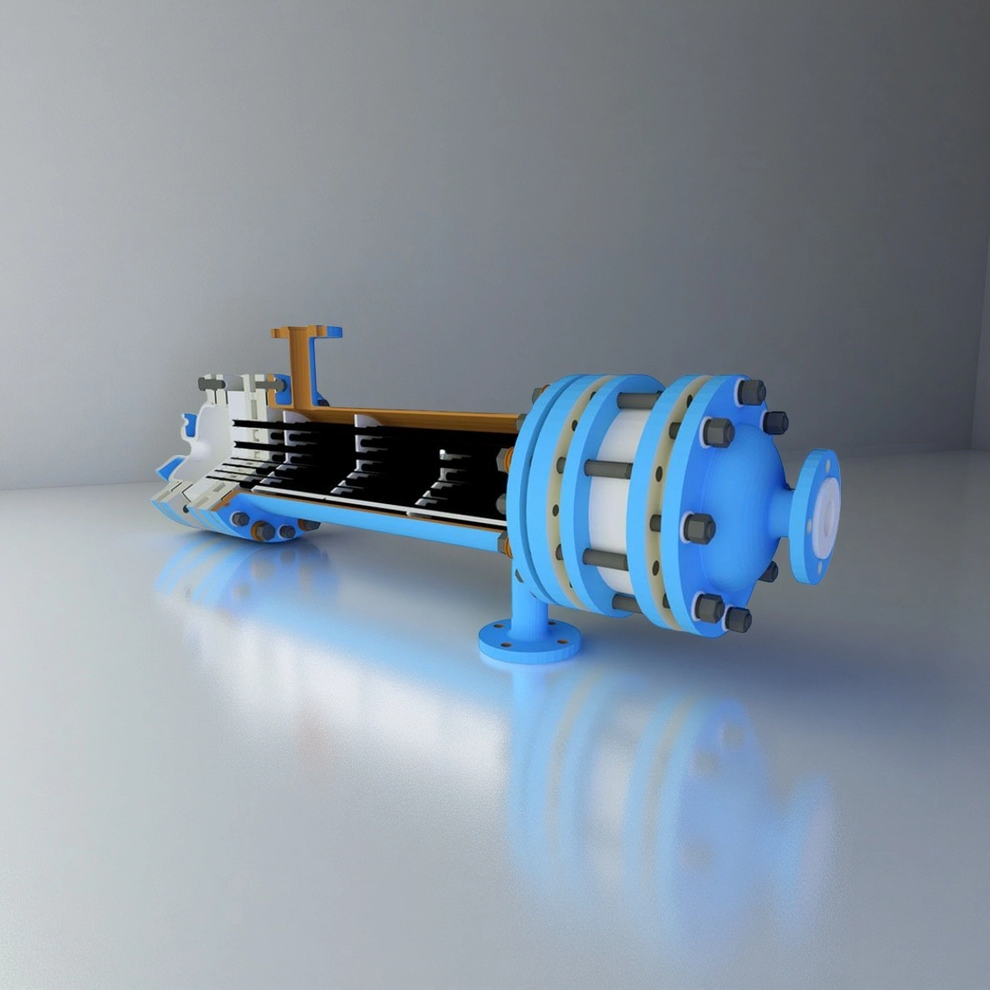
Silicon carbide heat exchanger tubes are ceramic heat-transfer components used in shell-and-tube, tube-bundle or custom heat-recovery assemblies. They separate process media while transferring heat through the SiC tube wall or channel structure.
Compared with many metallic materials, silicon carbide offers strong corrosion resistance, high hardness, thermal conductivity and dimensional stability. This makes it suitable for heat-exchange systems exposed to acids, halogen-containing media, abrasive particles or repeated thermal cycling.
For each project, the correct SiC grade, tube size, channel design and sealing method should be selected according to the process media, temperature range, pressure condition, flow velocity and cleaning method.
Performance Advantages of Silicon Carbide Heat Exchanger Tubes
- Corrosion Resistance
Helps resist acid, oxidizing and corrosive process media in chemical cooling, acid recovery and flue-gas treatment systems. - Stable Heat Transfer
High thermal conductivity supports efficient heat exchange while maintaining ceramic stability in harsh media. - Low Porosity
Dense SiC helps reduce media penetration, contamination risk and chemical attack inside the ceramic body. - Thermal Cycling Stability
Low thermal expansion helps reduce thermal stress during repeated heating and cooling cycles. - Abrasion Resistance
High hardness improves resistance to slurry, dust, crystals and particle-containing gas or liquid flow. - Mechanical Stability
Proper wall thickness, support spacing and sealing design help maintain tube stability during operation. - Maintenance Risk Reduction
Suitable material matching can reduce corrosion-related replacement and unplanned maintenance risk.
Technical Specifications of Silicon Carbide Heat Exchanger Tube
ADCERAX® Silicon Carbide Heat Exchanger Tubes are engineered for stable performance under high-corrosion, high-thermal-load, and high-purity operating environments, combining dense SiC microstructure, strong thermal conduction, and reliable mechanical integrity required for demanding industrial heat-exchange systems.
| Performance Parameter | Typical Reference Value | Engineering Explanation |
|---|---|---|
| Thermal Conductivity | 45–120 W/m·K | Higher thermal conductivity supports faster heat transfer and helps improve heat-exchange efficiency in compact equipment designs. |
| Bulk Density | 2.95–3.15 g/cm³ | Higher density indicates a denser SiC ceramic body, which supports corrosion resistance, mechanical strength and lower media penetration risk. |
| Open Porosity | ≤0.2% for dense SiC grades | Lower porosity helps reduce liquid penetration, contamination risk and chemical attack inside the ceramic structure. |
| Flexural Strength | 250–450 MPa | Higher bending strength helps the tube resist handling stress, assembly load and operating stress during service. |
| Compressive Strength | 2000–2500 MPa | High compressive strength supports structural stability under clamping, sealing and pressure-related loads. |
| Hardness | Mohs 9–9.5 / HV 2400–2800 | High hardness improves resistance to abrasive particles, slurry flow and solid-containing gas streams. |
| Elastic Modulus | 380–410 GPa | A high modulus helps maintain dimensional stability, but also means the tube design should avoid concentrated mechanical stress. |
| Thermal Expansion Coefficient | 4.0–4.5 × 10⁻⁶/K | Low thermal expansion helps reduce thermal deformation and supports dimensional stability during heating and cooling cycles. |
| Maximum Service Temperature | 1300–1650°C, grade-dependent | The usable temperature depends on SiC grade, atmosphere, load, seal design and thermal cycling condition. |
Dimensions of Silicon Carbide Heat Exchanger Tube
| Calculation of sic heat exchanger tube area (㎡) and length with an outer dia of 14mm | |||||||
| Item No. | Heat Exchanger Mold | Quantities of Heat Exchanger | L=3000mm | L=2500mm | L=2000mm | L=1500mm | L=1000mm |
| AT-THG-HRQ001 | DN100 | 7 | 0.92 | 0.77 | 0.62 | 0.46 | 0.31 |
| AT-THG-HRQ002 | DN150 | 0.1 | 0.15 | 0.2 | 0.2 | 0.3 | 0.15 |
| AT-THG-HRQ003 | DN200 | 31 | 4.09 | 3.41 | 2.73 | 2.05 | 1.36 |
| AT-THG-HRQ004 | DN250 | 0.1 | 0.15 | 0.2 | 0.2 | 0.3 | 0.15 |
| AT-THG-HRQ005 | DN300 | 76 | 10.03 | 8.36 | 6.69 | 5.01 | 3.34 |
| AT-THG-HRQ006 | DN350 | 0.1 | 0.15 | 0.2 | 0.2 | 0.3 | 0.15 |
| AT-THG-HRQ007 | DN400 | 140 | 18.47 | 15.39 | 12.32 | 9.24 | 6.16 |
| AT-THG-HRQ008 | DN450 | 0.1 | 0.15 | 0.2 | 0.2 | 0.3 | 0.15 |
| AT-THG-HRQ009 | DN500 | 230 | 30.35 | 25.29 | 20.23 | 15.17 | 10.12 |
| AT-THG-HRQ010 | DN600 | 0.1 | 0.15 | 0.2 | 0.2 | 0.3 | 0.15 |
| AT-THG-HRQ011 | DN700 | 454 | 59.90 | 49.92 | 39.94 | 29.95 | 19.97 |
| AT-THG-HRQ012 | DN800 | 0.1 | 0.15 | 0.2 | 0.2 | 0.3 | 0.15 |
| AT-THG-HRQ013 | DN900 | 769 | 101.47 | 84.56 | 67.64 | 50.73 | 33.82 |
| AT-THG-HRQ014 | DN1000 | 0.1 | 0.15 | 0.2 | 0.2 | 0.3 | 0.15 |
| AT-THG-HRQ015 | DN1200 | 1393 | 183.80 | 153.17 | 122.53 | 91.90 | 61.27 |
| Calculation of sic heat exchanger tube area (㎡) and length with an outer dia of 19mm | |||||||
| Item No. | Heat Exchanger Mold | Quantities of Heat Exchanger | L=3000mm | L=2500mm | L=2000mm | L=1500mm | L=1000mm |
| AT-THG-HRQ0016 | DN100 | 7 | 1.25 | 1.04 | 0.84 | 0.63 | 0.42 |
| AT-THG-HRQ0017 | DN150 | 13 | 2.33 | 1.94 | 1.55 | 1.16 | 0.78 |
| AT-THG-HRQ0018 | DN200 | 22 | 3.94 | 3.28 | 2.63 | 1.97 | 1.31 |
| AT-THG-HRQ0019 | DN250 | 38 | 6.80 | 5.67 | 4.54 | 3.40 | 2.27 |
| AT-THG-HRQ0020 | DN300 | 55 | 9.85 | 8.21 | 6.57 | 4.92 | 3.28 |
| AT-THG-HRQ0021 | DN350 | 73 | 13.07 | 10.89 | 8.71 | 6.54 | 4.36 |
| AT-THG-HRQ0022 | DN400 | 96 | 17.19 | 14.33 | 11.46 | 8.60 | 5.73 |
| AT-THG-HRQ0023 | DN450 | 126 | 22.56 | 18.80 | 15.04 | 11.28 | 7.52 |
| AT-THG-HRQ0024 | DN500 | 151 | 27.04 | 22.53 | 18.03 | 13.52 | 9.01 |
| AT-THG-HRQ0025 | DN600 | 230 | 41.19 | 34.32 | 27.46 | 20.59 | 13.73 |
| AT-THG-HRQ0026 | DN700 | 316 | 56.59 | 47.16 | 37.72 | 28.29 | 18.86 |
| AT-THG-HRQ0027 | DN800 | 421 | 75.39 | 62.82 | 50.26 | 37.69 | 25.13 |
| AT-THG-HRQ0028 | DN900 | 526 | 74.19 | 78.49 | 62.79 | 47.10 | 31.40 |
| AT-THG-HRQ0029 | DN1000 | 649 | 116.22 | 96.85 | 77.48 | 58.11 | 38.74 |
| AT-THG-HRQ0030 | DN1200 | 955 | 171.01 | 142.51 | 114.01 | 85.51 | 57.00 |
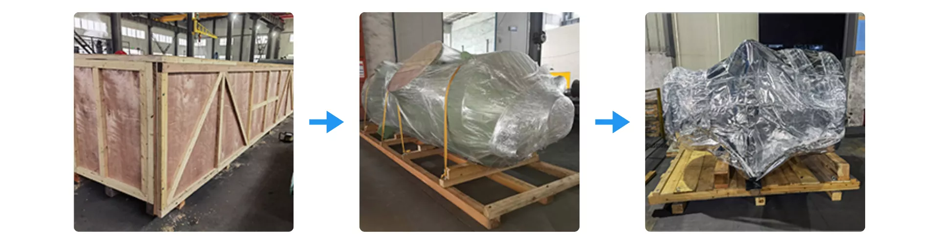
Packaging Process for Silicon Carbide Heat Exchanger Tubes
Silicon Carbide Heat Exchanger Tubes are secured using reinforced wooden crating to protect the module during long-distance international transport. Each unit is wrapped with multi-layer moisture-barrier film and fixed onto a vibration-resistant wooden base to prevent structural stress. The exterior crate is further sealed and braced to ensure safe handling during loading, unloading, and maritime shipment.