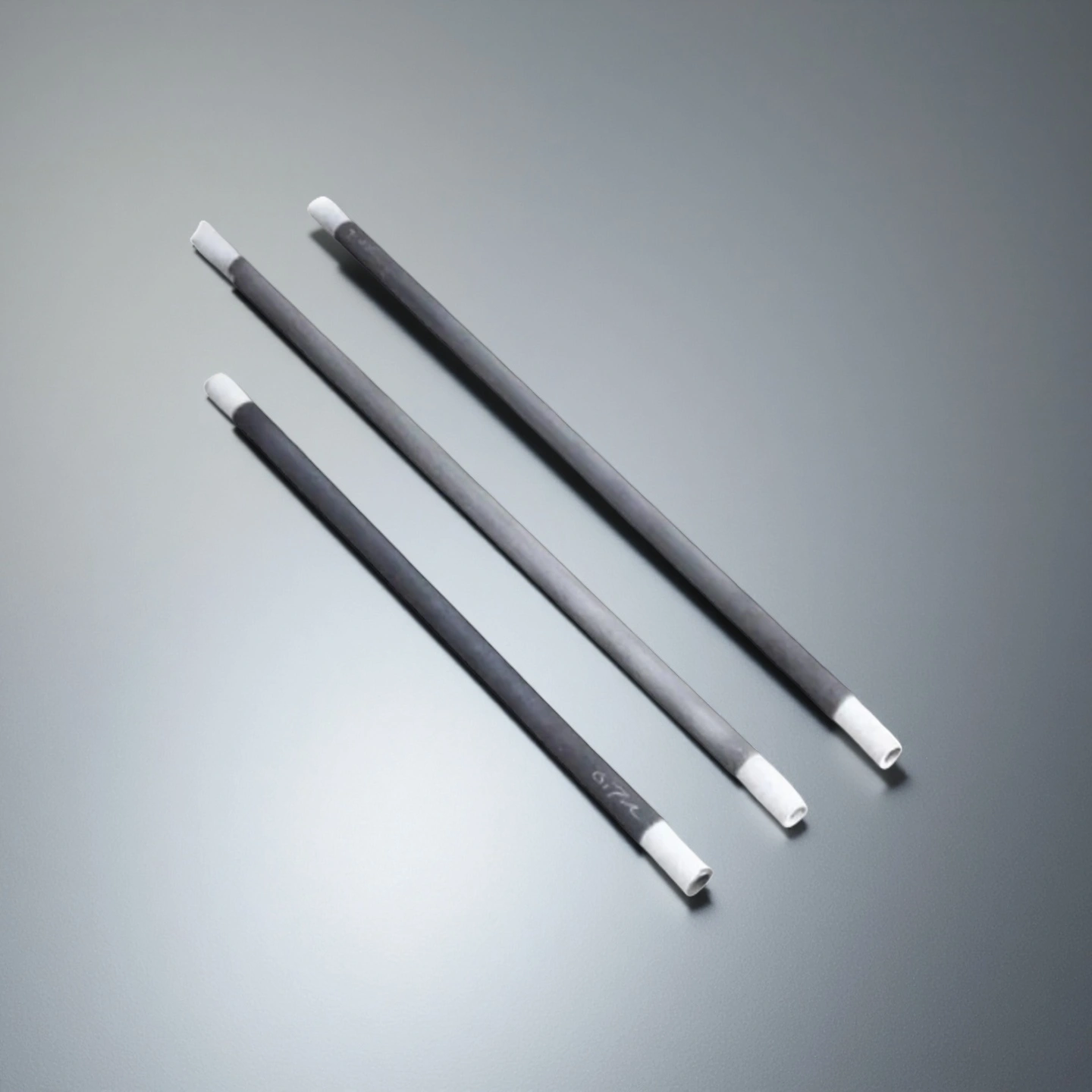
ADCERAX® Silicon Carbide Heating Tube is manufactured from high-purity green SiC and carbon additives through ultra-high-temperature siliconization, forming a recrystallized structure with strong oxidation resistance, high thermal conductivity and excellent tolerance to acidic or alkaline furnace atmospheres. These inherent material characteristics enable rapid temperature rise, stable electrical behavior and high surface watt loading, allowing the heating element to maintain uniform thermal profiles while withstanding repeated thermal cycling. As a result, the tube delivers long service life and supports precise temperature control when integrated into automated heating systems, ensuring consistent performance for demanding industrial heat-treatment and sintering processes.
High-Temperature Performance Features of the Silicon Carbide Heating Tube
-
Resistance to Aggressive Atmospheres
Engineered to maintain structural integrity under acidic and alkaline vapors, showing measurable stability after 500+ furnace hours in mixed-gas environments. Its protective silica layer formation reduces surface degradation by over 30% compared with metal-based heating elements. -
Long-Term Oxidation Stability
Validated oxidation resistance ensures consistent electrical behavior over extended cycles, with resistance drift typically controlled below ±5% after 1000 hours of elevated-temperature exposure. This stability supports predictable furnace performance in high-duty operations. -
Reduced Maintenance Frequency
Proven corrosion resistance reduces replacement intervals, cutting downtime by 20–35% in heat-treatment applications requiring frequent thermal cycling. The extended service behavior improves overall operational efficiency for continuous thermal processes. -
Fast Heating Response
High surface watt density enables rapid temperature rise, reducing heat-up time by 25–40% compared to Fe-Cr-Al alloy heaters. This accelerated response improves cycle throughput in sintering and heat-treatment workflows. -
Improved Energy Efficiency
Optimized heat conduction reduces energy consumption, with furnace operators reporting 8–15% lower power usage for equivalent temperature curves. Such efficiency gains are particularly beneficial in multi-shift continuous operation environments. -
Resistance to Rapid Temperature Change
Low thermal expansion coefficients minimize internal stress, allowing the tube to withstand abrupt heating and cooling cycles exceeding 300–500°C/min without structural failure. This robustness supports demanding duty cycles in laboratory and industrial furnaces. -
High Operating Temperature Capability
Capable of continuous service at up to 1600°C in air, the material provides stable performance without protective atmospheres. This temperature tolerance surpasses conventional metal heaters by 600–800°C, enabling more advanced thermal processes.
Technical Specifications of Silicon Carbide Heating Tube
The Silicon Carbide Heating Tube is engineered with a recrystallized SiC structure designed for stable high-temperature operation, consistent electrical behavior, and reliable thermal performance in demanding industrial furnace environments.
| Property | Specification |
|---|---|
| Material Grade | Recrystallized Silicon Carbide (RSiC) |
| Maximum Service Temperature | 1600 °C continuous, up to 1700 °C peak |
| Thermal Conductivity | 25–35 W/m·K at elevated temperatures |
| Thermal Expansion Coefficient | 4.5–5.0 × 10⁻⁶/K (25–1000 °C) |
| Flexural Strength | ≥ 45 MPa at room temperature |
| Density | 2.60–2.75 g/cm³ |
| Electrical Resistivity | 0.08–0.12 Ω·cm at 1000 °C |
| Surface Watt Loading Capability | 8–12 W/cm² depending on configuration |
| Oxidation Resistance | Stable SiO₂ film formation up to 1500 °C |
| Thermal Shock Resistance | Withstands 300–500 °C/min rapid cycling |
| Chemical Resistance | Acid/alkali/oxide-gas resistant (SiC oxidation rate <0.1 mg/cm²·h) |
| Service Life Expectation | 2000+ hours under standard furnace atmosphere |
Dimensions of Silicon Carbide Heating Tube
Type 1-Silicon Carbide Heating Element Single Helical

| Single Spiral Heating Type | OD / mm | Heating zone / mm | Cold zone/ mm | Overall length /mm | Hot zone surface area / cm² | voltage / V | Power / W | Range of resistance Ω (±20%) | Purity |
| AT-THG-BA001 | 14 | 200 | 200 | 600 | 87 | 59 | 1650 | 2.11 | 99% |
| AT-THG-BA002 | 14 | 200 | 250 | 700 | 87 | 60 | 1680 | 2.14 | 99% |
| AT-THG-BA003 | 14 | 250 | 200 | 650 | 109 | 71 | 1990 | 2.53 | 99% |
| AT-THG-BA004 | 14 | 250 | 250 | 750 | 109 | 73 | 2040 | 2.61 | 99% |
| AT-THG-BA005 | 14 | 300 | 250 | 800 | 131 | 85 | 2380 | 3.04 | 99% |
| AT-THG-BA006 | 16 | 200 | 250 | 700 | 100 | 58 | 1970 | 1.71 | 99% |
| AT-THG-BA007 | 16 | 250 | 200 | 650 | 125 | 69 | 2350 | 2.03 | 99% |
| AT-THG-BA008 | 16 | 250 | 250 | 750 | 125 | 70 | 2380 | 2.06 | 99% |
| AT-THG-BA009 | 16 | 250 | 300 | 850 | 125 | 71 | 2410 | 2.09 | 99% |
| AT-THG-BA010 | 16 | 300 | 200 | 700 | 150 | 81 | 2750 | 2.39 | 99% |
| AT-THG-BA011 | 16 | 300 | 250 | 800 | 150 | 82 | 2790 | 2.41 | 99% |
| AT-THG-BA012 | 16 | 300 | 300 | 900 | 150 | 83 | 2820 | 2.44 | 99% |
| AT-THG-BA013 | 16 | 350 | 250 | 850 | 175 | 94 | 3200 | 2.76 | 99% |
| AT-THG-BA014 | 16 | 350 | 300 | 950 | 175 | 95 | 3230 | 2.79 | 99% |
| AT-THG-BA015 | 20 | 300 | 400 | 1100 | 188 | 84 | 3440 | 2.05 | 99% |
| AT-THG-BA016 | 20 | 350 | 400 | 1150 | 219 | 97 | 3980 | 2.36 | 99% |
| AT-THG-BA017 | 20 | 400 | 400 | 1200 | 251 | 109 | 4470 | 2.66 | 99% |
| AT-THG-BA018 | 20 | 450 | 400 | 1250 | 282 | 121 | 4960 | 2.95 | 99% |
| AT-THG-BA019 | 25 | 300 | 400 | 1100 | 235 | 84 | 4120 | 1.71 | 99% |
| AT-THG-BA020 | 25 | 300 | 500 | 1300 | 235 | 86 | 4210 | 1.76 | 99% |
| AT-THG-BA021 | 25 | 400 | 400 | 1200 | 314 | 110 | 5390 | 2.24 | 99% |
| AT-THG-BA022 | 25 | 500 | 400 | 1300 | 392 | 135 | 6620 | 2.75 | 99% |
| AT-THG-BA023 | 30 | 300 | 400 | 1100 | 282 | 79 | 4980 | 1.25 | 99% |
| AT-THG-BA024 | 30 | 300 | 500 | 1300 | 282 | 80 | 5040 | 1.27 | 99% |
| AT-THG-BA025 | 30 | 400 | 400 | 1200 | 376 | 103 | 6490 | 1.63 | 99% |
| AT-THG-BA026 | 30 | 400 | 500 | 1400 | 376 | 104 | 6550 | 1.65 | 99% |
| AT-THG-BA027 | 30 | 500 | 400 | 1300 | 471 | 127 | 8000 | 2.02 | 99% |
| AT-THG-BA028 | 30 | 600 | 400 | 1400 | 565 | 151 | 9510 | 2.4 | 99% |
| AT-THG-BA029 | 35 | 400 | 400 | 1200 | 439 | 101 | 7680 | 1.33 | 99% |
| AT-THG-BA030 | 35 | 400 | 500 | 1400 | 439 | 102 | 7750 | 1.34 | 99% |
| AT-THG-BA031 | 35 | 500 | 400 | 1300 | 549 | 124 | 9420 | 1.63 | 99% |
| AT-THG-BA032 | 35 | 500 | 500 | 1500 | 549 | 125 | 9500 | 1.64 | 99% |
| AT-THG-BA033 | 35 | 600 | 400 | 1400 | 659 | 148 | 11200 | 1.96 | 99% |
| AT-THG-BA034 | 35 | 700 | 400 | 1500 | 769 | 171 | 13000 | 2.25 | 99% |
| AT-THG-BA035 | 40 | 500 | 400 | 1300 | 628 | 116 | 10700 | 1.26 | 99% |
| AT-THG-BA036 | 40 | 500 | 500 | 1500 | 628 | 117 | 10800 | 1.27 | 99% |
| AT-THG-BA037 | 40 | 600 | 400 | 1400 | 753 | 138 | 12700 | 1.5 | 99% |
| AT-THG-BA038 | 40 | 700 | 400 | 1500 | 879 | 161 | 14800 | 1.75 | 99% |
| AT-THG-BA039 | 45 | 700 | 450 | 1600 | 989 | 149 | 16800 | 1.32 | 99% |
| AT-THG-BA040 | 45 | 800 | 400 | 1600 | 1130 | 168 | 19000 | 1.49 | 99% |
Type 2-Silicon Carbide Heating Element Double Helical

| Double Spiral Heating Type | OD (mm) | Heat zone (mm) | Cold zone (mm) | Overall length (mm) | Heating zone (cm²) | voltage (V) | Power (W) | Range of resistance Ω (±20%) | Purity |
| AT-THG-BB001 | 16 | 100 | 150 | 250 | 50 | 61 | 940 | 3.96 | 99% |
| AT-THG-BB002 | 16 | 100 | 200 | 300 | 50 | 69 | 1060 | 4.49 | 99% |
| AT-THG-BB003 | 16 | 150 | 150 | 300 | 75 | 84 | 1290 | 5.47 | 99% |
| AT-THG-BB004 | 16 | 150 | 250 | 400 | 75 | 99 | 1520 | 6.45 | 99% |
| AT-THG-BB005 | 16 | 200 | 200 | 400 | 100 | 113 | 1740 | 7.34 | 99% |
| AT-THG-BB006 | 16 | 250 | 200 | 450 | 125 | 135 | 2080 | 8.76 | 99% |
| AT-THG-BB007 | 20 | 100 | 150 | 250 | 62 | 58 | 1110 | 3.03 | 99% |
| AT-THG-BB008 | 20 | 100 | 250 | 350 | 62 | 72 | 1380 | 3.76 | 99% |
| AT-THG-BB009 | 20 | 150 | 200 | 350 | 94 | 87 | 1670 | 4.53 | 99% |
| AT-THG-BB010 | 20 | 200 | 200 | 400 | 125 | 109 | 2090 | 5.68 | 99% |
| AT-THG-BB011 | 20 | 250 | 150 | 400 | 157 | 124 | 2380 | 6.46 | 99% |
| AT-THG-BB012 | 20 | 250 | 250 | 500 | 157 | 138 | 2650 | 7.19 | 99% |
| AT-THG-BB013 | 20 | 300 | 250 | 550 | 188 | 160 | 3070 | 8.34 | 99% |
| AT-THG-BB014 | 25 | 150 | 200 | 350 | 117 | 87 | 2000 | 3.78 | 99% |
| AT-THG-BB015 | 25 | 200 | 200 | 400 | 157 | 110 | 2530 | 4.78 | 99% |
| AT-THG-BB016 | 25 | 200 | 300 | 500 | 157 | 121 | 2780 | 5.27 | 99% |
| AT-THG-BB017 | 25 | 300 | 300 | 600 | 235 | 167 | 3840 | 7.26 | 99% |
| AT-THG-BB018 | 25 | 300 | 400 | 700 | 235 | 179 | 4120 | 7.78 | 99% |
| AT-THG-BB019 | 25 | 350 | 300 | 650 | 274 | 191 | 4390 | 8.31 | 99% |
| AT-THG-BB020 | 25 | 400 | 300 | 700 | 314 | 214 | 4920 | 9.31 | 99% |
| AT-THG-BB021 | 30 | 200 | 200 | 400 | 188 | 190 | 2790 | 2.9 | 99% |
| AT-THG-BB022 | 30 | 250 | 200 | 450 | 235 | 111 | 3440 | 3.58 | 99% |
| AT-THG-BB023 | 30 | 300 | 300 | 600 | 282 | 132 | 4090 | 4.26 | 99% |
| AT-THG-BB024 | 30 | 350 | 350 | 700 | 329 | 153 | 4740 | 4.94 | 99% |
| AT-THG-BB025 | 30 | 400 | 400 | 800 | 376 | 174 | 5390 | 5.62 | 99% |
| AT-THG-BB026 | 30 | 450 | 350 | 800 | 424 | 194 | 6010 | 6.26 | 99% |
| AT-THG-BB027 | 30 | 500 | 300 | 800 | 471 | 214 | 6630 | 6.91 | 99% |
| AT-THG-BB028 | 35 | 200 | 200 | 400 | 219 | 89 | 3260 | 2.43 | 99% |
| AT-THG-BB029 | 35 | 250 | 200 | 450 | 274 | 109 | 3990 | 2.98 | 99% |
| AT-THG-BB030 | 35 | 300 | 300 | 600 | 329 | 130 | 4760 | 3.55 | 99% |
| AT-THG-BB031 | 35 | 400 | 300 | 700 | 439 | 171 | 6260 | 4.67 | 99% |
| AT-THG-BB032 | 35 | 450 | 350 | 800 | 494 | 191 | 6990 | 5.22 | 99% |
| AT-THG-BB033 | 35 | 500 | 300 | 800 | 549 | 211 | 7720 | 5.77 | 99% |
| AT-THG-BB034 | 40 | 200 | 200 | 400 | 251 | 86 | 3660 | 2.02 | 99% |
| AT-THG-BB035 | 40 | 250 | 200 | 450 | 314 | 106 | 4510 | 2.49 | 99% |
| AT-THG-BB036 | 40 | 300 | 300 | 600 | 376 | 127 | 5400 | 2.99 | 99% |
| AT-THG-BB037 | 40 | 350 | 300 | 650 | 439 | 147 | 6250 | 3.46 | 99% |
| AT-THG-BB038 | 40 | 400 | 300 | 700 | 502 | 167 | 7100 | 3.93 | 99% |
| AT-THG-BB039 | 40 | 400 | 400 | 800 | 502 | 167 | 7100 | 3.93 | 99% |
| AT-THG-BB040 | 40 | 450 | 300 | 750 | 565 | 186 | 7910 | 4.37 | 99% |
| AT-THG-BB041 | 40 | 450 | 350 | 800 | 565 | 187 | 7950 | 4.4 | 99% |
| AT-THG-BB042 | 40 | 500 | 300 | 800 | 628 | 206 | 8760 | 4.84 | 99% |
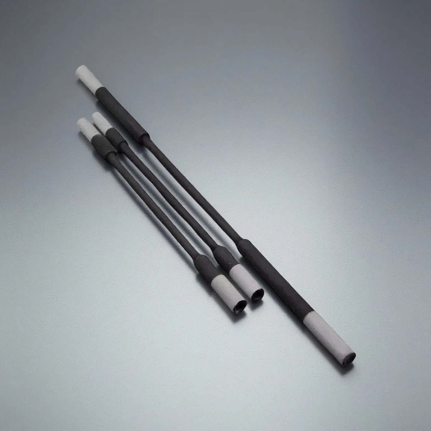
Type 3-Silicon Carbide Heating Element Dumbbell
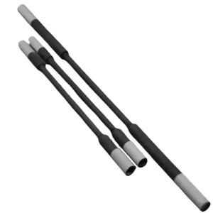
| Sic Heating Element -Rod | Small side OD / mm | Heat zone length / mm | Cold zone length / mm | large side OD / mm | Range of resistance / Ω | Purity |
| AT-THG-BD001 | 8 | 180 | 60 | 14 | 2.6-5.2 | 99% |
| AT-THG-BD002 | 8 | 180 | 150 | 14 | 2.6-5.2 | 99% |
| AT-THG-BD003 | 8 | 150 | 150 | 14 | 2.2-4.5 | 99% |
| AT-THG-BD004 | 8 | 180 | 180 | 14 | 2.6-5.2 | 99% |
| AT-THG-BD005 | 8 | 200 | 150 | 14 | 2.9-5.8 | 99% |
| AT-THG-BD006 | 12 | 150 | 200 | 20 | 1.1-2.2 | 99% |
| AT-THG-BD007 | 12 | 200 | 200 | 20 | 1.4-2.9 | 99% |
| AT-THG-BD008 | 12 | 250 | 200 | 20 | 1.8-3.8 | 99% |
| AT-THG-BD009 | 14 | 180 | 150 | 22 | 1.3-2.3 | 99% |
| AT-THG-BD010 | 14 | 150 | 250 | 22 | 0.9-1.8 | 99% |
| AT-THG-BD011 | 14 | 200 | 250 | 22 | 1.2-2.3 | 99% |
| AT-THG-BD012 | 14 | 250 | 250 | 22 | 1.5-3.0 | 99% |
| AT-THG-BD013 | 14 | 300 | 250 | 22 | 1.8-3.5 | 99% |
| AT-THG-BD014 | 14 | 400 | 350 | 22 | 2.3-4.7 | 99% |
| AT-THG-BD015 | 18 | 300 | 250 | 28 | 1.1-2.2 | 99% |
| AT-THG-BD016 | 18 | 300 | 350 | 28 | 1.1-2.2 | 99% |
| AT-THG-BD017 | 18 | 400 | 250 | 28 | 1.4-2.9 | 99% |
| AT-THG-BD018 | 18 | 500 | 350 | 28 | 1.8-3.6 | 99% |
| AT-THG-BD019 | 18 | 600 | 350 | 28 | 2.1-4.3 | 99% |
| AT-THG-BD020 | 18 | 400 | 400 | 28 | 1.4-2.9 | 99% |
| AT-THG-BD021 | 25 | 400 | 400 | 38 | 0.8-1.7 | 99% |
| AT-THG-BD022 | 25 | 600 | 500 | 38 | 1.3-2.6 | 99% |
| AT-THG-BD023 | 25 | 800 | 450 | 38 | 1.7-3.4 | 99% |
| AT-THG-BD024 | 25 | 500 | 400 | 45 | 0.6-1.2 | 99% |
| AT-THG-BD025 | 30 | 1000 | 500 | 45 | 1.1-2.2 | 99% |
| AT-THG-BD026 | 30 | 1200 | 500 | 45 | 1.3-2.6 | 99% |
| AT-THG-BD027 | 40 | 1000 | 500 | 56 | 0.8-1.7 | 99% |
| AT-THG-BD028 | 40 | 1500 | 500 | 56 | 1.3-2.6 | 99% |
| AT-THG-BD029 | 40 | 2400 | 700 | 56 | 2.0-4.0 | 99% |
| AT-THG-BD030 | 40 | 2600 | 850 | 56 | 2.2-4.4 | 99% |
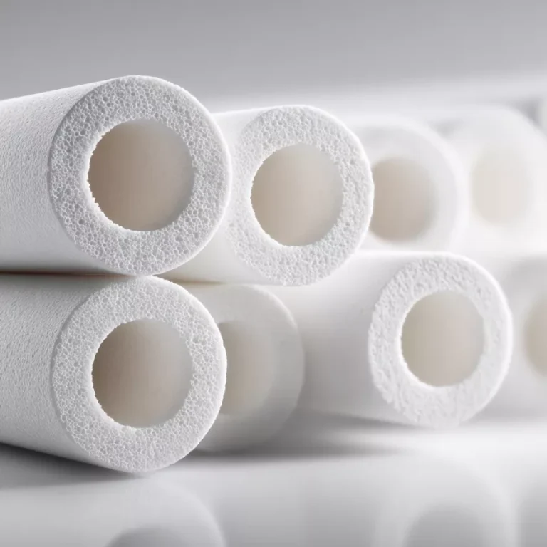
Type 4-Silicon Carbide Heating Element Tubes
| Sic Heating Element Type | OD / mm | Heating zone length / mm | Cold zone length / mm | Range of resistance / Ω | Purity |
| AT-THG-BC001 | 14 | 200 | 250 | 1.2-1.3 | 99% |
| AT-THG-BC002 | 14 | 250 | 250 | 1.5-3.0 | 99% |
| AT-THG-BC003 | 14 | 300 | 250 | 1.8-3.5 | 99% |
| AT-THG-BC004 | 14 | 400 | 350 | 2.3-4.7 | 99% |
| AT-THG-BC005 | 14 | 500 | 350 | 2.9-5.9 | 99% |
| AT-THG-BC006 | 16 | 200 | 200 | 0.9-1.9 | 99% |
| AT-THG-BC007 | 16 | 250 | 200 | 1.2-2.4 | 99% |
| AT-THG-BC008 | 16 | 300 | 300 | 1.4-2.8 | 99% |
| AT-THG-BC009 | 18 | 250 | 250 | 0.9-1.8 | 99% |
| AT-THG-BC010 | 18 | 300 | 350 | 1.1-2.2 | 99% |
| AT-THG-BC011 | 18 | 400 | 250 | 1.4-2.9 | 99% |
| AT-THG-BC012 | 18 | 500 | 350 | 1.8-3.6 | 99% |
| AT-THG-BC013 | 20 | 200 | 200 | 0.6-1.2 | 99% |
| AT-THG-BC014 | 20 | 250 | 250 | 0.7-1.4 | 99% |
| AT-THG-BC015 | 20 | 300 | 300 | 0.8-1.6 | 99% |
| AT-THG-BC016 | 20 | 400 | 350 | 1.1-2.2 | 99% |
| AT-THG-BC017 | 20 | 500 | 400 | 1.4-2.8 | 99% |
| AT-THG-BC018 | 20 | 600 | 350 | 1.5-3.0 | 99% |
| AT-THG-BC019 | 25 | 300 | 400 | 0.6-1.3 | 99% |
| AT-THG-BC020 | 25 | 400 | 400 | 0.8-1.7 | 99% |
| AT-THG-BC021 | 25 | 500 | 400 | 1.1-2.2 | 99% |
| AT-THG-BC022 | 25 | 600 | 500 | 1.3-2.6 | 99% |
| AT-THG-BC023 | 25 | 800 | 450 | 1.7-3.4 | 99% |
| AT-THG-BC024 | 25 | 900 | 400 | 1.9-3.8 | 99% |
| AT-THG-BC025 | 25 | 1000 | 500 | 2.2-4.5 | 99% |
| AT-THG-BC026 | 30 | 400 | 400 | 0.5-0.9 | 99% |
| AT-THG-BC027 | 30 | 500 | 400 | 0.6-1.2 | 99% |
| AT-THG-BC028 | 30 | 1000 | 500 | 1.1-2.2 | 99% |
| AT-THG-BC029 | 30 | 1200 | 500 | 1.3-2.6 | 99% |
| AT-THG-BC030 | 30 | 1300 | 500 | 1.4-2.9 | 99% |
| AT-THG-BC031 | 30 | 1500 | 250 | 1.6-3.4 | 99% |
| AT-THG-BC032 | 30 | 1500 | 300 | 1.6-3.4 | 99% |
| AT-THG-BC033 | 30 | 1500 | 600 | 1.6-3.4 | 99% |
| AT-THG-BC034 | 30 | 2000 | 650 | 2.2-4.4 | 99% |
| AT-THG-BC035 | 35 | 400 | 400 | 0.4-0.8 | 99% |
| AT-THG-BC036 | 35 | 500 | 400 | 0.5-1.0 | 99% |
| AT-THG-BC037 | 35 | 1000 | 500 | 1.0-2.0 | 99% |
| AT-THG-BC038 | 35 | 1200 | 500 | 1.1-2.2 | 99% |
| AT-THG-BC039 | 35 | 1500 | 500 | 1.4-2.8 | 99% |
| AT-THG-BC040 | 40 | 400 | 400 | 0.3-0.7 | 99% |
| AT-THG-BC041 | 40 | 1000 | 500 | 0.8-1.7 | 99% |
| AT-THG-BC042 | 40 | 1500 | 500 | 1.3-2.6 | 99% |
| AT-THG-BC043 | 40 | 2000 | 650 | 1.7-3.4 | 99% |
| AT-THG-BC044 | 40 | 2400 | 700 | 2.0-4.0 | 99% |
| AT-THG-BC045 | 40 | 2600 | 850 | 2.2-4.4 | 99% |
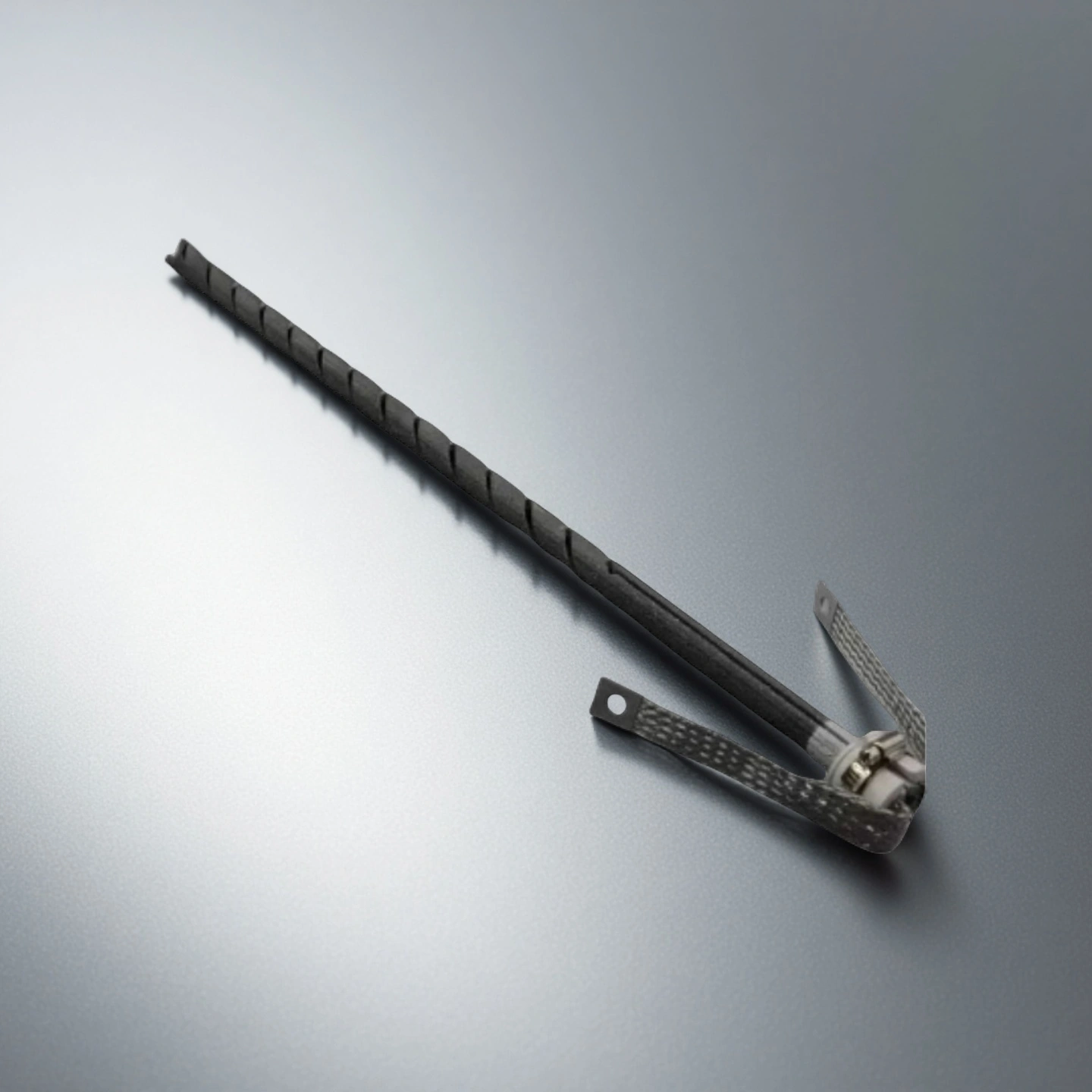
Type 5-Silicon Carbide Heating Element Type W

| Three Phase Type | Heat zone OD / mm | Heating zone length / mm | Cold zone Length / mm | center distance / mm | Bridge OD / mm | Overall length / mm | Purity |
| AT-THG-BF001 | 14 | 200 | 250 | 40 | 14 | 54 | 99% |
| AT-THG-BF002 | 14 | 250 | 300 | 50 | 14 | 64 | 99% |
| AT-THG-BF003 | 14 | 300 | 350 | 60 | 14 | 74 | 99% |
| AT-THG-BF004 | 16 | 200 | 250 | 40 | 16 | 56 | 99% |
| AT-THG-BF005 | 16 | 250 | 300 | 50 | 16 | 66 | 99% |
| AT-THG-BF006 | 16 | 300 | 350 | 60 | 16 | 76 | 99% |
| AT-THG-BF007 | 18 | 300 | 350 | 60 | 18 | 78 | 99% |
| AT-THG-BF008 | 18 | 400 | 400 | 70 | 18 | 88 | 99% |
| AT-THG-BF009 | 18 | 500 | 450 | 75 | 18 | 93 | 99% |
| AT-THG-BF010 | 20 | 250 | 300 | 50 | 20 | 70 | 99% |
| AT-THG-BF011 | 20 | 300 | 350 | 60 | 20 | 80 | 99% |
| AT-THG-BF012 | 20 | 400 | 400 | 70 | 20 | 90 | 99% |
| AT-THG-BF013 | 25 | 400 | 400 | 70 | 25 | 95 | 99% |
| AT-THG-BF014 | 25 | 500 | 450 | 75 | 25 | 100 | 99% |
| AT-THG-BF015 | 25 | 600 | 500 | 80 | 25 | 105 | 99% |
| AT-THG-BF016 | 30 | 600 | 400 | 70 | 30 | 100 | 99% |
| AT-THG-BF017 | 30 | 700 | 450 | 75 | 30 | 105 | 99% |
| AT-THG-BF018 | 30 | 800 | 500 | 80 | 30 | 110 | 99% |
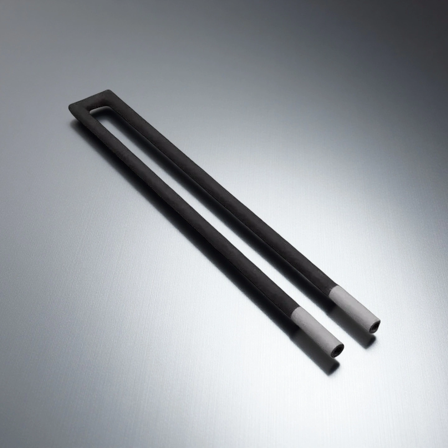
Type 6-Silicon Carbide Heating Element Type U

| U-type Heating Elements | Heating zone OD / mm | Heating zone Length / mm | Cold zone Length / mm | center distance / mm | Bridge OD / mm | Overall length / mm | Range of resistance / Ω | Purity |
| AT-THG-BU001 | 14 | 200 | 250 | 40 | 14 | 54 | 2.4-4.6 | 99% |
| AT-THG-BU002 | 14 | 250 | 300 | 50 | 14 | 64 | 3.0-6.0 | 99% |
| AT-THG-BU003 | 14 | 300 | 350 | 60 | 14 | 74 | 3.6-7.0 | 99% |
| AT-THG-BU004 | 16 | 200 | 250 | 40 | 16 | 56 | 1.4-2.8 | 99% |
| AT-THG-BU005 | 16 | 250 | 300 | 50 | 16 | 66 | 1.8-3.6 | 99% |
| AT-THG-BU006 | 16 | 300 | 350 | 60 | 16 | 76 | 2.0-5.0 | 99% |
| AT-THG-BU007 | 18 | 300 | 350 | 60 | 18 | 78 | 2.0-5.0 | 99% |
| AT-THG-BU008 | 18 | 400 | 400 | 70 | 18 | 88 | 2.8-5.8 | 99% |
| AT-THG-BU009 | 18 | 500 | 450 | 75 | 18 | 93 | 3.6-7.2 | 99% |
| AT-THG-BU010 | 20 | 250 | 300 | 50 | 20 | 70 | 1.8-3.6 | 99% |
| AT-THG-BU011 | 20 | 300 | 350 | 60 | 20 | 80 | 2.0-5.0 | 99% |
| AT-THG-BU012 | 20 | 400 | 400 | 70 | 20 | 90 | 2.8-5.8 | 99% |
| AT-THG-BU013 | 25 | 400 | 400 | 70 | 25 | 95 | 1.6-3.4 | 99% |
| AT-THG-BU014 | 25 | 500 | 450 | 75 | 25 | 100 | 2.2-4.4 | 99% |
| AT-THG-BU015 | 25 | 600 | 500 | 80 | 25 | 105 | 2.6-5.2 | 99% |
| AT-THG-BU016 | 30 | 600 | 400 | 70 | 30 | 100 | 1.4-2.8 | 99% |
| AT-THG-BU017 | 30 | 700 | 450 | 75 | 30 | 105 | 1.6-3.2 | 99% |
| AT-THG-BU018 | 30 | 800 | 500 | 80 | 30 | 110 | 1.8-3.6 | 99% |
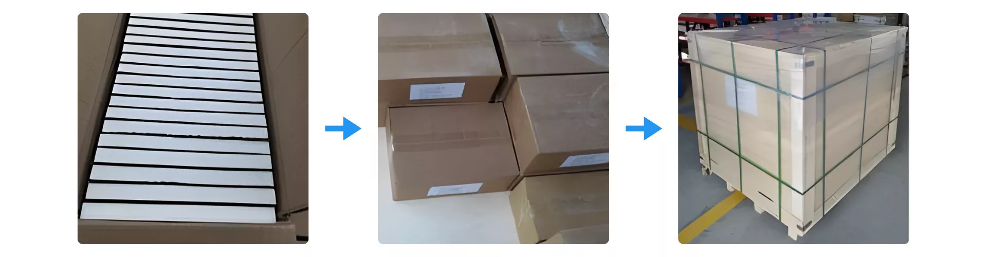
Packaging Method of Silicon Carbide Heating Tube
Silicon Carbide Heating Tube is individually protected with reinforced inner cartons to prevent vibration and surface abrasion during transit. Each batch is then consolidated into export-grade cardboard boxes with clear labeling for safe handling and identification. The boxed units are finally secured on fumigation-free pallets using strapping and film wrapping to ensure stable, damage-free delivery during international shipment.