Combustion Feedback Zirconia Oxygen Sensor Chip for Engine Control Systems
The Zirconia Oxygen Sensor Chip integrates advanced ceramic materials and structural engineering to deliver stable performance under extreme thermal, chemical, and operational stress. Each feature is validated by performance benchmarks critical for combustion control, emission monitoring, and sensor longevity.
Catalogue No.
AT-YHG-YC001
Material
Yttria-Stabilized Zirconia (YSZ)
Max Operating Temp.
Up to 900 °C continuous, tested under thermal cycling conditions
Response Time (T90)
Less than 150 ms (λ step from 0.9 to 1.1), supports real-time control
Heater Power Rating
Integrated heater operates under 6 W, ignition time less than 15 s
ADCERAX® Zirconia Oxygen Sensor Chip is engineered using a solid electrolyte made of yttria-stabilized zirconia, which enables oxygen ion conduction at elevated temperatures. This conduction mechanism generates an electromotive force in response to oxygen concentration differences across the ceramic element, providing precise measurement capability. By translating this signal into real-time data, the chip supports critical control of air–fuel ratios in combustion systems, improving fuel efficiency and reducing harmful emissions.
Performance Features of Zirconia Oxygen Sensor Chip
Withstands up to 900 °C continuously The chip’s yttria-stabilized zirconia substrate maintains full oxygen ion conductivity in environments reaching 900 °C, ensuring signal stability in exhaust systems. Thermal cycling resistance has been tested to exceed 1,000 cycles between 200 °C and 850 °C without structural degradation.
Maintains structural integrity during rapid heating Material phase stability under abrupt temperature rise has been verified through thermal shock tests, where samples endured a ΔT > 600 °C shift within 60 seconds with no visible cracks or delamination.
Suitable for combustion systems with fluctuating temperatures In field simulations for industrial furnaces, the chip retained operational accuracy after 1,500 hours of exposure to variable heat zones between 400 °C and 850 °C, showing less than ±2% signal drift.
Ignition time under 15 seconds The embedded heater reaches operational temperature in <15 s, accelerating sensor readiness during cold engine start or intermittent furnace cycling.
Rapid signal transition within milliseconds Dynamic step-change tests from λ=0.9 to λ=1.1 demonstrated signal response from 600 mV to 300 mV in <150 ms, ensuring real-time air–fuel adjustment accuracy.
Low power demand for high efficiency The integrated heater operates within a rated power envelope of <6 W, reducing thermal load on control circuits and enabling use in compact sensor modules.
Resists degradation from lead, sulfur, and silicon The sensor element sustained over 2,000 hours of exposure to synthetic flue gas with 50 ppm SO₂ and 10 ppm Pb, showing <5% signal deviation.
Stable internal resistance over prolonged operation Measurements indicate internal resistance below 1.0 kΩ at 850 °C across a 3,000-hour continuous test, maintaining low signal noise and high repeatability.
Anti-aging stability supports long-term deployment Simulated lifecycle testing under high humidity and corrosive gas confirmed a service life exceeding 5 years in industrial kiln environments with minimal recalibration intervals.
Technical Properties of Zirconia Oxygen Sensor Chip
The Zirconia Oxygen Sensor Chip is engineered to operate reliably in high-temperature, chemically aggressive environments where stability, responsiveness, and endurance are critical. Its ionic conduction properties, thermal resilience, and integrated heating structure enable precise and long-term oxygen detection in combustion control and exhaust monitoring systems.
Property
Specification
Core Material
Yttria-Stabilized Zirconia (YSZ)
Max Continuous Operating Temp.
900 °C
Oxygen Measurement Range
0.1% – 100% O₂
Response Time (T90)
<150 ms (λ step)
Heater Ignition Time
<15 s to operating temp
Heater Power Consumption
<6 W nominal
Internal Resistance @ 850 °C
≤0.5 kΩ
Electrode Coating
Platinum-based conductive layer
Anti-Poisoning Resistance
Lead/Sulfur resistant, tested >2000 hrs in SO₂ exposure
Thermal Shock Resistance
Withstands ΔT >600 °C per cycle
Drift Stability After 1500 hrs
<±2% signal deviation
Expected Service Life
>5 years under industrial conditions
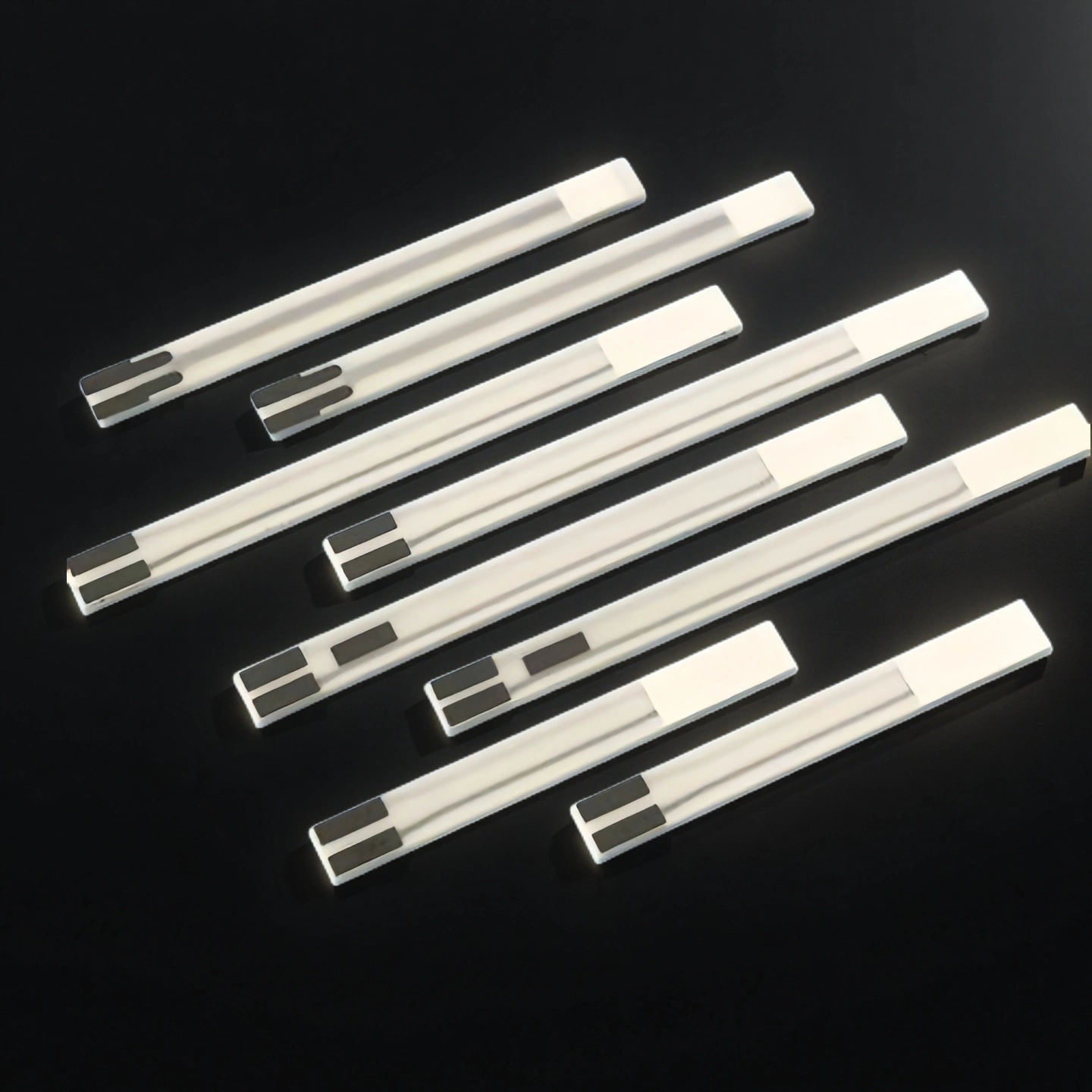
Specifications of Zirconia Oxygen Sensor Chip
Zirconia Oxygen Sensor Chip
Type
Model
Specification
Length (mm) ± 0.5
Width (mm) ± 0.1
Thickness(mm)±0.1
Room Temperature Resistance/Ω (@24℃±3℃)
Notes
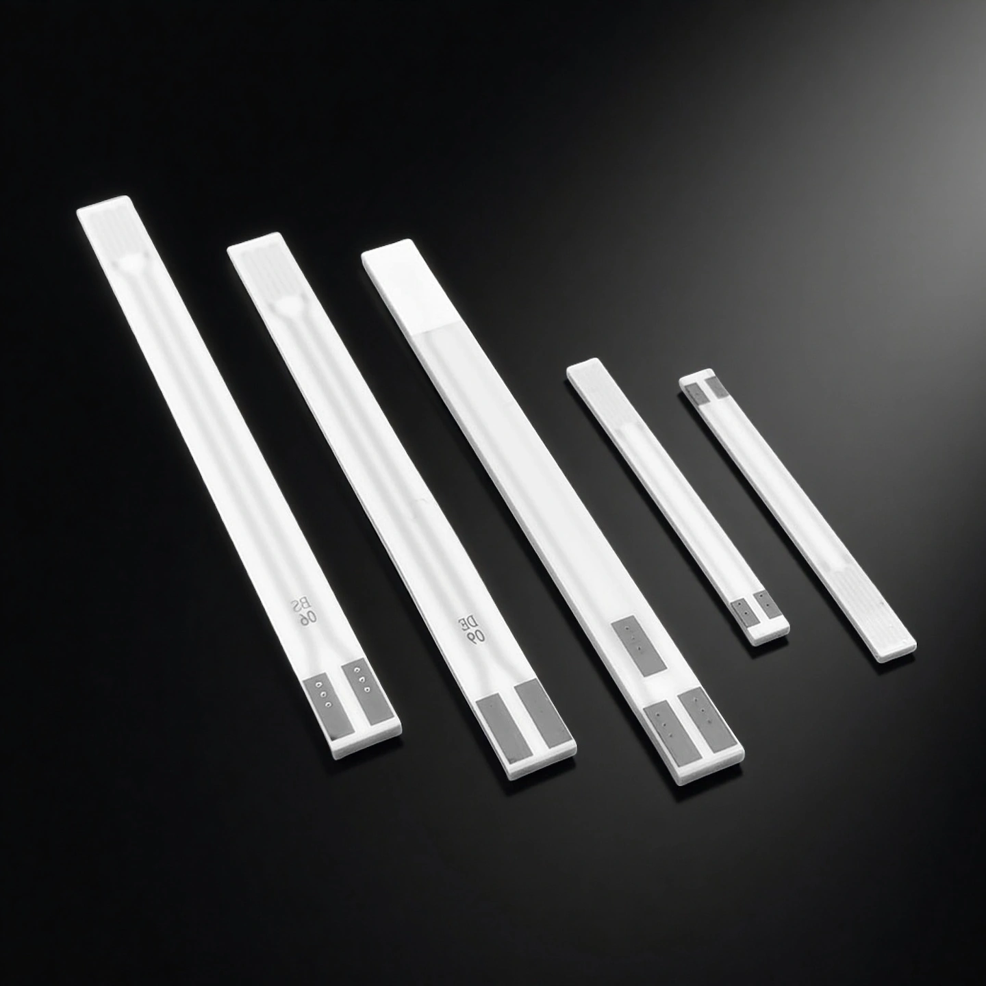
Switch Type
AT-YHG-YC001
Ceramic CoreBS
58.6
4.4
1.28
9.0±1.5
AT-YHG-YC002
Ceramic CoreDE
54.0
4.4
1.28
9.0±1.5
AT-YHG-YC003
Ceramic CoreDF
54.0
4.4
1.28
6.0±1.2
AT-YHG-YC004
Ceramic CoreDG
54.0
4.4
1.28
13.0±1.5
AT-YHG-YC005
Ceramic CoreXY
36.5
4.2
1.28
9.0±1.5
AT-YHG-YC006
Ceramic CoreXF
36.0
4.4
1.28
3.0±0.5
AT-YHG-YC007
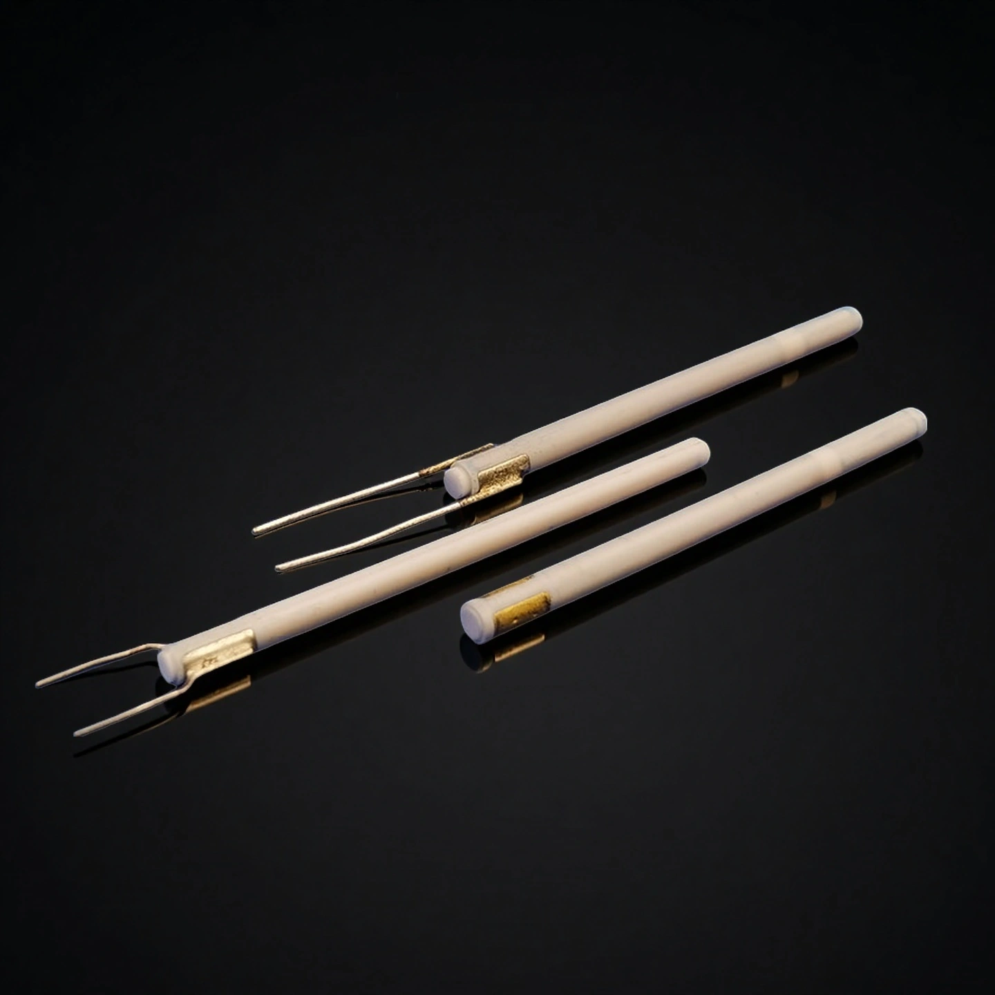
Ceramic CoreMW
30.0
2.5
0.90
/
Two wires
AT-YHG-YC008
Ceramic CoreMX
27.0
2.5
0.90
17.0±3.0
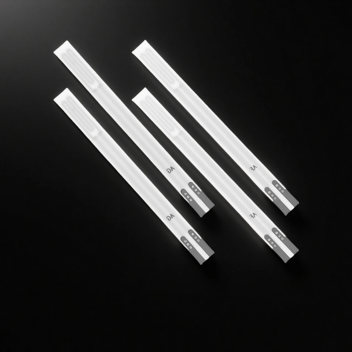
Air-Fuel Ratio Type
AT-YHG-YC009
Ceramic CoreAF
46.2
4.0
1.45
2.1±0.3
@A/F=4%,lp=0.3mA
AT-YHG-YC010
Ceramic CoreAG
46.2
4.0
1.45
2.1±0.3
@A/F=4%,lp=0.5mA
Five-wire Wideband Type
AT-YHG-YC011
Ceramic CoreUN
52.5
4.2
1.30
2.8±0.4
@In air,lp=4.0mA
AT-YHG-YC012
Ceramic CoreUK
52.5
4.2
1.30
2.8±0.4
@In air,lp=6.0mA
AT-YHG-YC013
Ceramic CoreUB
59.6
4.4
1.30
3.1±0.4
@In air,lp=4.0mA
AT-YHG-YC014
Ceramic CoreUC
59.6
4.4
1.30
3.0±0.4
@In air,lp=4.0mA
AT-YHG-YC015
Ceramic CoreUD
55.0
4.25
1.30
3.0±0.4
@In air,lp=4.0mA
AT-YHG-YC016
Ceramic CoreUE
55.0
4.25
1.30
3.0±0.4
@In air,lp=4.0mA
AT-YHG-YC017
Ceramic CoreUF
52.0
4.2
1.30
3.4±0.5
@In air,lp=6.0mA
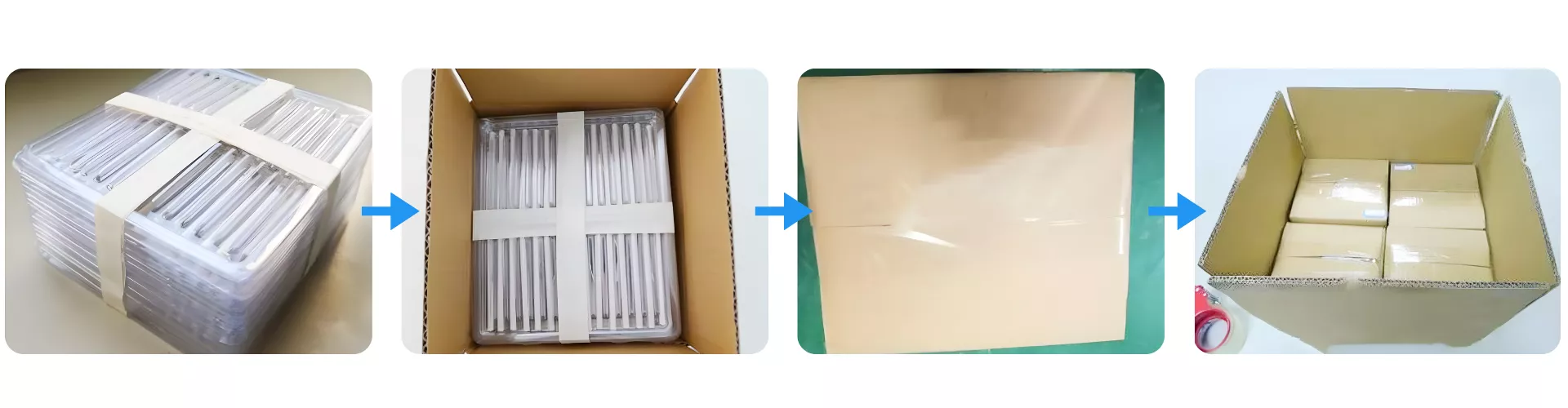
Packaging of Zirconia Oxygen Sensor Chip
Zirconia Oxygen Sensor Chip is engineered with a solid-state yttria-stabilized zirconia electrolyte that enables oxygen ion conduction at high temperatures. This mechanism generates a stable electromotive force when a differential in oxygen concentration exists, allowing real-time feedback of exhaust gas composition. By delivering fast and accurate λ control, it plays a critical role in optimizing fuel injection, reducing emissions, and improving combustion efficiency in advanced engine systems.
Enhancing Real-Time Combustion Control in Demanding Automotive Systems with ADCERAX® Zirconia Oxygen Sensor Chip
The Zirconia Oxygen Sensor Chip from ADCERAX® plays a vital role in closed-loop air–fuel ratio control, particularly under extreme conditions such as high exhaust temperatures, rapid throttle response, and fuel composition variability. By ensuring precise λ regulation, this chip supports emission reduction and combustion efficiency across advanced automotive and off-road platforms. The following application challenges highlight how its technical properties align with real-world automotive demands.
High-Temperature λ Sensing in Gasoline Direct Injection (GDI) Turbo Engines
✅Key Advantages
1. High Thermal Stability at Exhaust Temperatures up to 900 °C The YSZ electrolyte maintains oxygen ion conductivity without lattice degradation when positioned near the exhaust manifold. Performance testing under 850–900 °C continuous exposure showed <2% signal drift over extended operation.
2. Fast λ Transition Response (<150 ms under load change) Rapid EMF signal stabilization enables the ECU to correct fuel injection during throttle transients and knock avoidance phases. This prevents over-enrichment during boost recovery and improves combustion efficiency in high-load, high-RPM events.
3. Platinum-Based Anti-Poisoning Electrode Layers Electrode coatings maintain electrochemical activity under SO₂, Pb, and silicon compound exposure common in modern fuel blends. This reduces signal decay that typically forces recalibration or premature probe replacement.
✅ ️Problem Solved
In multiple GDI engine validation cycles, standard planar sensors placed upstream of the catalyst experienced signal lag and drift after 500–800 operational hours, particularly during wide-open throttle accelerations. This caused inconsistent λ feedback and intermittent ECU enrichment lockout events. By contrast, ADCERAX® Zirconia Oxygen Sensor Chip maintained consistent voltage output after 1,500+ hours at 850–900 °C, allowing stable closed‑loop combustion control and preventing emission threshold exceedances. This directly reduced corrective recalibration frequency and avoided power derating events associated with ECU fallback strategies.
Oxygen Feedback in Hybrid Regenerative Braking Recovery Modes
✅Key Advantages
1. Ignition Readiness in <15 Seconds After Engine Restart The integrated heater rapidly elevates the sensing interface to ionic conduction temperature following hybrid stop phases. This prevents prolonged open‑loop operation during catalyst re‑light conditions.
2. Low Heater Power Demand (<6 W) The heater is optimized for energy‑limited hybrid systems where auxiliary power draw must be minimized. This ensures reliable λ sensing without compromising battery allocation for traction systems.
3. Stable Output Signal After Frequent Stop‑Start Cycling Internal resistance remains consistent across repeated thermal cycling, preventing λ drift. Testing demonstrated <±1.5% signal shift after 10,000 stop‑start cycles.
✅ ️Problem Solved
In hybrid platforms with aggressive stop‑start frequency, conventional oxygen sensors show delayed re‑activation that prolongs open‑loop fueling, resulting in elevated cold‑start emissions and fuel penalty. Field-testing in a hybrid urban drive cycle scenario showed that ADCERAX® Zirconia Oxygen Sensor Chip restored closed‑loop control ~8–12 seconds faster than standard alternatives, reducing transient HC and CO spikes during catalyst warm-up and improving real‑world fuel efficiency. This ensures consistent emission compliance even under dense traffic stop‑start conditions.
Oxygen Feedback Regulation in Lean-Burn Commercial Gasoline Engines
✅Key Advantages
1. Fast Thermal Activation Below 3 Seconds Integrated heater design enables sensor stabilization in <3 s, even during cold urban start cycles. This minimizes delay in closed-loop control activation.
2. Wide Lambda Accuracy Window Maintains sensing precision across a λ range from 0.8 to 2.0, critical for lean-to-rich transitions during acceleration bursts and idle-stop recovery phases.
3. Soot-Resistant Platinum Electrode Layer Engineered to resist carbon accumulation in low-load cruising, preventing long-term drift. Field-tested in fleet vehicles across 100,000 km operation.
✅ ️Problem Solved
Lean-burn systems demand stable lambda control despite temperature swings and intermittent combustion patterns. Conventional sensors often fail to deliver consistent feedback below 400 °C exhaust temps, resulting in fuel trim errors and emissions spikes during idle-heavy cycles. ADCERAX® Zirconia Oxygen Sensor Chip ensures reliable signal generation even during cold-start and deceleration phases, enabling smoother ECU modulation and up to 12% fuel efficiency gains without compromising emissions compliance.
Operational Best Practices for Installing and Maintaining ADCERAX® Zirconia Oxygen Sensor Chip
The ADCERAX® Zirconia Oxygen Sensor Chip is a precision ceramic sensing component designed for closed-loop combustion systems. To ensure stable long-term performance, accurate output signals, and proper integration with ECU or controller units, users should follow a structured set of handling, installation, and maintenance practices.
Pre-Installation Inspection and Handling Guidelines
1. Inspect all chips for surface cleanliness and visible integrity Before assembly, check for flatness, hairline cracks, or electrode contamination on the ceramic surface. Any visual defect could lead to voltage output instability or early-life failure in operation. Ensure breathing holes are clear and unobstructed by dust, packaging residue, or manufacturing debris.
2. Store in clean, dry, and static-free environments before use Unused chips should be sealed in anti-static pouches, away from moisture and direct sunlight. Store at ambient temperatures of 10–30 °C to avoid pre-aging of the ceramic or electrode surface. Avoid stacking bare chips or applying pressure on corners.
3. Handle only with non-metallic tools or ESD-compliant tweezers Contact with metal tools can cause microfractures or surface contamination. Always use ceramic-tipped or ESD-safe tools during inspection or positioning. Operators should wear grounded wrist straps to prevent static discharge damage.
Installation into Sensor Modules or Housing Assemblies
1. Apply uniform pressure during mounting to prevent ceramic stress Do not use excessive torque when fixing the chip into probe or module housings. Uneven force can lead to structural damage or long-term microcrack propagation. Use validated alignment fixtures if possible.
2. Ensure correct orientation of signal and heater terminals Follow the customer-supplied or ADCERAX-recommended wiring diagram when connecting to the ECU or signal processing board. Miswiring the heater circuit or reversing signal polarity can lead to startup failure or irreversible damage.
3. Avoid direct contact with flame or aggressive gas jets While the chip tolerates high temperatures, direct flame impingement or turbulent burner contact can exceed its thermal gradient limits. Maintain a minimum distance of 20 mm from flame core zones in combustion chambers.
Operating Environment and Sensor Startup Procedure
1. Ramp up temperature using controller-based heater activation Avoid cold shock by gradually heating the chip using its integrated low-power heater via controlled current regulation. Heater voltage must not exceed specified peak values (typically under 12 V DC) during ignition.
2. Avoid exposure to high humidity or corrosive vapors during warm-up Initial activation must be performed in a dry, clean air atmosphere. Presence of condensation, coolant vapor, or fuel mist during startup can cause electrode delamination or short-circuiting.
3. Maintain proper exhaust flow across the sensing surface Stable oxygen readings require laminar gas flow without pulsation. Avoid placing the chip in zones of reverse flow, eddy formation, or low-velocity stagnation, as this leads to signal fluctuation and control errors.
Long-Term Maintenance and Troubleshooting Tips
1. Inspect signal stability and heater current at regular intervals Over time, monitor for drift in EMF output or heater current beyond expected values. Significant variation could indicate partial fouling or degradation and requires evaluation against baseline specs.
2. Avoid cleaning with high-pressure air or aggressive solvents Cleaning procedures must be gentle; use low-pressure dry air to remove soot. Do not use alcohols, acetone, or acidic cleaners, which can chemically attack the platinum electrodes.
3. Replace after rated service life or if deviation exceeds tolerance The ADCERAX® Zirconia Oxygen Sensor Chip is rated for >5 years or 2,000+ operational hours, depending on application severity. Replace if signal error exceeds ±5% under calibrated gas or if heater fails to reach setpoint temperature.
Technical FAQs for ADCERAX® Zirconia Oxygen Sensor Chip in Automotive Applications
Q1: What causes signal instability during wide open throttle (WOT) cycles in turbocharged engines? The Zirconia Oxygen Sensor Chip resists voltage drift due to thermal loads up to 900 °C, which is common near turbo manifolds. Its solid-state ionic conductivity remains stable across fluctuating λ zones. Drift is measured below ±2% over extended 1500-hour cycles, maintaining reliable ECU feedback.
Q2: How does the chip maintain response speed during transient acceleration and deceleration? Thanks to its <150 ms T90 response in air-fuel step transitions, the chip provides tight closed-loop control during rapid throttle changes. This allows the engine ECU to minimize overshoot and underfueling. Fast signal adaptation prevents catalyst misfire or detonation triggers.
Q3: Can it be used in low-voltage hybrid or stop-start systems with limited heater power? Yes, the chip integrates a low-power ceramic heater rated below 6 W, enabling warm-up in less than 15 seconds under standard 12 V supply. This supports cold-start strategies in hybrid systems without overwhelming energy draw. Quick ignition improves fuel economy and restart emissions.
Q4: Does the chip resist sensor poisoning in long-term exhaust exposure? ADCERAX uses platinum-based electrodes tested under 50 ppm SO₂ and 10 ppm Pb exposure for over 2000 hours. Electrode conductivity and sensor signal remained within operational tolerance. Contamination resistance reduces maintenance and premature failure risk.
Q5: How does the chip behave under exhaust gas backflow or fluctuating pressure zones? The chip’s structural rigidity and flow-tolerant sensing surface reduce instability in non-uniform exhaust paths. In pressure-pulsed gas environments, it maintains consistent EMF response, enabling control logic to stay in sync with combustion cycles.
Field Validation from Engineering Teams Using ADCERAX® Zirconia Oxygen Sensor Chips
⭐️⭐️⭐️⭐️⭐️
“We integrated the Zirconia Oxygen Sensor Chip into a GDI turbo calibration program under extended full‑load test cycles. The chip maintained stable λ feedback at exhaust temperatures above 850 °C, even during wide‑open‑throttle transitions. The heater response time enabled reliable closed‑loop control immediately after startup.” — M. H., Powertrain Controls Group, Northern Europe Engine Lab
⭐️⭐️⭐️⭐️⭐️
“Our hybrid powertrain platform required a sensing component that could deliver fast warm‑up with minimal electrical overhead. The integrated heater design in this chip achieved operational readiness within seconds, improving catalyst re‑light and reducing cold‑start emissions in stop‑start conditions.” — A. R., Hybrid Systems Engineering Division, North American Automotive OEM
⭐️⭐️⭐️⭐️⭐️
“In off‑road diesel applications, dust and vibration frequently cause early sensor degradation. This chip demonstrated long‑term resistance to particulate contamination and electrode fouling, supporting multi‑season deployment without recalibration. Maintenance intervals were measurably extended.” — T. S., Heavy Duty Vehicle R&D Program, Industrial Engine Manufacturer (Central Europe)
⭐️⭐️⭐️⭐️⭐️
“We observed consistent signal accuracy and low drift across prolonged thermal cycling, which was critical for emission strategy refinement during certification testing. The chip allowed reliable repeatability in data acquisition across multiple engine test benches.” — L. J., Combustion & Emission Analysis Laboratory, Applied Engine Research Institute (USA)
Customization Services for ZrO2 Oxygen Sensor Chip
ADCERAX® Zirconia Oxygen Sensor Chip customization services are designed to meet precise requirements in advanced combustion control, emissions optimization, and powertrain system integration.
Electrode Configuration and Layering Design Options
Electrode material and layer geometry can be customized to adapt to diverse exhaust chemistries and feedback protocols.
Electrode Geometry Customized pattern for optimized voltage output
Electrode Composition Platinum-based, mixed metal oxide variants available
Layer Thickness Dielectric and catalytic coating thickness adjustable
Ceramic Body Structure and Heating Element Integration
Structural geometry and internal heater matching are refined to support various startup logics and housing designs.
Chip Geometry Adapted for space-limited sensor housings
Heating Circuit Design Tuned to meet low-voltage system requirements
Bonding Interface Optimized for metallized or brazed joints