Aluminum nitride ceramic packaging shell is a precision-machined structural enclosure made from high-thermal-conductivity aluminum nitride (AlN) ceramic, designed to serve as the mechanical, thermal and electrical foundation for high-power electronic and optoelectronic devices. It provides a rigid housing, a low-resistance heat-dissipation path, and a high-insulation barrier within a single monolithic ceramic body.
AIN Ceramic Packaging Shell Benefits
-
Thermal path designed into the shell
The aluminum nitride ceramic packaging shell uses high-conductivity AlN so that heat spreads efficiently from the die region into the base and mounting interface, reducing junction temperature at power densities above 50–100 W/cm². -
CTE matching to Si and SiC devices
The coefficient of thermal expansion of the AlN shell is close to Si and SiC, which reduces thermo-mechanical stress on solder and sintered joints during thermal cycling and extends module lifetime. -
Controlled cavity and wall geometry
Cavity depth, wall thickness and step features are machined to tight tolerances to support automated pick-and-place, wire bonding and lid sealing, with typical dimensional tolerances down to ±0.05–0.10 mm on critical features. -
Support for complex metallization layouts
The surface of the AlN ceramic package can be prepared for Mo/Mn, W-based or sputtered metal systems, enabling fine-pitch pads, isolated lands and ground planes for RF and power layouts. -
Suitable for hermetic or near-hermetic sealing
The dense aluminum nitride ceramic packaging shell structure and flat sealing surfaces support solder-sealed metal lids or glass-to-metal transitions for low leak rates in demanding environments.
Aluminum Nitride Package Shell Properties
| Property Content | Property | Unit | ALN-170 | ALN-200 | ALN-230 |
| Basic Properties | Color | gray | light yellow | light yellow | |
| Density | g/cm³ | 3.2-3.3 | 3.2-3.3 | 3.2-3.3 | |
| Surface Roughness | μm | 0.2-0.75 | 0.2-0.75 | 0.2-0.8 | |
| Camber | length ‰ | ≤3‰ | ≤3‰ | ≤3‰ | |
| Hardness | HV | 1100 | 1100 | 1100 | |
| Thermal Properties | Max Operating Temperature | °C | 1100 | 1100 | 1100 |
| Thermal Conductivity | W/m·K | 170-190 | 190-220 | 220-230 | |
| Coefficient of Thermal Expansion | 10⁻⁶/K(20-400°c) | 4-5 | 4-5 | 4-5 | |
| Coefficient of Thermal Expansion | 10⁻⁶/K(400-800°c) | 5-6 | 5-6 | 5-6 | |
| Mechanical Properties | Flexural Strength | MPa | 300-400 | 350-450 | 400-500 |
| Tensile Strength | MPa | 200-300 | 250-350 | 280-380 | |
| Compressive Strength | MPa | 2000-3000 | 2200-3200 | 2500-3500 | |
| Electrical properties | Dielectric Constant | at 1MHz | 8-9 | 8-9 | 8-9 |
| Dielectric strength | KV/mm | ≥15 | ≥15 | ≥15 | |
| Volume resistivity | 20℃ Ω.cm | ≥1014 | ≥1014 | ≥1014 |
Aluminium Nitride Ceramic Packaging Shell Specifications
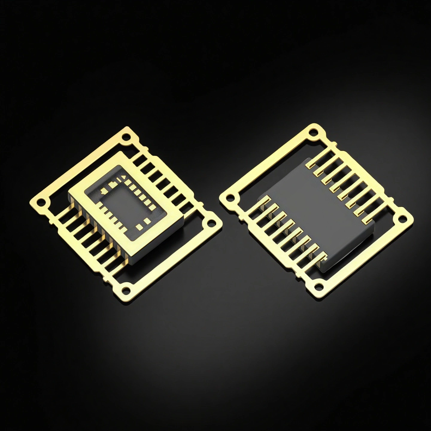
Type 1: CDIP Ceramic Dual-in-line Shell
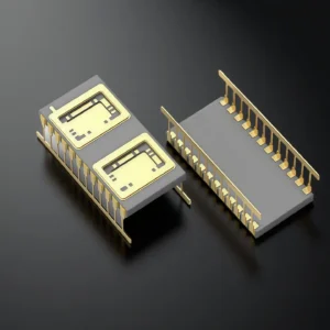
| CDIP Ceramic Dual-in-line Shell | ||||||
| Model | Number of Leads | Lead Pitch | Core Cavity Size | Ceramic Package Size | Sealing Method | With/Without Heat Sink |
| AT-DIP04B | 4 | 2.54 | 5.4*3.2 | 7.4*5.2 | Flat Seal | No |
| AT-DIP04C | 4 | 2.54 | 5.3*2.65 | 7.4*5.1 | Flat Seal | No |
| AT-DIP04D | 4 | 2.54 | 5.4*3.2 | 7.4*5.2 | Flat Seal | No |
| AT-DIP04S2 | 4 | 2.54 | 5.0*2.6 | 7.3*5 | Flat Seal | No |
| AT-DIP06B | 6 | 2.54 | 6.6*5.4 | 8.4*7.4 | Flat Seal | No |
| AT-DIP06C | 6 | 2.54 | 6.6*5.4 | 8.51*7.49 | Flat Seal | No |
| AT-DIP06D | 6 | 2.54 | 6.6*5.4 | 8.4*7.4 | Flat Seal | No |
| AT-DIP06E | 6 | 2.54 | 5.16*4 | 9*7.4 | Flat Seal | No |
| AT-DIP06S3 | 6 | 2.54 | 5.2*4.2 | 9.3*7.4 | Flat Seal | No |
| AT-DIP08A | 8 | 2.54 | 7.7*5.4 | 9.7*7.4 | Flat Seal | No |
| AT-DIP08AL | 8 | 2.54 | 10.08*7.37 | 8*5.72 | Flat Seal | No |
| AT-DIP08M | 8 | 2.54 | 17.1*6.6 | 19.46*9.91 | Flat Seal | No |
| AT-DIP08S2 | 8 | 2.54 | 5.72*5.21 | 10.28*7.37 | Flat Seal | No |
| AT-DIP12 | 12 | 2.54 | 5.6*3.8 | 15.24*7.37 | Flat Seal | No |
| AT-DIP14 | 14 | 2.54 | 5.6*3.8 | 17.9*7.5 | Flat Seal | No |
| AT-DIP16 | 16 | 2.54 | 5.6*4.32 | 20.32*7.37 | Flat Seal | No |
| AT-DIP16A | 16 | 2.54 | 5.59*4.19 | 20.32*7.42 | Flat Seal | No |
| AT-DIP16B | 16 | 2.54 | 5.6*3.8 | 20.32*7.5 | Flat Seal | No |
| AT-DIP16C | 16 | 2.54 | 5.4*4.5 | 23.6*7.4 | Flat Seal | No |
| AT-DIP16S2 | 16 | 2.54 | 18.2*4.9 | 20.6*7.37 | Flat Seal | No |
| AT-DIP20A | 20 | 2.54 | 5.6*3.8 | 25.14*7.37 | Flat Seal | No |
| AT-DIP24 | 24 | 2.54 | 5.75*3.8 | 30.48*7.49 | Flat Seal | No |
| AT-DIP28A | 28 | 2.54 | 5.6*4.2 | 40*25.1 | Flat Seal | No |
| AT-DIP32 | 32 | 2.54 | 10*6.2 | 40.64*9.91 | Flat Seal | No |
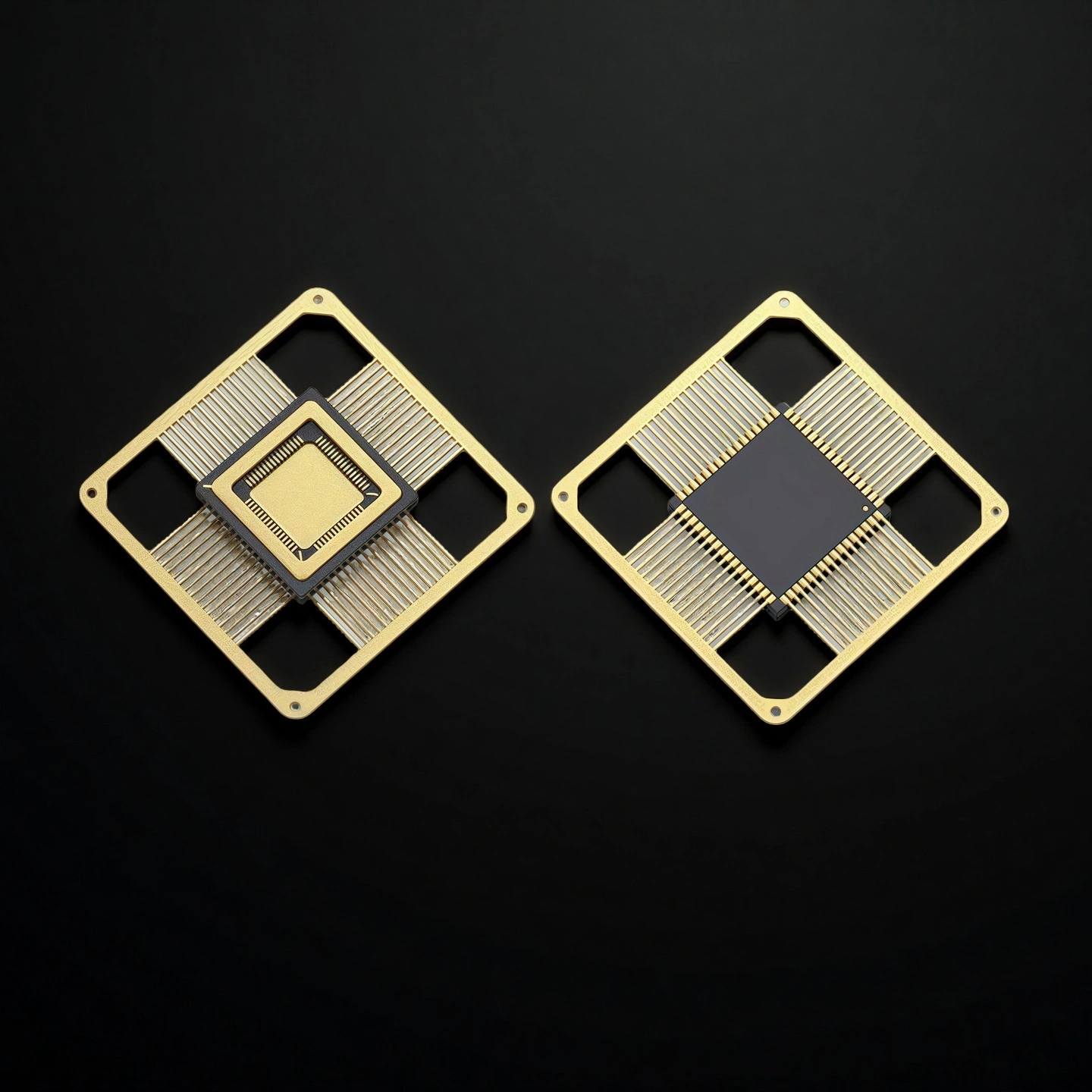
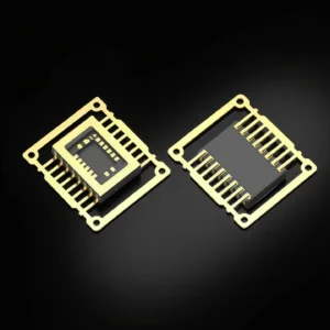
Type 2: CQFP Ceramic Quad Flat Shell

| CQFP Ceramic Quad Flat Shell | ||||||
| Item No. | Number of Leads | Lead Pitch | Core Cavity Size | Ceramic Package Size | Sealing Method | With/Without Heat Sink |
| AT-CQFP24A | 24 | 0.65 | 3.3*3.3 | 6.6*6.8 | AuSn (Gold-Tin) | Yes |
| AT-CQFP28 | 28 | 1.27 | 7.6*7.6 | 12*12 | AuSn (Gold-Tin) | No |
| AT-CQFP28B | 28 | 1.27 | 5.5*5.5 | 11.43*11.43 | Flat Seal | Yes |
| AT-CQFP28D | 28 | 0.8 | 4.2*4.2 | 9*9 | AuSn (Gold-Tin) | Yes |
| AT-CQFP28E | 28 | 0.8 | 4.5*4.5 | 7*7 | AuSn (Gold-Tin) | Yes |
| AT-CQFP28F | 28 | 0.8 | 4.2*4.2 | 9*9 | AuSn (Gold-Tin) | Yes |
| AT-CQFP40B | 40 | 1.27 | 4.8*4.8 | 14.6*14.6 | AuSn (Gold-Tin) | No |
| AT-CQFP40D | 40 | 0.5 | 4.6*4.6 | 11*11 | AuSn (Gold-Tin) | Yes |
| AT-CQFP44 | 44 | 0.8 | 6.1*6.1 | 10*10 | AuSn (Gold-Tin) | No |
| AT-CQFP44B | 44 | 0.8 | 6.4*6.4 | 10*10 | AuSn (Gold-Tin) | No |
| AT-CQFP44C | 44 | 0.8 | 6.9*6.9 | 10*10 | AuSn (Gold-Tin) | No |
| AT-CQFP44E | 44 | 0.8 | 5.13*5.13 | 10.6*10.6 | AuSn (Gold-Tin) | No |
| AT-CQFP44F | 44 | 1.27 | 8.1*8.1 | 16.51*16.51 | AuSn (Gold-Tin) | No |
| AT-CQFP48A | 48 | 0.5 | 4.2*4.2 | 8.5*8.5 | AuSn (Gold-Tin) | No |
| AT-CQFP48B | 48 | 1 | 6*6 | 14.22*14.22 | AuSn (Gold-Tin) | No |
| AT-CQFP48C | 48 | 1 | 8.9*8.9 | 14.22*14.22 | AuSn (Gold-Tin) | No |
| AT-CQFP48D | 48 | 1 | 8.7*8.7 | 14.22*14.22 | AuSn (Gold-Tin) | No |
| AT-CQFP64A | 64 | 0.8 | 5*5 | 14*5*14.5 | AuSn (Gold-Tin) | No |
| AT-CQFP64B | 64 | 0.8 | 6.4*6.4 | 14.6*14.6 | AuSn (Gold-Tin) | No |
| AT-CQFP64C | 64 | 1 | 5*5 | 18.4*18.4 | AuSn (Gold-Tin) | No |
| AT-CQFP64D | 64 | 0.8 | 8*8 | 14.6*14.6 | AuSn (Gold-Tin) | No |
| AT-CQFP64E | 64 | 1 | 9.2*9.2 | 18.4*18.4 | AuSn (Gold-Tin) | No |
| AT-CQFP64P | 64 | 0.5 | 7*7 | 11*11 | AuSn (Gold-Tin) | No |
| AT-CQFP80A | 80 | 0.5 | 7.8*7.8 | 12.2*12.2 | AuSn (Gold-Tin) | No |
| AT-CQFP84 | 84 | 1.27 | 15.1*15.1 | 29.3*29.3 | AuSn (Gold-Tin) | No |
| AT-CQFP100B | 100 | 0.65 | 7.6*7.6 | 22*16 | AuSn (Gold-Tin) | No |
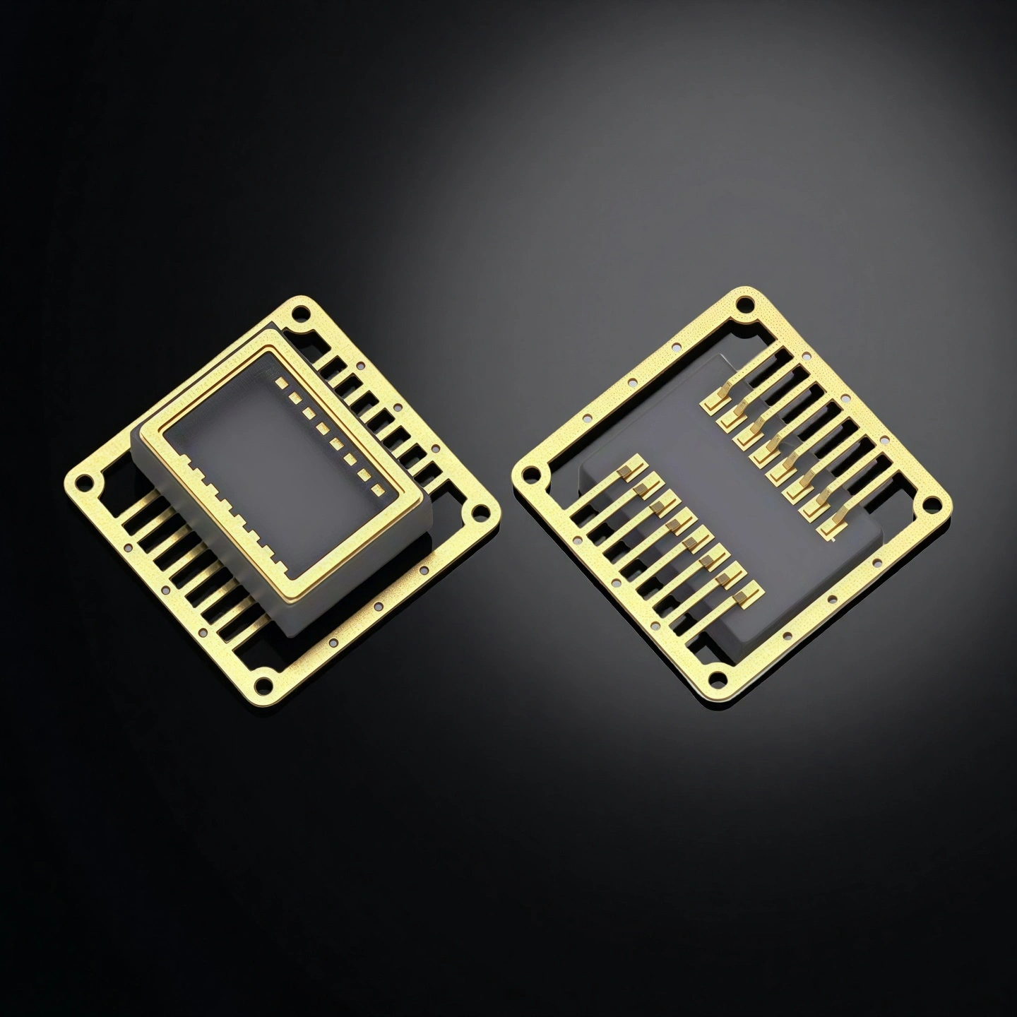
Type 3: CFP Ceramic Flat Housing
| CFP Ceramic Flat Housing | ||||||
| Item No. | Number of Leads | Lead Pitch | Core Cavity Size | Ceramic Package Size | Sealing Method | With/Without Heat Sink |
| AT-FP04X2 | 4 | 1.27 | 3.4*1.6 | 5*3.2 | Flat Seal | No |
| AT-FP08M | 8 | 1.27 | 2.5*1.8 | 5.6*5.2 | Flat Seal | No |
| AT-FP08N | 8 | 1.27 | 3.4*2.2 | 6.6*4.2 | Flat Seal | No |
| AT-FP10K | 10 | 1.27 | 4.5*3 | 6.35*6.35 | Flat Seal | No |
| AT-FP14H | 14 | 1.27 | 3.4*2.4 | 9*4.4 | Flat Seal | No |
| AT-FP16F | 16 | 1.27 | 8.1*5.1 | 10.4*7.4 | Flat Seal | No |
| AT-FP16P | 16 | 1.27 | 5*2.5 | 9.9*6.35 | Flat Seal | No |
| AT-FP20D | 20 | 1.27 | 5.6*4.3 | 10.1*7.5 | Flat Seal | No |
| AT-FP28 | 28 | 1.27 | 6.3*5.3 | 17.75*12.45 | Flat Seal | No |
| AT-FP36 | 36 | 1.27 | 19.67*9.66 | 23.37*14.73 | Flat Seal | No |
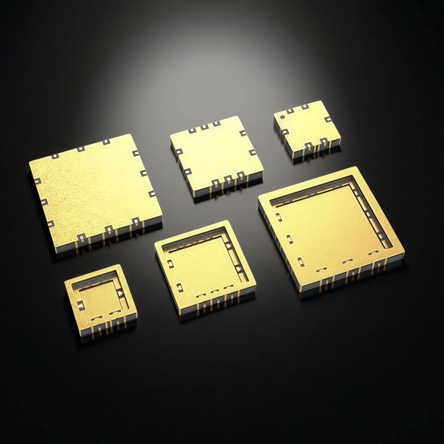
Type 4: CQFN Ceramic Four-sided Flat Pinless Packaging Shell

| CQFN Ceramic Four-sided Flat Pinless Packaging Shell | ||||||
| Product Name | Number of Leads | Lead Pitch | Core Cavity Size | Ceramic Package Size | Sealing Method | With/Without Heat Sink |
| AT-CQFN12 | 12 | 0.5 | SQ1.4 | SQ3 | AuSn (Gold-Tin) | No |
| AT-CQFN12A | 12 | 1.27 | SQ1.5 | SQ5 | AuSn (Gold-Tin) | No |
| AT-CQFN12B | 12 | 1 | SQ4.25 | SQ7.65 | AuSn (Gold-Tin) | No |
| AT-CQFN12C | 12 | 1 | 2.2*1.8 | SQ7.65 | AuSn (Gold-Tin) | No |
| AT-CQFN16 | 16 | 0.5 | SQ2.2 | SQ4 | AuSn (Gold-Tin) | No |
| AT-CQFN16A | 16 | 0.65 | SQ1.4 | SQ4 | AuSn (Gold-Tin) | No |
| AT-CQFN16B | 16 | 0.5 | SQ1.4 | SQ3 | AuSn (Gold-Tin) | No |
| AT-CQFN16C | 16 | 1.27 | SQ4.5 | SQ7 | AuSn (Gold-Tin) | No |
| AT-CQFN16D | 16 | 1.27 | SQ2.4 | SQ4.6 | AuSn (Gold-Tin) | No |
| AT-CQFN16F | 16 | 0.5 | SQ2.4 | SQ4.6 | AuSn (Gold-Tin) | No |
| AT-CQFN20 | 20 | 0.5 | SQ2.2 | SQ4 | AuSn (Gold-Tin) | No |
| AT-CQFN20B | 20 | 0.5 | SQ2.2 | SQ4 | AuSn (Gold-Tin) | No |
| AT-CQFN20D | 20 | 0.5 | SQ2 | SQ4 | AuSn (Gold-Tin) | No |
| AT-CQFN20E | 20 | 0.5 | SQ1.7 | SQ4 | AuSn (Gold-Tin) | No |
| AT-CQFN20P | 20 | 1.5 | SQ8.4 | SQ10 | AuSn (Gold-Tin) | No |
| AT-CQFN24 | 24 | 0.5 | SQ2.62 | SQ4 | AuSn (Gold-Tin) | No |
| AT-CQFN24A | 24 | 0.5 | SQ2.62 | SQ4 | AuSn (Gold-Tin) | No |
| AT-CQFN24B | 24 | 0.5 | SQ2.7 | SQ4 | AuSn (Gold-Tin) | No |
| AT-CQFN24C | 24 | 0.5 | SQ2.7 | SQ4 | AuSn (Gold-Tin) | No |
| AT-CQFN24D | 24 | 0.5 | SQ2.2 | SQ4 | AuSn (Gold-Tin) | No |
| AT-CQFN24E | 24 | 0.5 | SQ2.5 | SQ4 | AuSn (Gold-Tin) | No |
| AT-CQFN32 | 32 | 0.5 | SQ3.3 | SQ5 | AuSn (Gold-Tin) | No |
| AT-CQFN32G | 24 | 0.5 | SQ5 | SQ7 | AuSn (Gold-Tin) | No |
| AT-CQFN32L | 32 | 0.5 | SQ4.4 | SQ7 | AuSn (Gold-Tin) | No |
| AT-CQFN40 | 40 | 0.5 | SQ4.5 | SQ6 | AuSn (Gold-Tin) | No |
| AT-CQFN40A | 40 | 0.5 | SQ3 | SQ6 | AuSn (Gold-Tin) | No |
Type 5: CSOP Ceramic Small-profile Shell

| CSOP Ceramic Small-profile Shell | ||||||
| Item No. | Number of Leads | Lead Pitch | Core Cavity Size | Ceramic Package Size | Sealing Method | With/Without Heat Sink |
| AT-CSOP04 | 4 | 2.54 | 2.6*2.4 | 5.4*4 | Flat Seal | No |
| AT-CSOP04B | 4 | 1.27 | 1.9*1.8 | 4.5*3.4 | Flat Seal | No |
| AT-CSOP05 | 5 | 0.95 | 3*2.74 | 5*4.4 | Flat Seal | No |
| AT-CSOP06 | 6 | 0.95 | 2.7*2.5 | 5.2*4.2 | Flat Seal | No |
| AT-CSOP08A | 8 | 1.27 | 2.5*1.67 | 5.16*5.16 | Flat Seal | No |
| AT-CSOP08B | 8 | 1.27 | 3*2.74 | 5*4.4 | Flat Seal | No |
| AT-CSOP08D | 8 | 1.27 | 4.32*4.32 | 5.7*5.7 | Flat Seal | No |
| AT-CSOP08E | 8 | 1.27 | 3.76*3.76 | 5.16*5.16 | Flat Seal | No |
| AT-CSOP08F | 8 | 0.65 | 2.15*1.6 | 5.4*4.1 | Flat Seal | No |
| AT-CSOP08H | 8 | 1.27 | 3*2.8 | 6*4.4 | Flat Seal | No |
| AT-CSOP08V | 8 | 1.27 | 1.6*1.35 | 5.1*5.1 | Flat Seal | No |
| AT-CSOP10 | 10 | 1.27 | 4.75*3.15 | 6.35*6.35 | Flat Seal | No |
| AT-CSOP12 | 12 | 1.27 | 4.2*4 | 10.5*7.5 | Flat Seal | No |
| AT-CSOP14 | 14 | 1.27 | 6*3.6 | 11.7*7.5 | Flat Seal | No |
| AT-CSOP16 | 16 | 1.27 | 8.5*2 | 10.5*5.4 | Flat Seal | No |
| AT-CSOP16B | 16 | 0.65 | 4.2*2.7 | 6*6 | Flat Seal | No |
| AT-CSOP16C | 16 | 1.27 | 4*2 | 11.1*7.1 | Flat Seal | No |
| AT-CSOP16D | 16 | 1.27 | 5*3 | 10.5*7.5 | Flat Seal | No |
| AT-CSOP16F | 16 | 1.27 | 4*2.3 | 10*4.4 | Flat Seal | No |
| AT-CSOP20 | 20 | 1.27 | 3.1*2.8 | 12.7*7.5 | Flat Seal | No |
| AT-CSOP20A | 20 | 0.635 | 4.3*3.1 | 7*5.3 | Flat Seal | No |
| AT-CSOP28 | 28 | 1.27 | 7.7*5.6 | 18.09*7.5 | Flat Seal | No |
| AT-CSOP32 | 32 | 1.27 | 7.52*5.4 | 18.4*8.8 | Flat Seal | No |
| AT-CSOP36 | 36 | 1.27 | 4.9*3 | 22.7*7.1 | Flat Seal | No |
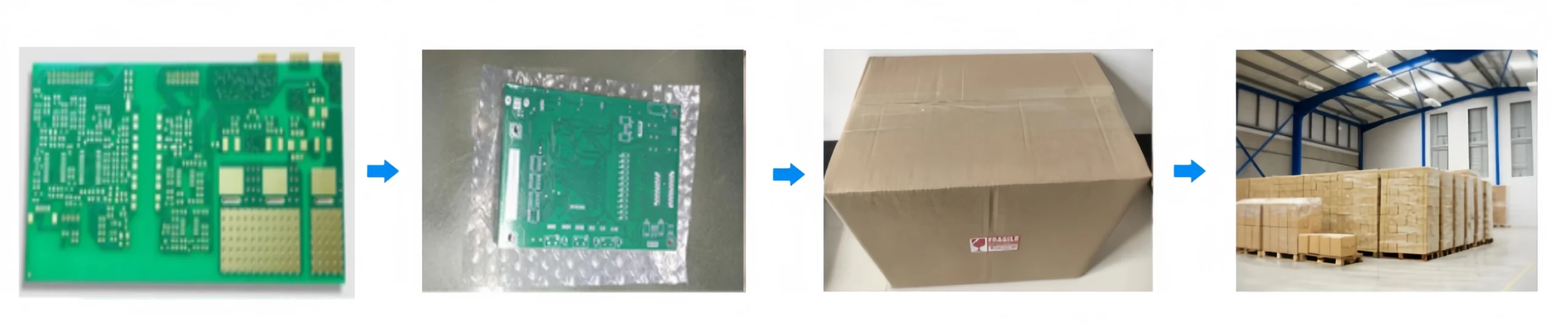
Aluminum Nitride Ceramic Housing Packaging
- Each aluminum nitride ceramic packaging shell is separated in rigid plastic trays or cavity blister packs to prevent edge chipping and surface contact.