Alumina Ceramic Hydrocyclone Liner for Slurry Classification (Custom ID/OD & Cone Angle)

ADCERAX provides standard liner sections for common cyclone sizes and produces custom alumina ceramic hydrocyclone liners from your drawing, measurement sheet, or sample, including stepped interfaces, tapered cones, and multi-section kits for easier changeout.

Catalog No. AT-YHL-XNC001
Material ≥ 92% Al2O3
Wall Thickness Range 1.5–25 mm
Inner Diameter Tolerance ±0.1 -3mm
Bulk Density 3.6–3.9 g/cm³
24H Standard Dispatch
Small Batch Support OEM
Factory Direct
Expert Engineering Support

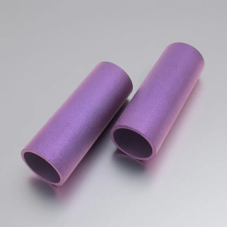
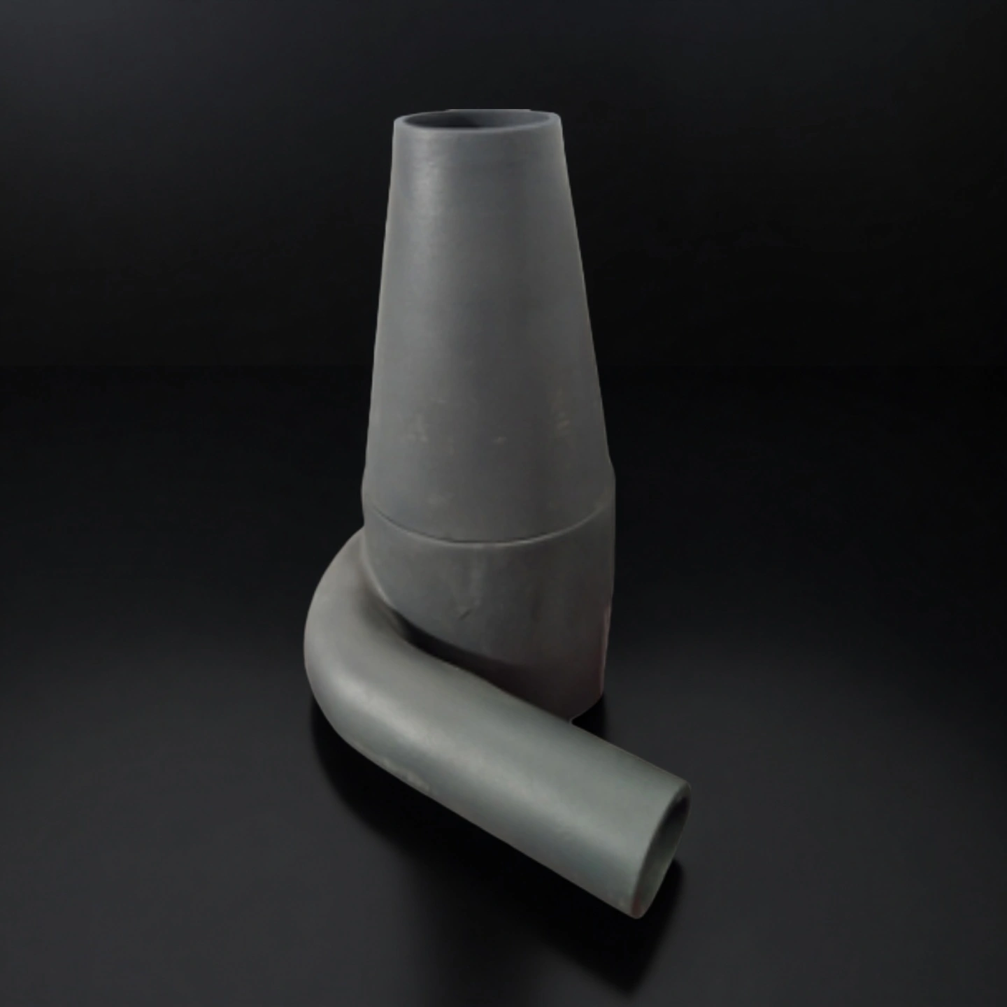
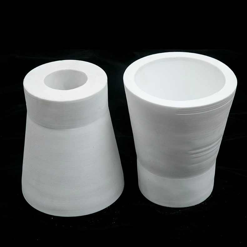
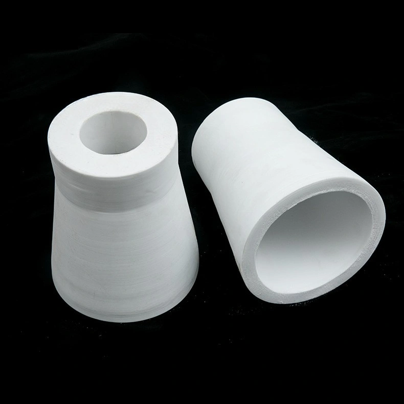
An Alumina Ceramic Hydrocyclone Liner is a replaceable wear insert installed inside a hydrocyclone (cyclone separator) to protect the cyclone body from abrasive slurry erosion and to keep the cyclone’s internal flow geometry stable during operation.

Alumina Ceramic Hydrocyclone Liner Advantages

  • Geometry retention focus: The alumina ceramic hydrocyclone liner is built to maintain a stable cone angle and internal ID profile over wear life, so the cyclone’s hydraulic geometry changes more slowly and separation performance stays closer to the initial setup.

  • Targeted wear-zone design: The liner can be designed with localized wall-thickness zoning in the highest-velocity impact band of the cone and near transition areas, which helps slow “grooving” and uneven thinning without adding unnecessary mass to low-wear regions.

  • Repeatable assembly fit: Controlled mating details such as seating length, shoulders, and step features support consistent positioning inside the cyclone body, reducing rocking, bypass flow at interfaces, and the localized edge erosion that often starts around misaligned joints.

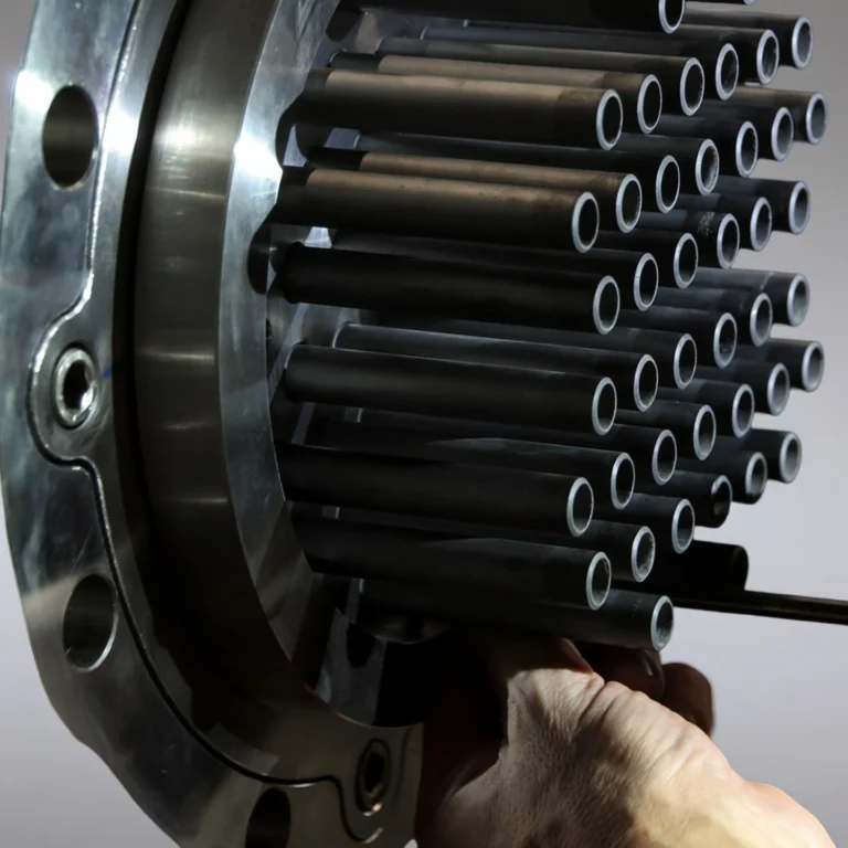
  • Kit-ready modularization: The alumina ceramic hydrocyclone liner can be structured as a modular set (barrel + cone + adapter sections) so the most-worn section can be replaced independently, while preserving the same internal flow-path geometry and avoiding a full liner teardown each time.

  • Erosion-path control: Internal transitions can be designed with smoother blends and minimized internal steps at section joints, helping reduce turbulence-driven hotspots that accelerate wear and cause early failure at seams, ends, or abrupt profile changes.


Alumina Ceramic Hydrocyclone Liner Properties

Property Unit 99.7% Al₂O₃ 99.5% Al₂O₃ 99% Al₂O₃ 96% Al₂O₃ 90%Al₂O₃
Color   Ivory White Ivory White Ivory White Ivory White White
Density g/cm³ 3.94 3.9 3.83 3.6-3.75 3.6-3.75
Water Absorption % 0 0 0 0 0
Hardness Mohs Hardness 9.1 9 9 8.8 8.7
Flexural Strength (20°C) Mpa 330 320 300 260 240
Compressive Strength (20°C) Mpa 2300 2300 2210 1910 1900
Maximum Operating Temperature °C 1730 1700 1680 1450 1100
Thermal Expansion Coefficient(25°C to 800°C) 10⁻⁶/°C 7.6 7.6 7.6 7.6 7.6
Thermal Conductivity (25°C) W/(m·K) 29 27 24 22 22
Dielectric Strength (5mm thickness) AC-kv/mm 22 21 19 15 15
Dielectric Loss at 25°C@1MHz --- < 0.0001 < 0.0001 0.0003 0.0004 0.0004
Dielectric Constant at 25°C@1MHz --- 9.8 9.7 9.5 9.2 9.2
Volume Resistivity (20°C) Ω·cm³ >10¹⁴ >10¹⁴ >10¹⁴ >10¹⁴ >10¹⁴
Volume Resistivity (300°C) Ω·cm³ 2*10¹² 2*10¹² 4*10¹¹ 2*10¹¹ 2*10¹¹

Alumina Ceramic Hydrocyclone Liner Specifications

Alumina Ceramic Hydrocyclone Liner
Item No. Outer Diameter (mm) Inner Diameter (mm) Thickness (mm) Length (mm) Tolerance(mm) Purity %
AT-YHL-XNC001 30 24 3 200 ±0.5mm 92-95
AT-YHL-XNC002 37 30 3.5 198 92-95
AT-YHL-XNC003 40 30 5 200 92-95
AT-YHL-XNC004 40 33 3.5 200 92-95
AT-YHL-XNC005 50 35 12.5 200 92-95
AT-YHL-XNC006 50 40 5 200 92-95
AT-YHL-XNC007 55 45 5 200 92-95
AT-YHL-XNC008 58 48 5 200 92-95
AT-YHL-XNC009 62 50 6 200 92-95
AT-YHL-XNC010 65 53 6 370 92-95
AT-YHL-XNC011 67 55 6 300 92-95
AT-YHL-XNC012 72 60 6 400 92-95
AT-YHL-XNC013 76 64 6 400 92-95
AT-YHL-XNC014 80 64 8 400 92-95
AT-YHL-XNC015 81 65 8 400 92-95
AT-YHL-XNC016 86 70 8 320 92-95
AT-YHL-XNC017 95 75 10 320 92-95
AT-YHL-XNC018 96 80 8 330 92-95
AT-YHL-XNC019 106 90 8 330 ±1mm 92-95
AT-YHL-XNC020 111 95 8 330 92-95
AT-YHL-XNC021 116 100 8 400 92-95
AT-YHL-XNC022 120 100 10 400 92-95
AT-YHL-XNC023 130 110 10 400 92-95
AT-YHL-XNC024 140 120 10 400 92-95
AT-YHL-XNC025 145 125 10 400 92-95
AT-YHL-XNC026 150 130 10 400 92-95
AT-YHL-XNC027 155 135 10 400 92-95
AT-YHL-XNC028 160 140 10 390 92-95
AT-YHL-XNC029 165 145 10 400 92-95
AT-YHL-XNC030 170 150 10 390 92-95
AT-YHL-XNC031 200 175 12.5 370 ±1.5mm 92-95
AT-YHL-XNC032 200 180 10 320 92-95
AT-YHL-XNC033 224 200 12 300 92-95
AT-YHL-XNC034 255 220 17.5 300 ±2.5mm 92-95
AT-YHL-XNC035 280 250 15 500 92-95
AT-YHL-XNC036 290 250 20 500 92-95
AT-YHL-XNC037 306 270 18 500 92-95
AT-YHL-XNC038 340 300 20 500 92-95
AT-YHL-XNC039 406 370 18 500 92-95
AT-YHL-XNC040 440 400 20 500 92-95
AT-YHL-XNC041 451 415 18 500 92-95
AT-YHL-XNC042 520 480 20 500 92-95


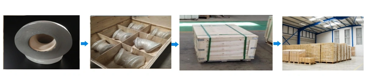
Alumina Hydrocyclone Liner Packaging

  • Individual protective packing: each liner section is wrapped and separated to prevent edge chipping during transport.
  • Foam-buffered carton: shock-absorbing internal supports for cone ends and seating edges.

Alumina Lining Tube Packaging

Alumina Ceramic Hydrocyclone Liner Applications

  • (Mining & Mineral Processing) Cyclone Clusters for Classification

    ✅Key Advantages

    1. Downtime risk framing: unplanned downtime in heavy industry is commonly cited at ~$187,500/hour, so reducing emergency liner failures protects production windows.

    2. Cut-size stability lever: maintaining cone ID and apex region geometry reduces separation drift caused by progressive wear in high-solids slurry.

    3. Wear-zone reinforcement: targeted thickness at the cone high-velocity band helps extend changeout intervals without oversizing the entire liner.

    ✅ Problem Solved

    A copper concentrator running a cyclone cluster saw increasing recirculating load and frequent apex-related interventions after liner wear progressed unevenly. The maintenance team reduced emergency changeouts by switching to a modular liner set with reinforced cone wear zones and consistent seating features. Replacement events were scheduled into planned stops instead of mid-shift failures. The plant used the same interface geometry across batches to simplify spare holding and reduce “fit surprises” during shutdown windows.

  • (Sand Washing & Aggregates) Fine Sand Recovery Hydrocyclones

    ✅Key Advantages

    1. Erosion intensity reality: silica-rich sand slurry creates rapid erosion at the cone and joint transitions, making geometry retention more valuable than “just thicker walls.”

    2. Modular changeout: multi-section liners can reduce replacement labor time by keeping heavy shell work unchanged while swapping only worn sections.

    3. Low absorption spec: ≤0.2% water absorption supports stable seating and reduces micro-spalling risk from repeated wet/dry cycles.

    ✅ Problem Solved

    A wet-processing line experienced frequent liner replacements during peak throughput, creating missed dispatch windows. By using a split liner design (barrel + cone sections) with controlled seating lengths, the team shortened maintenance interventions and reduced misalignment-related bypass flow. The liner set was standardized so operators could swap only the worn cone section instead of removing the full assembly. The result was fewer unscheduled stops and more consistent product gradation across production shifts.

  • (Oil & Gas/Produced Water) Desanding Hydrocyclones

    ✅Key Advantages

    1. Hardness for erosion zones: ~1200–1600 HV alumina hardness supports longer service in high-velocity sand impact regions.

    2. Interface accuracy: controlled steps and seating lands reduce bypass erosion and edge chipping at assembly joints.

    3. Smooth transitions: reduced turbulence at joints helps slow localized erosion that often triggers early liner failure.

    ✅ Problem Solved

    A produced-water desanding unit faced frequent erosion at the cone section and early failure at the liner interface edge. The liner design was adjusted with smoother internal transitions and a more stable seating land to reduce bypass flow and edge impact. Maintenance intervals became more predictable, allowing spares planning rather than reactive purchasing. The site reduced urgent freight events and improved uptime consistency in high-flow sand removal service.

Alumina Ceramic Hydrocyclone Liner Usage Instructions

  • Installation

    1. Verify cyclone shell seating surfaces are clean and free of burrs before inserting the alumina ceramic hydrocyclone liner.
    2. Confirm the liner type (single-piece insert vs multi-piece kit) and match each section to its position code (barrel / cone / adapter).
    3. Dry-fit the liner sections first to confirm seating length, shoulder contact, and interface alignment before final clamping.
    4. Check that stop faces fully contact the seat; partial contact can create rocking and accelerated edge wear.
    5. Use controlled insertion force; avoid hammering on ceramic edges or cone tips.
    6. Ensure joint transitions are flush; any internal step inside the flow path can become an erosion hotspot.
    7. Confirm apex/vortex interfaces match the intended clearance; misfit can cause bypass flow and rapid localized wear.

  • Operation

    1. Stabilize feed conditions when possible; large surges accelerate erosion near cone transitions and at section joints.
    2. Avoid running the cyclone dry; dry particle impact can chip edges and initiate cracks.
    3. Monitor pressure drop, overflow clarity, and underflow pattern; sudden changes can indicate liner wear, misalignment, or partial blockage.
    4. Avoid prolonged operation with excessive vibration; vibration often amplifies joint fretting and edge chipping.
    5. Keep solids concentration within the intended operating window; overly high solids can increase particle-to-wall impact intensity.
    6. Watch for “short-circuiting” symptoms (unexpected coarse in overflow); this may indicate vortex finder interface wear or internal step formation.
    7. If using multi-cyclone clusters, compare performance across units; one cyclone drifting early may point to a fit issue rather than normal wear.

  • Storage

    1. Store liners in original protective packaging with separators between ceramic parts.
    2. Keep away from moisture cycling and temperature shock (warehouse doors, outdoor exposure, direct sunlight on cartons).
    3. Do not place heavy items directly on cone tips or thin lips; support parts at thicker sections.
    4. Keep parts dry and dust-free; grit on seating surfaces can create point-loading during installation.
    5. For long storage, keep cartons on pallets and away from floor moisture; recheck packaging integrity before use.
    6. Maintain section labeling during storage so kits are not mixed across different cyclone positions or models.

  • Cleaning

    1. Rinse slurry residue with water after shutdown; avoid aggressive scraping on ceramic edges and joint faces.
    2. Use non-metallic tools (plastic/wood) for deposits at interfaces to prevent chipping at seating edges.
    3. Do not use impact methods to remove hardened scale; soak/soften first, then remove gently.
    4. Clean and inspect joint faces and seating lands; deposits here often cause misalignment on reinstallation.
    5. Fully dry before re-packaging to reduce moisture-related handling damage and contamination risk.
    6. If chemical cleaning is used, verify compatibility with your specific slurry residue and plant procedures; rinse thoroughly afterward.

  • Common Issues + Practical Fix

    1. Issue: Uneven wear band or rapid wear near a joint
    Likely cause: internal step at interface, misalignment, or bypass flow.
    Fix: re-check seating faces and joint flushness; replace the mating section pair if the interface is worn.

    2. Issue: Liner loosens or “rocks” after a short run
    Likely cause: contaminated seat, burrs, or incomplete shoulder contact.
    Fix: clean/true the seat, confirm stop-face contact, and tighten symmetrically with controlled torque.

    3. Issue: Edge chipping during installation/removal
    Likely cause: metal tool contact, prying at thin lips, or point impacts.
    Fix: use protected push points, non-metal tools, and support the part from thicker zones during handling.

FAQ — Alumina Ceramic Hydrocyclone Liner

  1. Q: How do I choose the correct alumina ceramic hydrocyclone liner when I don’t have drawings?
    A: You can match an alumina ceramic hydrocyclone liner by measuring ID/OD at fixed points, cone angle, section lengths, and all seating steps, then verifying a dry-fit before final installation.
  2. Q: Which dimensions affect separation performance the most for an alumina ceramic hydrocyclone liner?
    A: The internal ID profile, cone angle, vortex finder seating geometry, and apex/spigot transition features have the strongest influence on flow pattern and cut-size stability in an alumina ceramic hydrocyclone liner setup.
  3. Q: Where does an alumina ceramic hydrocyclone liner typically wear fastest, and why?
    A: Most wear concentrates in the cone high-velocity band, joint transitions, and the apex region because particle impact energy and turbulence are highest in those zones for an alumina ceramic hydrocyclone liner.
  4. Q: When should I replace an alumina ceramic hydrocyclone liner—by hours, tons, or wear limit?
    A: Replacement is best triggered by a measured ID/profile drift at defined checkpoints and interface conditions, because runtime alone does not capture changes in slurry abrasiveness for an alumina ceramic hydrocyclone liner.
  5. Q: How do I prevent bypass flow that accelerates wear around the alumina ceramic hydrocyclone liner interfaces?
    A: Confirm full seating contact, keep joints flush inside the flow path, maintain correct clearance at vortex finder and apex interfaces, and avoid mixing heavily worn mating parts with a new alumina ceramic hydrocyclone liner section.
  6. Q: What information should I provide to quote and manufacture an alumina ceramic hydrocyclone liner accurately?
    A: Provide the cyclone model (if known), service slurry details, a drawing or sample, and a dimension list covering ID/OD profile points, cone angle, seating steps, joint style, and vortex finder/apex interface requirements for the alumina ceramic hydrocyclone liner.

Customer Reviews about Alumina Ceramic Hydrocyclone Liner

  • ⭐️⭐️⭐️⭐️⭐️
    We compared two suppliers and chose the ADCERAX factory because the alumina ceramic hydrocyclone liner interfaces matched our shell seats with minimal rework, and the pricing held stable on repeat orders.
    -- Mark Reynolds — Procure-to-Pay Manager, North Ridge Mining Services
  • ⭐️⭐️⭐️⭐️⭐️
    As a supplier, ADCERAX delivered an alumina ceramic hydrocyclone liner kit with clear section labeling and consistent dimensions across batches, which reduced our internal QA time.
    -- Sofia Klein — Spare Parts Buyer, Rhein Process Equipment GmbH
  • ⭐️⭐️⭐️⭐️⭐️
    The modular alumina ceramic hydrocyclone liner let us swap the worn cone section without touching the full assembly, and we saw fewer emergency changeouts during peak throughput.
    -- Daniel Ortiz — Maintenance Superintendent, Sierra Sands Wet Processing
  • ⭐️⭐️⭐️⭐️⭐️
    We requested a custom alumina ceramic hydrocyclone liner profile to reduce erosion at the interface step, and the revised transition geometry improved run consistency in sand impact service.
    -- Hannah Lee — Process Engineer, Coastal Desanding Operations
customize size

 Alumina Ceramic Hydrocyclone Liner Customized

We customize alumina ceramic hydrocyclone liners to match your cyclone’s installed geometry, assembly interface, and wear zones, delivered as single-piece inserts or modular liner kits.

  • ID/OD & taper profile: straight + cone sections, bore profile matching, local ID control for wear-zone stability

  • Cone geometry: cone angle, cone length, barrel length, transition radii between sections

  • Fit & locating features: seating length, shoulders/steps, stop faces, anti-rotation flats/notches

  • Joint & interface details: joint type (butt/step/tongue-groove style), internal step control, edge protection chamfers

  • Vortex finder interface: seat depth, clearance zone, alignment land, interface ring design (if used)

  • Apex/spigot interface: seat land, throat transition, outlet alignment features, erosion-buffer geometry

  • Wear-zone thickness zoning: reinforced cone wear band, localized thickening at impact hotspots, balanced wall thickness for assembly

  • Surface finish options: as-fired internal surface, ground seating surfaces, localized finishing at critical interfaces


Related Products

ADCERAX - Your Trusted Advanced Ceramics Manufacturing Partner

Direct factory manufacturing with comprehensive ceramic materials expertise and global supply capabilities

Direct Factory Manufacturing

China-based ceramic materials production facility with state-of-the-art equipment

Engineering Team

Experienced professionals in advanced ceramics applications and custom design

Quality Control

Strict quality control standards for technical ceramics manufacturing and quality management

Global Supply Chain

Serving customers worldwide with technical ceramics and rapid response

24/7 Technical Support

Round-the-clock support for ceramic components inquiries and technical assistance

500+ Satisfied Customers

Trusted by global customers for advanced ceramic materials and precision components

Get in touch with us

Our team will be happy to respond to you in less than 24 hours.

Adcerax's factory

Quick Quotation

*Our team will answer your inquiries within 24 hours.

*Your information will be kept strictly confidential.

Ready to Solve Your Engineering Challenge?

Partner with ADCERAX for reliable, high-performance advanced ceramic solutions. Our engineers are ready to discuss your project.

E-mail

info@adcerax.com

Phone

+(86) 0731-74427743 | WhatsApp: +(86) 19311583352

Response Time

Within 24 hours

Quick Quote

The more details you provide, the faster we can quote.

*We respond within 24 hours. All inquiries are confidential.

Download Catalog

Get Your Custom Sulution

The more details you provide, the faster we can respond.

customize size

*We respond within 24 hours. All inquiries are confidential.

Download Catalog