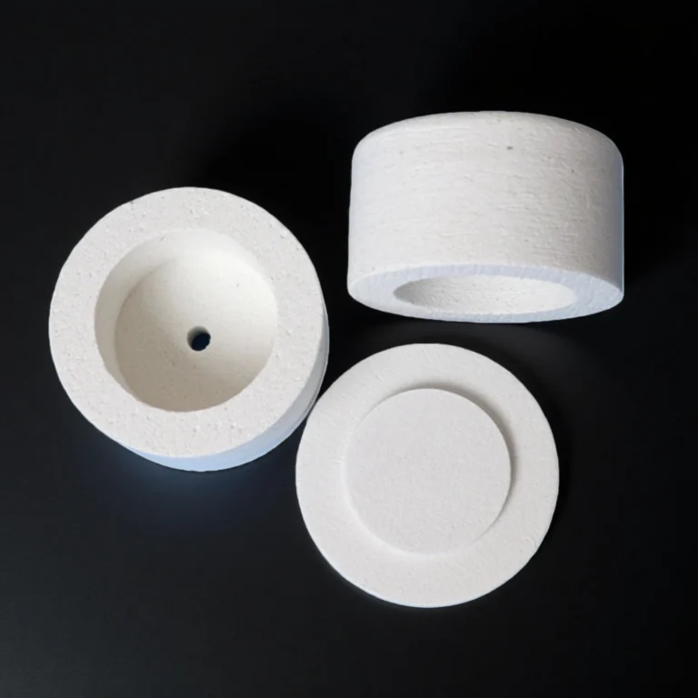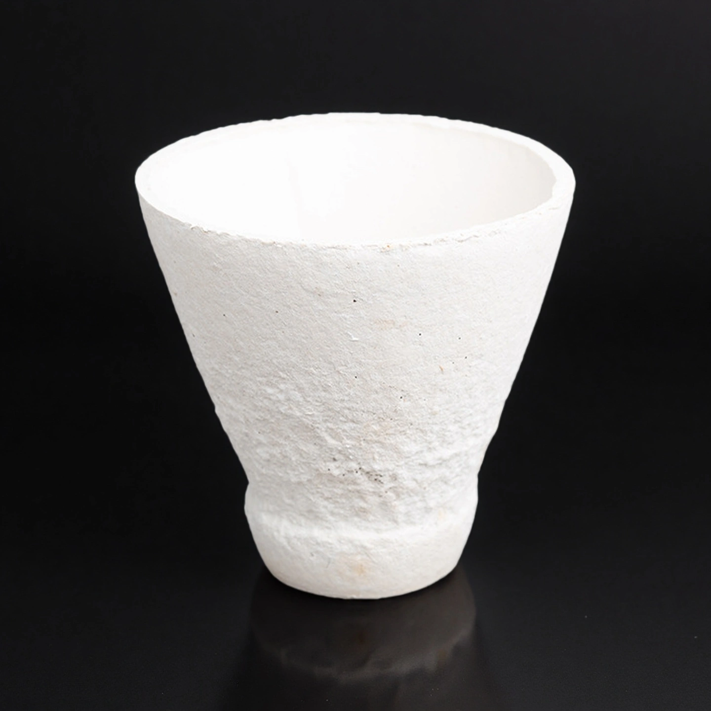
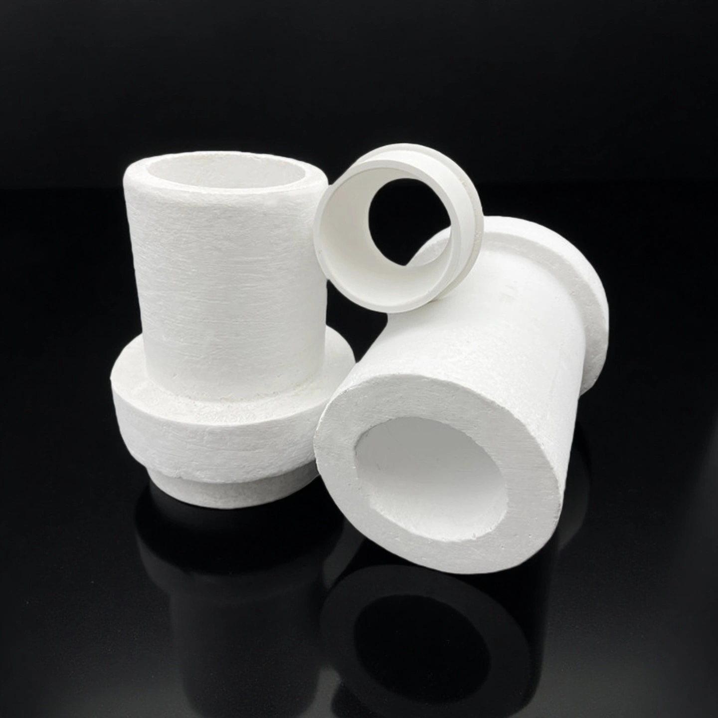
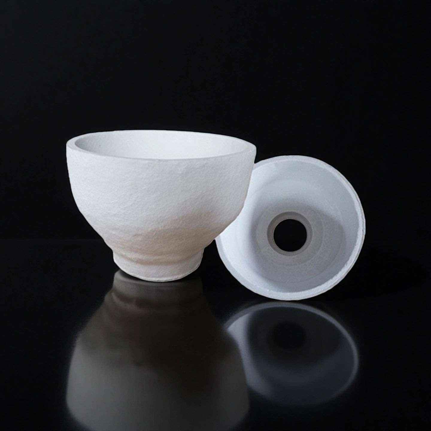
Aluminum silicate ceramic pouring cups are refractory gating components used at the top of the down sprue in investment casting to receive molten metal, calm the flow, and feed it into the ceramic shell with reduced turbulence and inclusions. Typical high alumina silicate formulations withstand up to around 1650 °C and are suitable for steel, stainless steel and high-temperature alloy castings.
Aluminum Silicate Pouring Cup Benefits
-
Stable geometry in the shell – The rigid aluminum silicate body bonds well to the ceramic shell, providing a stable impact zone for molten metal and lowering the chance of shell breakage at the sprue entrance.
-
Controlled flow and fewer inclusions – The smooth inner surface and optimized cup profile help reduce re-oxidation, air entrainment and slag roll-in, supporting lower inclusion-related scrap in precision castings.
-
Thermal shock resistance at casting temperatures – High alumina silicate compositions combine refractoriness up to 1650 °C with good thermal shock resistance, enabling repeated preheat–pour cycles without premature cup cracking.
-
Compatibility with investment mold materials – Aluminum silicate and mullite-based cups are designed to be chemically compatible with typical silica and alumina-based investment shell systems, minimizing reaction at the metal–mold interface.
-
Adaptable to multiple alloys – One pouring cup material can support ferrous, nickel-aluminium, bronze-based and selected superalloy systems, which simplifies consumable management in multi-alloy foundries.
Aluminum Silicate Pouring Cup Properties
| Aluminum Silicate Ceramic | ||
| Parameter | Typical Value | Notes / Industrial Relevance |
| Material Composition | Al₂O₃–SiO₂ | Silicate-based refractory matrix |
| Working Temperature | 1000–1400°C | Depends on density & grade |
| Bulk Density | 200–400 kg/m³ | Lower density = better insulation |
| Thermal Conductivity | 0.08–0.22 W/m·K | Measured at 600–1000°C |
| Linear Shrinkage | ≤ 2% at 1000–1300°C | Ensures dimensional stability |
| Cold Crushing Strength | 0.6–1.2 MPa | Resistance to mechanical load |
| Thermal Shock Resistance | High | Suitable for rapid heating cycles |
| Water Absorption | Low | Supports clean installation |
| Available Thickness | 10–75 mm | Custom thickness on request |
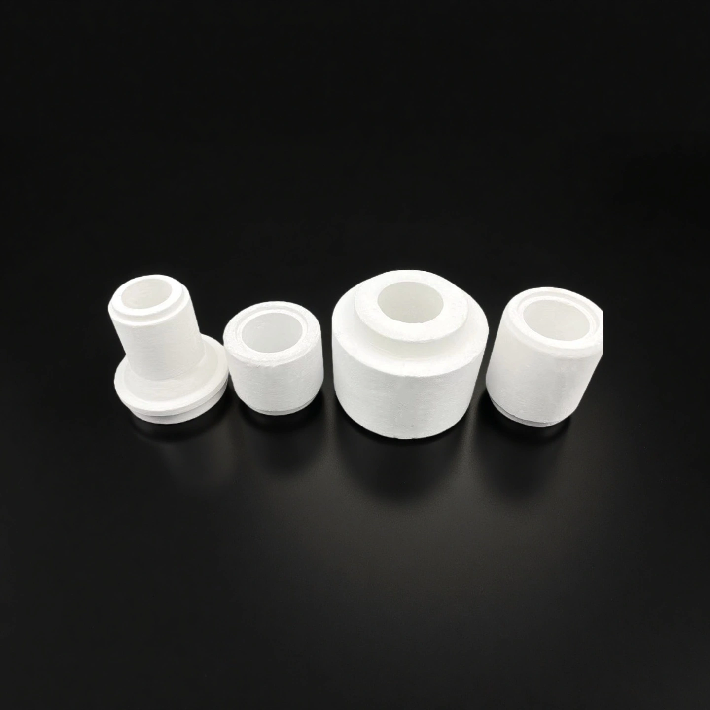
| Available Forms | Boards, blocks, custom-machined shapes | Supports OEM engineering designs |
Aluminium Silicate Pouring Cup Specification

| Square Aluminium Silicate Pouring Cup | ||||
| Item | Top Dia (mm) | Bottom Dia (mm) | Height(mm) | Thickness (mm) |
| AT-GSL-JK1004 | 50 | 30 | 110 | 8 |
| AT-GSL-JK1005 | 105 | 55 | 90 | 8 |
| AT-GSL-JK1006 | 105 | 50 | 150 | 8 |
| AT-GSL-JK1007 | 110 | 40 | 100 | 8 |
| AT-GSL-JK1008 | 110 | 60 | 120 | 8 |
| AT-GSL-JK1009 | 110 | 80 | 60 | 8 |
| AT-GSL-JK1010 | 140 | 40 | 125 | 8 |
| AT-GSL-JK1011 | 140 | 45 | 180 | 8 |
| AT-GSL-JK1012 | 155 | 50 | 155 | 8 |
| AT-GSL-JK1013 | 170 | 70 | 175 | 8 |
| AT-GSL-JK1014 | 180 | 38 | 160 | 8 |
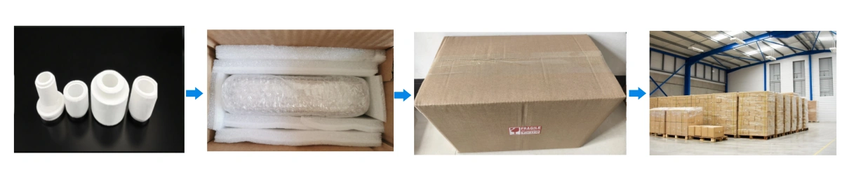
Aluminium Silicate Ceramic Pouring Cup Packaging
- Each aluminum silicate ceramic pouring cup is separated in carton cells or layered cardboard trays to avoid impact and edge chipping during transport.