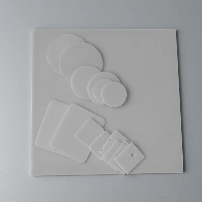
Bare aluminum nitride substrates are high-purity AlN ceramic plates supplied without any metallization, circuits or coatings on the surface. They are the “raw” ceramic base that downstream processes use to build advanced electronic and optoelectronic packages. They provides heat spreading and electrical insulation for high-power, high-reliability electronic assemblies.
Advantages of Bare Aluminium Nitride Substrates
-
High heat spreading capacity – bare AlN substrate with thermal conductivity typically ≥170 W/m·K helps lower junction-to-case thermal resistance compared with alumina substrates around 20–30 W/m·K.
-
CTE matched to semiconductor chips – coefficient of thermal expansion close to silicon and SiC reduces thermo-mechanical stress during power cycling and solder reflow.
-
High dielectric strength in thin profiles – bare aluminum nitride ceramic substrate maintains dielectric breakdown strength typically above 15 kV/mm even at reduced thickness, enabling compact isolation distances.
-
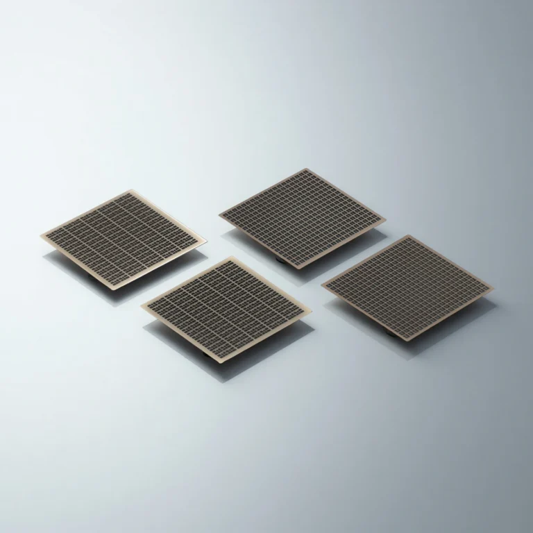
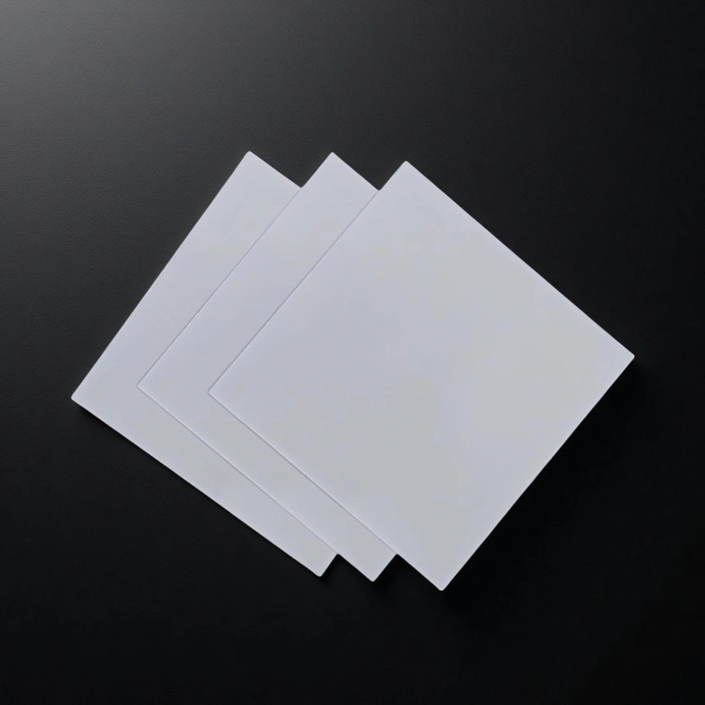
Stable surface for metallization and patterning – low-porosity AlN substrate body supports thick film, thin film, DBC/AMB and direct plated copper processing when needed in downstream steps.
-
Suitable for repeated thermal cycling – the combination of high thermal conductivity and compatible CTE improves resistance to cracking and delamination in modules with thousands of on/off cycles.
Bare Aluminum Nitride Ceramic Substrate Properties
| Property Content | Unit | Unit | ALN-170 | ALN-200 | ALN-230 |
| Basic Properties | Color | gray | light yellow | light yellow | |
| Density | g/cm³ | 3.2-3.3 | 3.2-3.3 | 3.2-3.3 | |
| Surface Roughness | μm | 0.2-0.75 | 0.2-0.75 | 0.2-0.8 | |
| Camber | length ‰ | ≤3‰ | ≤3‰ | ≤3‰ | |
| Hardness | HV | 1100 | 1100 | 1100 | |
| Thermal Properties | Max Operating Temperature | °C | 1100 | 1100 | 1100 |
| Thermal Conductivity | W/m·K | 170-190 | 190-220 | 220-230 | |
| Coefficient of Thermal Expansion | 10⁻⁶/K(20-400°c) | 4-5 | 4-5 | 4-5 | |
| Coefficient of Thermal Expansion | 10⁻⁶/K(400-800°c) | 5-6 | 5-6 | 5-6 | |
| Mechanical Properties | Flexural Strength | MPa | 300-400 | 350-450 | 400-500 |
| Tensile Strength | MPa | 200-300 | 250-350 | 280-380 | |
| Compressive Strength | MPa | 2000-3000 | 2200-3200 | 2500-3500 | |
| Electrical properties | Dielectric Constant | at 1MHz | 8-9 | 8-9 | 8-9 |
| Dielectric strength | KV/mm | ≥15 | ≥15 | ≥15 | |
| Volume resistivity | 20℃ Ω.cm | ≥1014 | ≥1014 | ≥1014 |
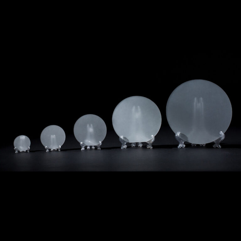
Specifications of Aluminium Nitride Substrates
Dimensional Tolerance information
| Item | AN-170 | AN-200 | AN-230 |
|---|---|---|---|
| Boundary Dimension | 5.5" x 7.5" | 5.0" x 7.0" | 5.0" x 7.0" |
| ±1% NLT: ±0.1mm | ±1% NLT: ±0.1mm | ±1% NLT: ±0.1mm | |
| Thickness | 0.25~1.5 | 0.25~1.5 | 0.25~0.635 |
| ±10% NLT: ±0.04mm | ±10% NLT: ±0.04mm | ±10% NLT: ±0.04mm | |
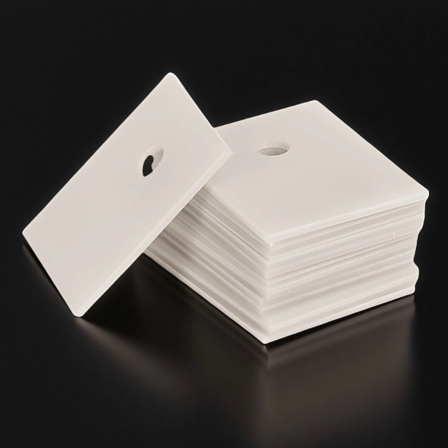
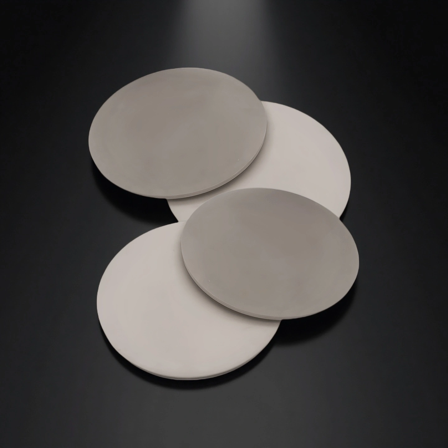
| Hole | Φ0.2~ | Φ0.2~ | Φ0.2~ |
| ±0.6% NLT: ±0.05mm | ±0.6% NLT: ±0.05mm | ±0.6% NLT: ±0.05mm | |
| Rate of Curving | 0.003/mm | 0.003/mm | 0.003/mm |
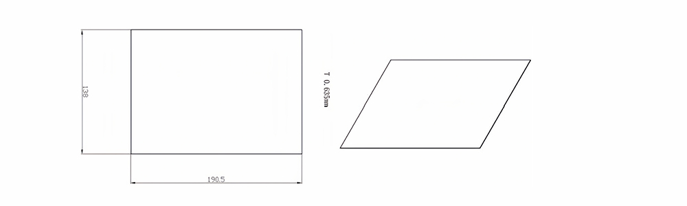
Type 1-AT-AIN-ZT-003
| Item No. | L x W x Thickness (mm) | Tolerance of Length and Width (mm) | Tolerance of Thickness (mm) | Thickness Range (mm) | Surface Roughness (μm) | Thermal Conductivity (25°C, W/m·k) | Bending Strength (MPa) |
|---|---|---|---|---|---|---|---|
| AT-AIN-ZT-003 | 138 x 190.5 x 0.635 | ±0.1 | ±0.05 | 0.38 - 3.0 | Ra 0.2 - 0.6 | >170 | >420 |
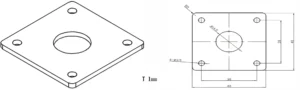
Type 2-AT-AIN-ZT-004
| Item No. | L x W x Thickness (mm) | Tolerance of Length and Width (mm) | Tolerance of Thickness (mm) | Thickness Range (mm) | Surface Roughness (μm) | Thermal Conductivity (25°C, W/m·k) | Bending Strength (MPa) |
|---|---|---|---|---|---|---|---|
| AT-AIN-ZT-004 | 114.3 x 114.3 x 0.5 | ±0.1 | ±0.05 | 0.25 - 3.0 | Ra 0.2 - 0.6 | >170 | >420 |
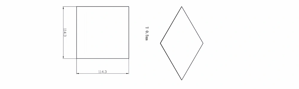
Type 3-AT-AIN-ZT-005
| Item No. | L x W x Thickness (mm) | Tolerance of Length and Width (mm) | Tolerance of Thickness (mm) | Thickness Range (mm) | Surface Roughness (μm) | Thermal Conductivity (25°C, W/m·k) | Bending Strength (MPa) |
|---|---|---|---|---|---|---|---|
| AT-AIN-ZT-005 | 120 x 120 x 1.0 | ±0.1 | ±0.05 | 0.25 - 3.0 | Ra 0.2 - 0.6 | >170 | >420 |
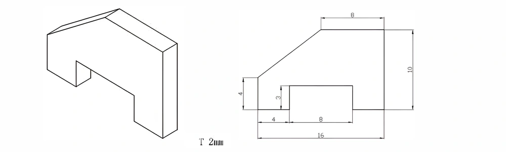
Type 4-AT-AIN-ZT-006
| Item No. | L x W x Thickness (mm) | Tolerance of Length and Width (mm) | Tolerance of Thickness (mm) | Thickness Range (mm) | Surface Roughness (μm) | Thermal Conductivity (25°C, W/m·k) | Bending Strength (MPa) |
|---|---|---|---|---|---|---|---|
| AT-AIN-ZT-006 | 16 x 10 x 2.0 | ±0.1 | ±0.05 | 0.25 - 3.0 | Ra 0.2 - 0.6 | >170 | >420 |
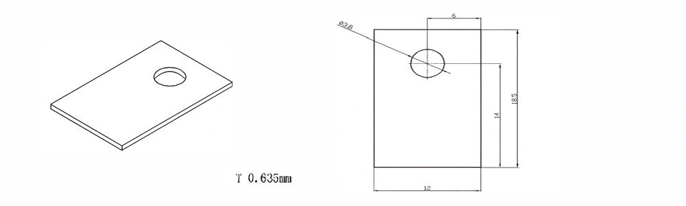
Type 5-AT-AIN-ZT-007
| Item No. | L x W x Thickness (mm) | Tolerance of Length and Width (mm) | Tolerance of Thickness (mm) | Thickness Range (mm) | Surface Roughness (μm) | Thermal Conductivity (25°C, W/m·k) | Bending Strength (MPa) |
|---|---|---|---|---|---|---|---|
| AT-AIN-ZT-007 | 18.5 x 12 x 0.635 | ±0.1 | ±0.05 | 0.25 - 3.0 | Ra 0.2 - 0.6 | >170 | >420 |
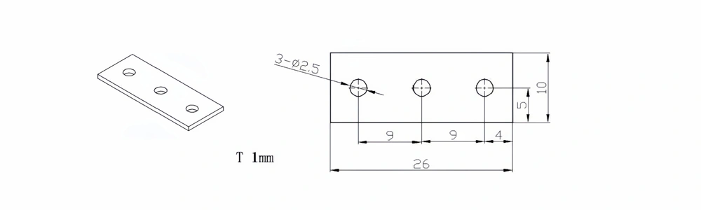
Type 6-AT-AIN-ZT-008
| Item No. | L x W x Thickness (mm) | Tolerance of Length and Width (mm) | Tolerance of Thickness (mm) | Thickness Range (mm) | Surface Roughness (μm) | Thermal Conductivity (25°C, W/m·k) | Bending Strength (MPa) |
|---|---|---|---|---|---|---|---|
| AT-AIN-ZT-008 | 26 x 10 x 1.0 | ±0.1 | ±0.05 | 0.25 - 3.0 | Ra 0.2 - 0.6 | >170 | >420 |
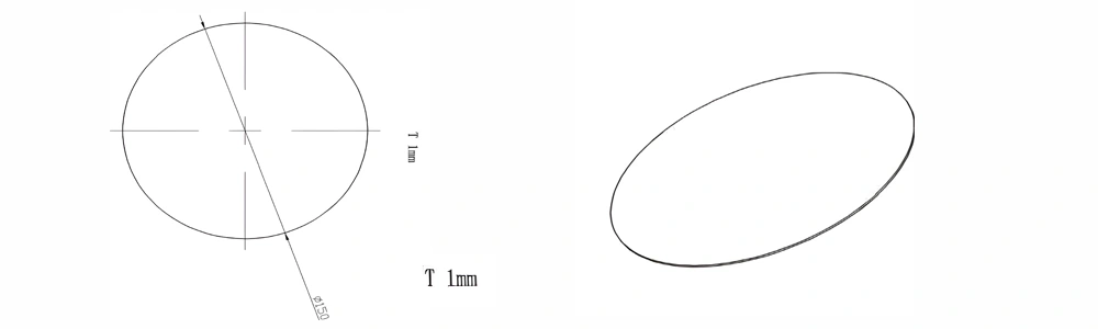
Type 7-AT-AIN-ZT-009
| Item No. | Diameter x Thickness (mm) | Tolerance of Diameter (mm) | Tolerance of Thickness (mm) | Thickness Range (mm) | Surface Roughness (μm) | Thermal Conductivity (25°C, W/m·k) | Bending Strength (MPa) |
|---|---|---|---|---|---|---|---|
| AT-AIN-ZT-009 | φ150 x 1.0 | ±0.1 | ±0.05 | 0.5 - 3.0 | Ra 0.2 - 0.6 | >170 | >420 |
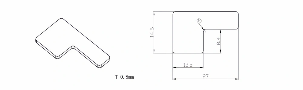
Type 8-AT-AIN-ZT-010
| Item No. | L x W x Thickness (mm) | Tolerance of Length and Width (mm) | Tolerance of Thickness (mm) | Thickness Range (mm) | Surface Roughness (μm) | Thermal Conductivity (25°C, W/m·k) | Bending Strength (MPa) |
|---|---|---|---|---|---|---|---|
| AT-AIN-ZT-010 | 27 x 14.6 x 0.8 | ±0.1 | ±0.05 | 0.25 - 3.0 | Ra 0.2 - 0.6 | >170 | >420 |
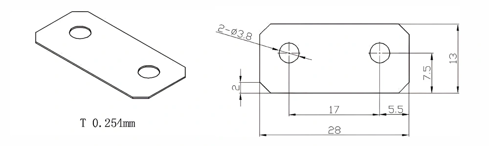
Type 9-AT-AIN-ZT-011
| Item No. | L x W x Thickness (mm) | Tolerance of Length and Width (mm) | Tolerance of Thickness (mm) | Thickness Range (mm) | Surface Roughness (μm) | Thermal Conductivity (25°C, W/m·k) | Bending Strength (MPa) |
|---|---|---|---|---|---|---|---|
| AT-AIN-ZT-011 | 28 x 13 x 0.254 | ±0.1 | ±0.05 | 0.25 - 3.0 | Ra 0.2 - 0.6 | >170 | >420 |
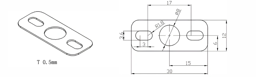
Type 10-AT-AIN-ZT-012
| Item No. | L x W x Thickness (mm) | Tolerance of Length and Width (mm) | Tolerance of Thickness (mm) | Thickness Range (mm) | Surface Roughness (μm) | Thermal Conductivity (25°C, W/m·k) | Bending Strength (MPa) |
|---|---|---|---|---|---|---|---|
| AT-AIN-ZT-012 | 30 x 12 x 0.5 | ±0.1 | ±0.05 | 0.25 - 3.0 | Ra 0.2 - 0.6 | >170 | >420 |
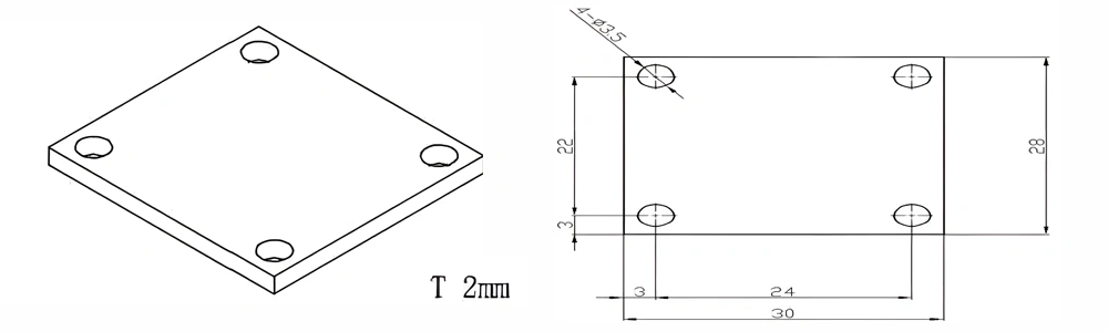
Type 11-AT-AIN-ZT-013
| Item No. | L x W x Thickness (mm) | Tolerance of Length and Width (mm) | Tolerance of Thickness (mm) | Thickness Range (mm) | Surface Roughness (μm) | Thermal Conductivity (25°C, W/m·k) | Bending Strength (MPa) |
|---|---|---|---|---|---|---|---|
| AT-AIN-ZT-013 | 30 x 28 x 2.0 | ±0.1 | ±0.05 | 0.25 - 3.0 | Ra 0.2 - 0.6 | >170 | >420 |
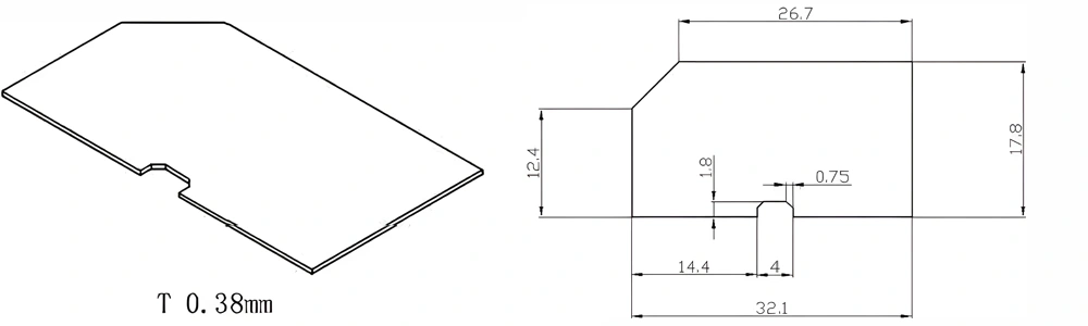
Type 12-AT-AIN-ZT-014
| Item No. | L x W x Thickness (mm) | Tolerance of Length and Width (mm) | Tolerance of Thickness (mm) | Thickness Range (mm) | Surface Roughness (μm) | Thermal Conductivity (25°C, W/m·k) | Bending Strength (MPa) |
|---|---|---|---|---|---|---|---|
| AT-AIN-ZT-014 | 32.1 x 17.8 x 0.38 | ±0.1 | ±0.05 | 0.25 - 3.0 | Ra 0.2 - 0.6 | >170 | >420 |
Type 13-AT-AIN-ZT-015

| Item No. | Diameter x Thickness (mm) | Tolerance of Diameter (mm) | Tolerance of Thickness (mm) | Thickness Range (mm) | Surface Roughness (μm) | Thermal Conductivity (25°C, W/m·k) | Bending Strength (MPa) |
|---|---|---|---|---|---|---|---|
| AT-AIN-ZT-015 | φ200 x 1.0 | ±0.1 | ±0.05 | 0.75 - 3.0 | Ra 0.2 - 0.6 | >170 | >420 |
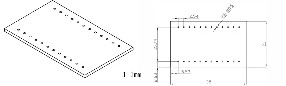
Type 14-AT-AIN-ZT-016
| Item No. | L x W x Thickness (mm) | Tolerance of Length and Width (mm) | Tolerance of Thickness (mm) | Thickness Range (mm) | Surface Roughness (μm) | Thermal Conductivity (25°C, W/m·k) | Bending Strength (MPa) |
|---|---|---|---|---|---|---|---|
| AT-AIN-ZT-016 | 35 x 21 x 1.0 | ±0.1 | ±0.05 | 0.25 - 3.0 | Ra 0.2 - 0.6 | >170 | >420 |
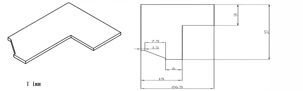
Type 15-AT-AIN-ZT-017
| Item No. | L x W x Thickness (mm) | Tolerance of Length and Width (mm) | Tolerance of Thickness (mm) | Thickness Range (mm) | Surface Roughness (μm) | Thermal Conductivity (25°C, W/m·k) | Bending Strength (MPa) |
|---|---|---|---|---|---|---|---|
| AT-AIN-ZT-017 | 37 x 26.5 x 1.0 | ±0.1 | ±0.05 | 0.25 - 3.0 | Ra 0.2 - 0.6 | >170 | >420 |
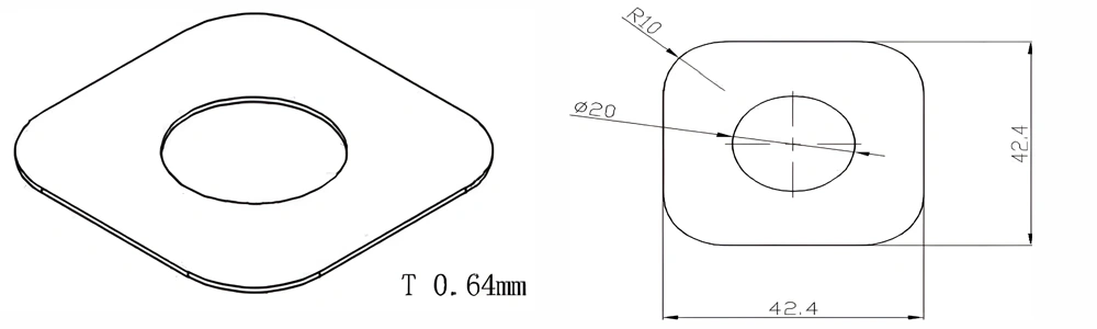
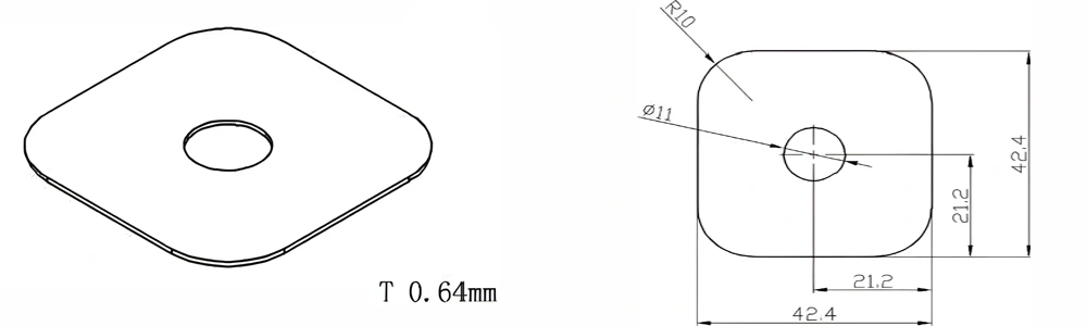
Type 16-AT-AIN-ZT-018
| Item No. | L x W x Thickness (mm) | Tolerance of Length and Width (mm) | Tolerance of Thickness (mm) | Thickness Range (mm) | Surface Roughness (μm) | Thermal Conductivity (25°C, W/m·k) | Bending Strength (MPa) |
|---|---|---|---|---|---|---|---|
| AT-AIN-ZT-018 | 42.4 x 42.4 x 0.64 | ±0.1 | ±0.05 | 0.25 - 3.0 | Ra 0.2 - 0.6 | >170 | >420 |
Type 17-AT-AIN-ZT-019
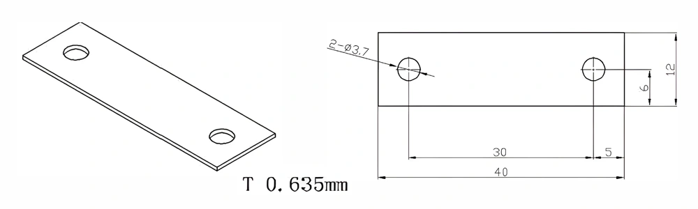
| Item No. | L x W x Thickness (mm) | Tolerance of Length and Width (mm) | Tolerance of Thickness (mm) | Thickness Range (mm) | Surface Roughness (μm) | Thermal Conductivity (25°C, W/m·k) | Bending Strength (MPa) |
|---|---|---|---|---|---|---|---|
| AT-AIN-ZT-019 | 40 x 12 x 0.635 | ±0.1 | ±0.05 | 0.25 - 3.0 | Ra 0.2 - 0.6 | >170 | >420 |
Type 18-AT-AIN-ZT-020
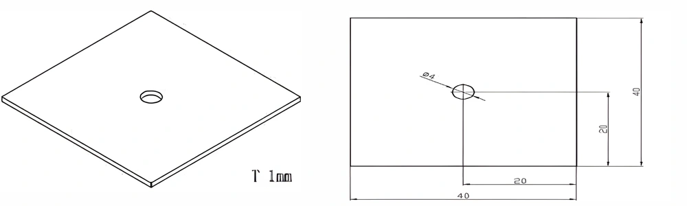
| Item No. | L x W x Thickness (mm) | Tolerance of Length and Width (mm) | Tolerance of Thickness (mm) | Thickness Range (mm) | Surface Roughness (μm) | Thermal Conductivity (25°C, W/m·k) | Bending Strength (MPa) |
|---|---|---|---|---|---|---|---|
| AT-AIN-ZT-020 | 40 x 40 x 1.0 | ±0.1 | ±0.05 | 0.25 - 3.0 | Ra 0.2 - 0.6 | >170 | >420 |
Type 19-AT-AIN-ZT-021
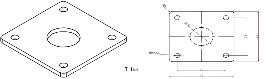
| Item No. | L x W x Thickness (mm) | Tolerance of Length and Width (mm) | Tolerance of Thickness (mm) | Thickness Range (mm) | Surface Roughness (μm) | Thermal Conductivity (25°C, W/m·k) | Bending Strength (MPa) |
|---|---|---|---|---|---|---|---|
| AT-AIN-ZT-021 | 40 x 40 x 1.0 | ±0.1 | ±0.05 | 0.25 - 3.0 | Ra 0.2 - 0.6 | >170 | >420 |
Type 20-AT-AIN-ZT-022
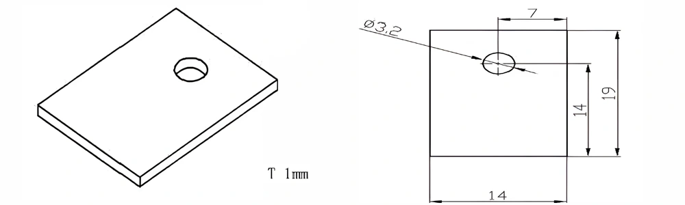
| Item No. | L x W x Thickness (mm) | Tolerance of Length and Width (mm) | Tolerance of Thickness (mm) | Thickness Range (mm) | Surface Roughness (μm) | Thermal Conductivity (25°C, W/m·k) | Bending Strength (MPa) |
|---|---|---|---|---|---|---|---|
| AT-AIN-ZT-022 | 19 x 14 x 1.0 | ±0.1 | ±0.05 | 0.25 - 3.0 | Ra 0.2 - 0.6 | >170 | >420 |
Type 21-AT-AIN-ZT-023
| Item No. | L x W x Thickness (mm) | Tolerance of Length and Width (mm) | Tolerance of Thickness (mm) | Thickness Range (mm) | Surface Roughness (μm) | Thermal Conductivity (25°C, W/m·k) | Bending Strength (MPa) |
|---|---|---|---|---|---|---|---|
| AT-AIN-ZT-023 | 42.4*42.4*0.64mm | ±0.1 | ±0.05 | 0.25 - 3.0 | Ra 0.2 - 0.6 | >170 | >420 |
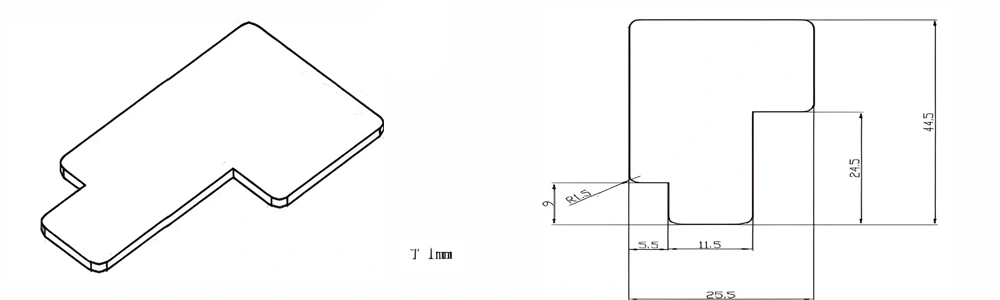
Type 22-AT-AIN-ZT-024
| Item No. | L x W x Thickness (mm) | Tolerance of Length and Width (mm) | Tolerance of Thickness (mm) | Thickness Range (mm) | Surface Roughness (μm) | Thermal Conductivity (25°C, W/m·k) | Bending Strength (MPa) |
|---|---|---|---|---|---|---|---|
| AT-AIN-ZT-024 | 44.5*25.5*1.0mm | ±0.1 | ±0.05 | 0.25 - 3.0 | Ra 0.2 - 0.6 | >170 | >420 |
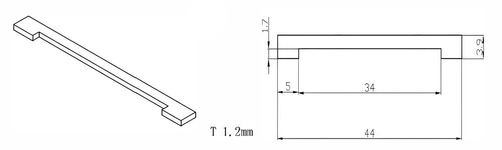
Type 23-AT-AIN-ZT-025
| Item No. | L x W x Thickness (mm) | Tolerance of Length and Width (mm) | Tolerance of Thickness (mm) | Thickness Range (mm) | Surface Roughness (μm) | Thermal Conductivity (25°C, W/m·k) | Bending Strength (MPa) |
|---|---|---|---|---|---|---|---|
| AT-AIN-ZT-025 | 44*3.9*1.2mm | ±0.1 | ±0.05 | 0.25 - 3.0 | Ra 0.2 - 0.6 | >170 | >420 |
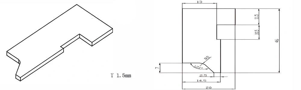
Type 24-AT-AIN-ZT-026
| Item No. | L x W x Thickness (mm) | Tolerance of Length and Width (mm) | Tolerance of Thickness (mm) | Thickness Range (mm) | Surface Roughness (μm) | Thermal Conductivity (25°C, W/m·k) | Bending Strength (MPa) |
|---|---|---|---|---|---|---|---|
| AT-AIN-ZT-026 | 46*20*1.5mm | ±0.1 | ±0.05 | 0.25 - 3.0 | Ra 0.2 - 0.6 | >170 | >420 |
Type 25-AT-AIN-ZT-027

| Item No. | L x W x Thickness (mm) | Tolerance of Length and Width (mm) | Tolerance of Thickness (mm) | Thickness Range (mm) | Surface Roughness (μm) | Thermal Conductivity (25°C, W/m·k) | Bending Strength (MPa) |
|---|---|---|---|---|---|---|---|
| AT-AIN-ZT-027 | φ300*1.0mm | ±0.1 | ±0.05 | 1.0mm-3.0mm | Ra 0.2 - 0.6 | >170 | >420 |
Type 26-AT-AIN-ZT-028
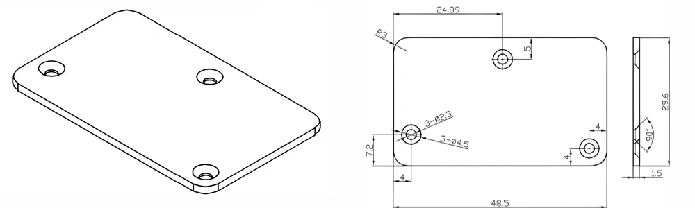
| Item No. | L x W x Thickness (mm) | Tolerance of Length and Width (mm) | Tolerance of Thickness (mm) | Thickness Range (mm) | Surface Roughness (μm) | Thermal Conductivity (25°C, W/m·k) | Bending Strength (MPa) |
|---|---|---|---|---|---|---|---|
| AT-AIN-ZT-028 | 48.5*29.6*1.5mm | ±0.1 | ±0.05 | 0.25mm-3.0mm | Ra 0.2 - 0.6 | >170 | >420 |
Type 27-AT-AIN-ZT-029
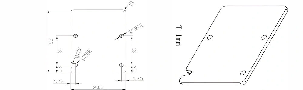
| Item No. | L x W x Thickness (mm) | Tolerance of Length and Width (mm) | Tolerance of Thickness (mm) | Thickness Range (mm) | Surface Roughness (μm) | Thermal Conductivity (25°C, W/m·k) | Bending Strength (MPa) |
|---|---|---|---|---|---|---|---|
| AT-AIN-ZT-029 | 28*20.5*1.0mm | ±0.1 | ±0.05 | 0.25mm-3.0mm | Ra0.2-0.6 | >170 | >420 |
Type 28-AT-AIN-ZT-030
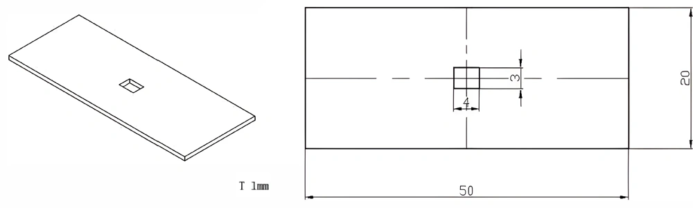
| Item No. | L x W x Thickness (mm) | Tolerance of Length and Width (mm) | Tolerance of Thickness (mm) | Thickness Range (mm) | Surface Roughness (μm) | Thermal Conductivity (25°C, W/m·k) | Bending Strength (MPa) |
|---|---|---|---|---|---|---|---|
| AT-AIN-ZT-030 | 50*20*1.0mm | ±0.1 | ±0.05 | 0.25mm-3.0mm | Ra0.2-0.6 | >170 | >420 |
Type 29-AT-AIN-ZT-031
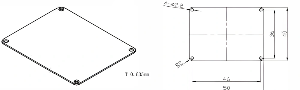
| Item No. | L x W x Thickness (mm) | Tolerance of Length and Width (mm) | Tolerance of Thickness (mm) | Thickness Range (mm) | Surface Roughness (μm) | Thermal Conductivity (25°C, W/m·k) | Bending Strength (MPa) |
|---|---|---|---|---|---|---|---|
| AT-AIN-ZT-031 | 50*40*0.635mm | ±0.1 | ±0.05 | 0.25mm-3.0mm | Ra0.2-0.6 | >170 | >420 |
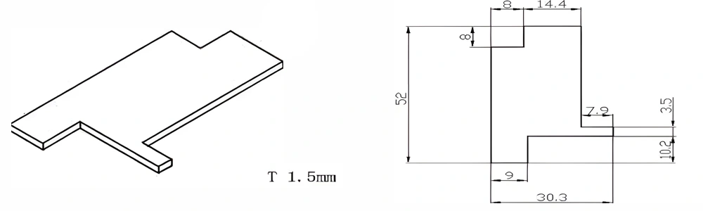
Type 30-AT-AIN-ZT-032
| Item No. | L x W x Thickness (mm) | Tolerance of Length and Width (mm) | Tolerance of Thickness (mm) | Thickness Range (mm) | Surface Roughness (μm) | Thermal Conductivity (25°C, W/m·k) | Bending Strength (MPa) |
|---|---|---|---|---|---|---|---|
| AT-AIN-ZT-032 | 52*30.3*1.5mm | ±0.1 | ±0.05 | 0.25mm-3.0mm | Ra0.2-0.6 | >170 | >420 |
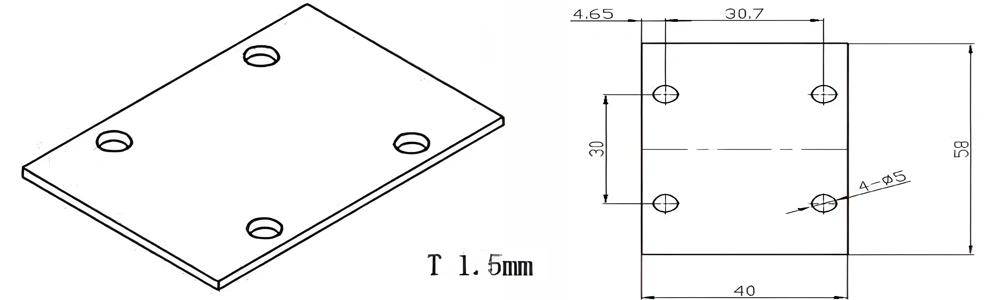
Type 31-AT-AIN-ZT-033
| Item No. | L x W x Thickness (mm) | Tolerance of Length and Width (mm) | Tolerance of Thickness (mm) | Thickness Range (mm) | Surface Roughness (μm) | Thermal Conductivity (25°C, W/m·k) | Bending Strength (MPa) |
|---|---|---|---|---|---|---|---|
| AT-AIN-ZT-033 | 58*40*1.5mm | ±0.1 | ±0.05 | 0.25mm-3.0mm | Ra0.2-0.6 | >170 | >420 |
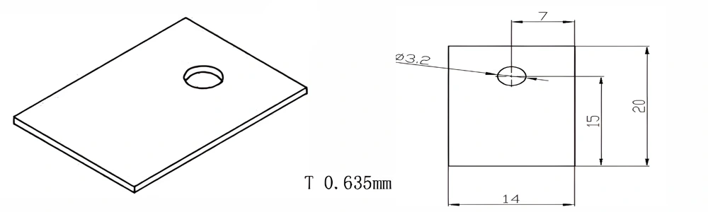
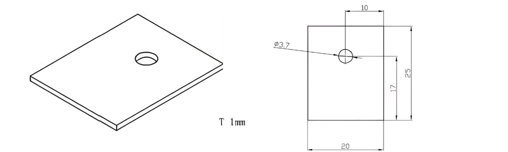
Type 32-AT-AIN-ZT-034
| Item No. | L x W x Thickness (mm) | Tolerance of Length and Width (mm) | Tolerance of Thickness (mm) | Thickness Range (mm) | Surface Roughness (μm) | Thermal Conductivity (25°C, W/m·k) | Bending Strength (MPa) |
|---|---|---|---|---|---|---|---|
| AT-AIN-ZT-034 | 20*14*0.635mm | ±0.1 | ±0.05 | 0.25mm-3.0mm | Ra0.2-0.6 | >170 | >420 |
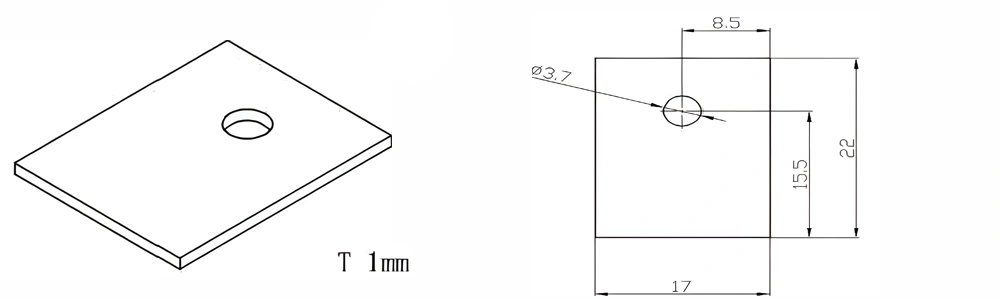
Type 33-AT-AIN-ZT-035
| Item No. | L x W x Thickness (mm) | Tolerance of Length and Width (mm) | Tolerance of Thickness (mm) | Thickness Range (mm) | Surface Roughness (μm) | Thermal Conductivity (25°C, W/m·k) | Bending Strength (MPa) |
|---|---|---|---|---|---|---|---|
| AT-AIN-ZT-035 | 22*17*1.0mm | ±0.1 | ±0.05 | 0.25mm-3.0mm | Ra0.2-0.6 | >170 | >420 |
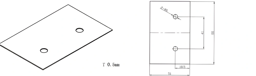
Type 34-AT-AIN-ZT-036
| Item No. | L x W x Thickness (mm) | Tolerance of Length and Width (mm) | Tolerance of Thickness (mm) | Thickness Range (mm) | Surface Roughness (μm) | Thermal Conductivity (25°C, W/m·k) | Bending Strength (MPa) |
|---|---|---|---|---|---|---|---|
| AT-AIN-ZT-036 | 80*51*0.5mm | ±0.1 | ±0.05 | 0.25mm-3.0mm | Ra0.2-0.6 | >170 | >420 |
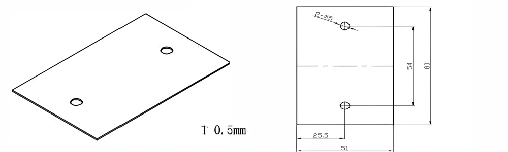
Type 35-AT-AIN-ZT-037
| Item No. | L x W x Thickness (mm) | Tolerance of Length and Width (mm) | Tolerance of Thickness (mm) | Thickness Range (mm) | Surface Roughness (μm) | Thermal Conductivity (25°C, W/m·k) | Bending Strength (MPa) |
|---|---|---|---|---|---|---|---|
| AT-AIN-ZT-037 | 70.2*51*1.5mm | ±0.1 | ±0.05 | 0.25mm-3.0mm | Ra0.2-0.6 | >170 | >420 |
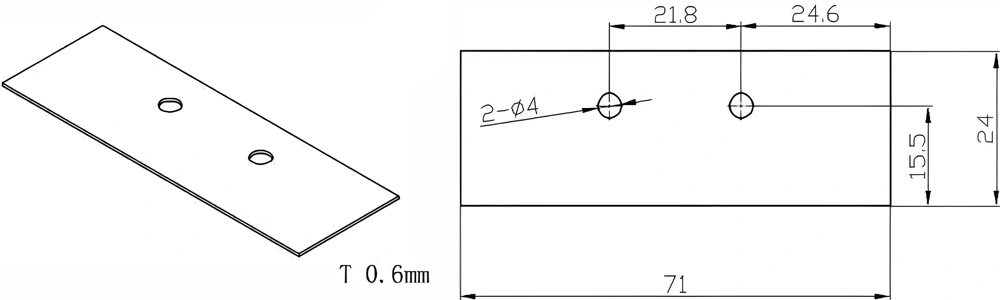
Type 36-AT-AIN-ZT-038
| Item No. | L x W x Thickness (mm) | Tolerance of Length and Width (mm) | Tolerance of Thickness (mm) | Thickness Range (mm) | Surface Roughness (μm) | Thermal Conductivity (25°C, W/m·k) | Bending Strength (MPa) |
|---|---|---|---|---|---|---|---|
| AT-AIN-ZT-038 | 71*24*0.6mm | ±0.1 | ±0.05 | 0.25mm-3.0mm | Ra0.2-0.6 | >170 | >420 |
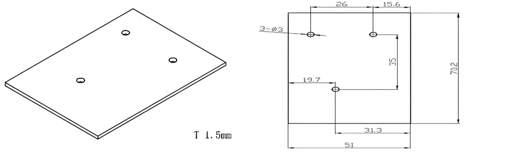
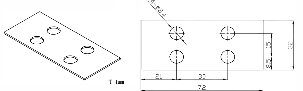
Type 37-AT-AIN-ZT-039
| Item No. | L x W x Thickness (mm) | Tolerance of Length and Width (mm) | Tolerance of Thickness (mm) | Thickness Range (mm) | Surface Roughness (μm) | Thermal Conductivity (25°C, W/m·k) | Bending Strength (MPa) |
|---|---|---|---|---|---|---|---|
| AT-AIN-ZT-039 | 72*32*1.0mm | ±0.1 | ±0.05 | 0.25mm-3.0mm | Ra0.2-0.6 | >170 | >420 |
Type 38-AT-AIN-ZT-040
| Item No. | L x W x Thickness (mm) | Tolerance of Length and Width (mm) | Tolerance of Thickness (mm) | Thickness Range (mm) | Surface Roughness (μm) | Thermal Conductivity (25°C, W/m·k) | Bending Strength (MPa) |
|---|---|---|---|---|---|---|---|
| AT-AIN-ZT-040 | 72*42*1.0mm | ±0.1 | ±0.05 | 0.25mm-3.0mm | Ra0.2-0.6 | >170 | >420 |
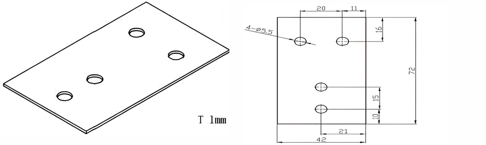
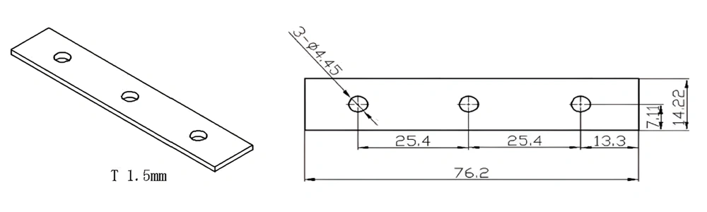
Type 39-AT-AIN-ZT-041
| Item No. | L x W x Thickness (mm) | Tolerance of Length and Width (mm) | Tolerance of Thickness (mm) | Thickness Range (mm) | Surface Roughness (μm) | Thermal Conductivity (25°C, W/m·k) | Bending Strength (MPa) |
|---|---|---|---|---|---|---|---|
| AT-AIN-ZT-041 | 76.2*14.22*1.5mm | ±0.1 | ±0.05 | 0.25mm-3.0mm | Ra0.2-0.6 | >170 | >420 |
Type 40-AT-AIN-ZT-042
| Item No. | L x W x Thickness (mm) | Tolerance of Length and Width (mm) | Tolerance of Thickness (mm) | Thickness Range (mm) | Surface Roughness (μm) | Thermal Conductivity (25°C, W/m·k) | Bending Strength (MPa) |
|---|---|---|---|---|---|---|---|
| AT-AIN-ZT-042 | 80*51*0.5mm | ±0.1 | ±0.05 | 0.25mm-3.0mm | Ra0.2-0.6 | >170 | >420 |
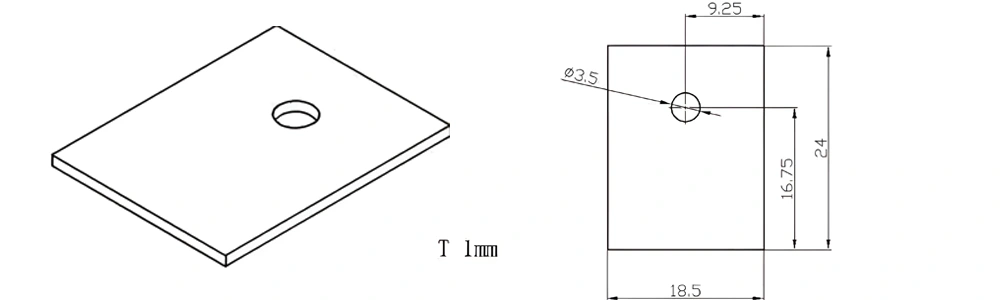
Type 41-AT-AIN-ZT-043
| Item No. | L x W x Thickness (mm) | Tolerance of Length and Width (mm) | Tolerance of Thickness (mm) | Thickness Range (mm) | Surface Roughness (μm) | Thermal Conductivity (25°C, W/m·k) | Bending Strength (MPa) |
|---|---|---|---|---|---|---|---|
| AT-AIN-ZT-043 | 24*18.5*1.0mm | ±0.1 | ±0.05 | 0.25mm-3.0mm | Ra0.2-0.6 | >170 | >420 |
Type 42-AT-AIN-ZT-044
| Item No. | L x W x Thickness (mm) | Tolerance of Length and Width (mm) | Tolerance of Thickness (mm) | Thickness Range (mm) | Surface Roughness (μm) | Thermal Conductivity (25°C, W/m·k) | Bending Strength (MPa) |
|---|---|---|---|---|---|---|---|
| AT-AIN-ZT-044 | 25*20*1.0mm | ±0.1 | ±0.05 | 0.25mm-3.0mm | Ra0.2-0.6 | >170 | >420 |
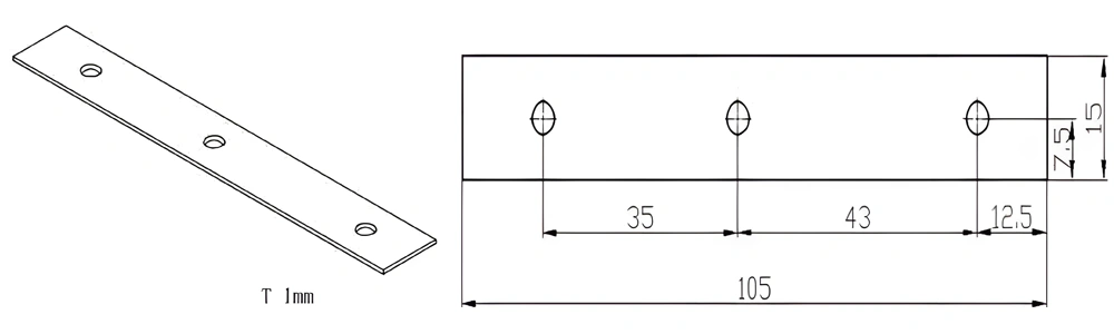
Type 43-AT-AIN-ZT-045
| Item No. | L x W x Thickness (mm) | Tolerance of Length and Width (mm) | Tolerance of Thickness (mm) | Thickness Range (mm) | Surface Roughness (μm) | Thermal Conductivity (25°C, W/m·k) | Bending Strength (MPa) |
|---|---|---|---|---|---|---|---|
| AT-AIN-ZT-045 | 105*15*1.0mm | ±0.1 | ±0.05 | 0.25mm-3.0mm | Ra0.2-0.6 | >170 | >420 |
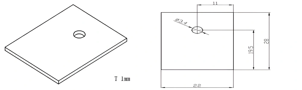
Type 44-AT-AIN-ZT-046
| Item No. | L x W x Thickness (mm) | Tolerance of Length and Width (mm) | Tolerance of Thickness (mm) | Thickness Range (mm) | Surface Roughness (μm) | Thermal Conductivity (25°C, W/m·k) | Bending Strength (MPa) |
|---|---|---|---|---|---|---|---|
| AT-AIN-ZT-046 | 28*22*1.0mm | ±0.1 | ±0.05 | 0.25mm-3.0mm | Ra0.2-0.6 | >170 | >420 |
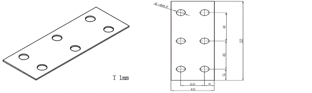
Type 45-AT-AIN-ZT-047
| Item No. | L x W x Thickness (mm) | Tolerance of Length and Width (mm) | Tolerance of Thickness (mm) | Thickness Range (mm) | Surface Roughness (μm) | Thermal Conductivity (25°C, W/m·k) | Bending Strength (MPa) |
|---|---|---|---|---|---|---|---|
| AT-AIN-ZT-047 | 112*40*1.0mm | ±0.1 | ±0.05 | 0.25mm-3.0mm | Ra0.2-0.6 | >170 | >420 |
Type 46-AT-AIN-ZT-048
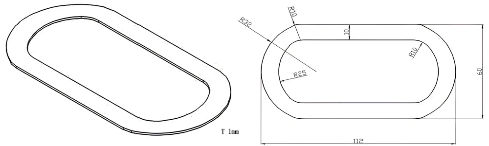
| Item No. | L x W x Thickness (mm) | Tolerance of Length and Width (mm) | Tolerance of Thickness (mm) | Thickness Range (mm) | Surface Roughness (μm) | Thermal Conductivity (25°C, W/m·k) | Bending Strength (MPa) |
|---|---|---|---|---|---|---|---|
| AT-AIN-ZT-048 | 112*60*1.0mm | ±0.1 | ±0.05 | 0.25mm-3.0mm | Ra0.2-0.6 | >170 | >420 |
Type 47-AT-AIN-ZT-049
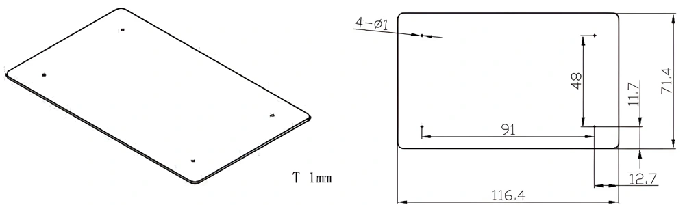
| Item No. | L x W x Thickness (mm) | Tolerance of Length and Width (mm) | Tolerance of Thickness (mm) | Thickness Range (mm) | Surface Roughness (μm) | Thermal Conductivity (25°C, W/m·k) | Bending Strength (MPa) |
|---|---|---|---|---|---|---|---|
| AT-AIN-ZT-049 | 116.4*71.4*1.0mm | ±0.1 | ±0.05 | 0.25mm-3.0mm | Ra0.2-0.6 | >170 | >420 |
Type 48-AT-AIN-ZT-050
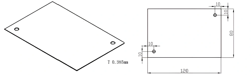
| Item No. | L x W x Thickness (mm) | Tolerance of Length and Width (mm) | Tolerance of Thickness (mm) | Thickness Range (mm) | Surface Roughness (μm) | Thermal Conductivity (25°C, W/m·k) | Bending Strength (MPa) |
|---|---|---|---|---|---|---|---|
| AT-AIN-ZT-050 | 120*80*0.385mm | ±0.1 | ±0.05 | 0.25mm-3.0mm | Ra0.2-0.6 | >170 | >420 |
Type 49-AT-AIN-ZT-051
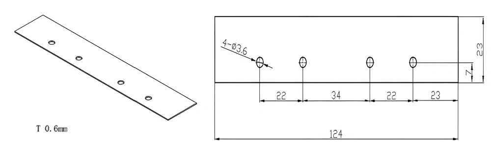
| Item No. | L x W x Thickness (mm) | Tolerance of Length and Width (mm) | Tolerance of Thickness (mm) | Thickness Range (mm) | Surface Roughness (μm) | Thermal Conductivity (25°C, W/m·k) | Bending Strength (MPa) |
|---|---|---|---|---|---|---|---|
| AT-AIN-ZT-051 | 124*23*0.6mm | ±0.1 | ±0.05 | 0.381mm-3.0mm | Ra0.2-0.6 | >170 | >420 |
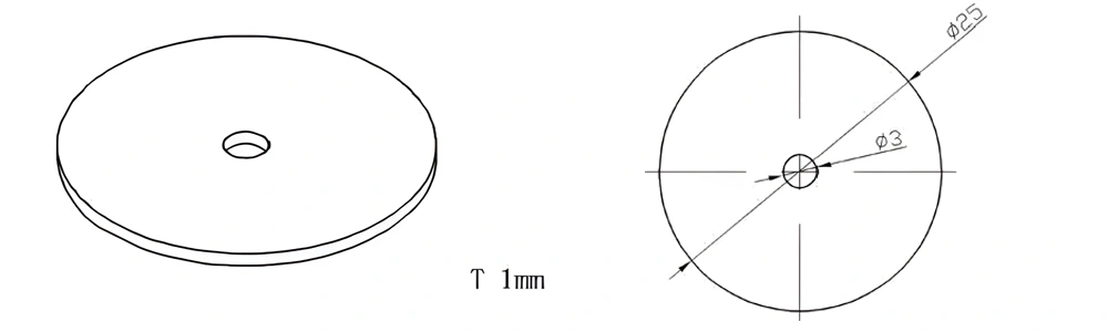
Type 50-AT-AIN-ZT-052
| Item No. | L x W x Thickness (mm) | Tolerance of Length and Width (mm) | Tolerance of Thickness (mm) | Thickness Range (mm) | Surface Roughness (μm) | Thermal Conductivity (25°C, W/m·k) | Bending Strength (MPa) |
|---|---|---|---|---|---|---|---|
| AT-AIN-ZT-052 | φ25*1.0mm | ±0.1 | ±0.05 | 0.25mm-3.0mm | Ra0.2-0.6 | >170 | >420 |
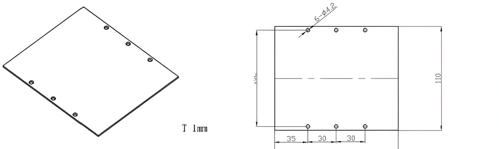
Type 51-AT-AIN-ZT-053
| Item No. | L x W x Thickness (mm) | Tolerance of Length and Width (mm) | Tolerance of Thickness (mm) | Thickness Range (mm) | Surface Roughness (μm) | Thermal Conductivity (25°C, W/m·k) | Bending Strength (MPa) |
|---|---|---|---|---|---|---|---|
| AT-AIN-ZT-053 | 130*110*1.0mm | ±0.1 | ±0.05 | 0.25mm-3.0mm | Ra0.2-0.6 | >170 | >420 |
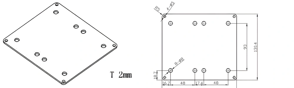
Type 52-AT-AIN-ZT-054
| Item No. | L x W x Thickness (mm) | Tolerance of Length and Width (mm) | Tolerance of Thickness (mm) | Thickness Range (mm) | Surface Roughness (μm) | Thermal Conductivity (25°C, W/m·k) | Bending Strength (MPa) |
|---|---|---|---|---|---|---|---|
| AT-AIN-ZT-054 | 146.8*130.4*2.0mm | ±0.1 | ±0.05 | 0.38mm-3.0mm | Ra0.2-0.6 | >170 | >420 |
Type 53-AT-AIN-ZT-055

| Item No. | L x W x Thickness (mm) | Tolerance of Length and Width (mm) | Tolerance of Thickness (mm) | Thickness Range (mm) | Surface Roughness (μm) | Thermal Conductivity (25°C, W/m·k) | Bending Strength (MPa) |
|---|---|---|---|---|---|---|---|
| AT-AIN-ZT-055 | 150*50*2.0mm | ±0.1 | ±0.05 | 0.5mm-3.0mm | Ra0.2-0.6 | >170 | >420 |
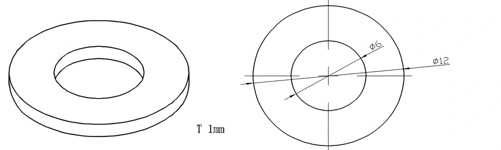
Type 54-AT-AIN-ZT-056
| Item No. | L x W x Thickness (mm) | Tolerance of Length and Width (mm) | Tolerance of Thickness (mm) | Thickness Range (mm) | Surface Roughness (μm) | Thermal Conductivity (25°C, W/m·k) | Bending Strength (MPa) |
|---|---|---|---|---|---|---|---|
| AT-AIN-ZT-056 | φ12*1.0mm | ±0.1 | ±0.05 | 0.25mm-3.0mm | Ra0.2-0.6 | >170 | >420 |
Type 55-AT-AIN-ZT-057
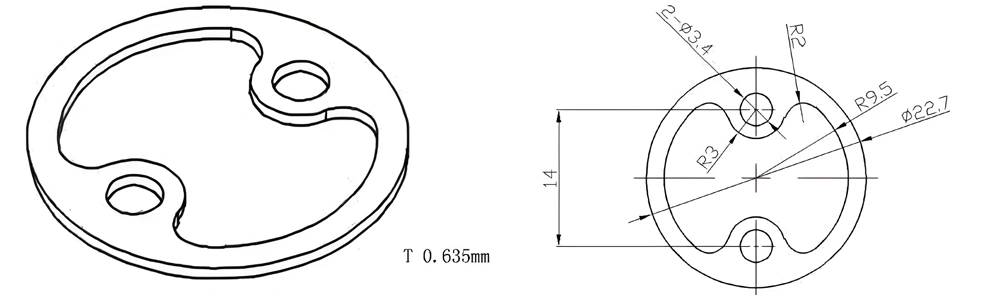
| Item No. | L x W x Thickness (mm) | Tolerance of Length and Width (mm) | Tolerance of Thickness (mm) | Thickness Range (mm) | Surface Roughness (μm) | Thermal Conductivity (25°C, W/m·k) | Bending Strength (MPa) |
|---|---|---|---|---|---|---|---|
| AT-AIN-ZT-057 | φ22.7*0.635mm | ±0.1 | ±0.05 | 0.25mm-3.0mm | Ra0.2-0.6 | >170 | >420 |
Type 56-AT-AIN-ZT-058
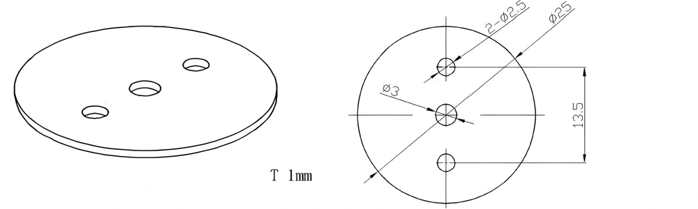
| Item No. | L x W x Thickness (mm) | Tolerance of Length and Width (mm) | Tolerance of Thickness (mm) | Thickness Range (mm) | Surface Roughness (μm) | Thermal Conductivity (25°C, W/m·k) | Bending Strength (MPa) |
|---|---|---|---|---|---|---|---|
| AT-AIN-ZT-058 | φ25*1.0mm | ±0.1 | ±0.05 | 0.25mm-3.0mm | Ra0.2-0.6 | >170 | >420 |
Type 57-AT-AIN-ZT-059
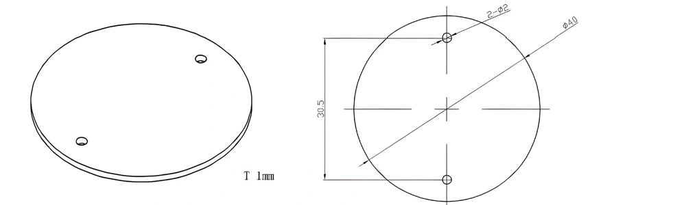
| Item No. | L x W x Thickness (mm) | Tolerance of Length and Width (mm) | Tolerance of Thickness (mm) | Thickness Range (mm) | Surface Roughness (μm) | Thermal Conductivity (25°C, W/m·k) | Bending Strength (MPa) |
|---|---|---|---|---|---|---|---|
| AT-AIN-ZT-059 | φ40*1.0mm | ±0.1 | ±0.05 | 0.25mm-3.0mm | Ra0.2-0.6 | >170 | >420 |
Type 58-AT-AIN-ZT-060
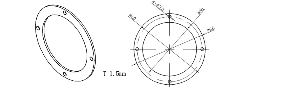
| Item No. | L x W x Thickness (mm) | Tolerance of Length and Width (mm) | Tolerance of Thickness (mm) | Thickness Range (mm) | Surface Roughness (μm) | Thermal Conductivity (25°C, W/m·k) | Bending Strength (MPa) |
|---|---|---|---|---|---|---|---|
| AT-AIN-ZT-060 | φ66*1.5mm | ±0.1 | ±0.05 | 0.25mm-3.0mm | Ra0.2-0.6 | >170 | >420 |
Type 59-AT-AIN-ZT-061
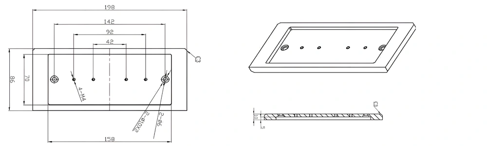
| Item No. | L x W x Thickness (mm) | Tolerance of Length and Width (mm) | Tolerance of Thickness (mm) | Thickness Range (mm) | Surface Roughness (μm) | Thermal Conductivity (25°C, W/m·k) | Bending Strength (MPa) |
|---|---|---|---|---|---|---|---|
| AT-AIN-ZT-061 | 198*158*10mm | ±0.1 | ±0.05 | 5mm-20mm | Ra0.2-0.6 | >170 | >420 |
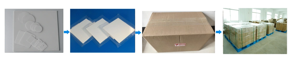
Bare AlN Substrate Packaging
- Clean tray packing – each bare aluminum nitride substrate is separated in rigid plastic trays or cavity blister packs so that edges and functional surfaces do not contact each other during transport.