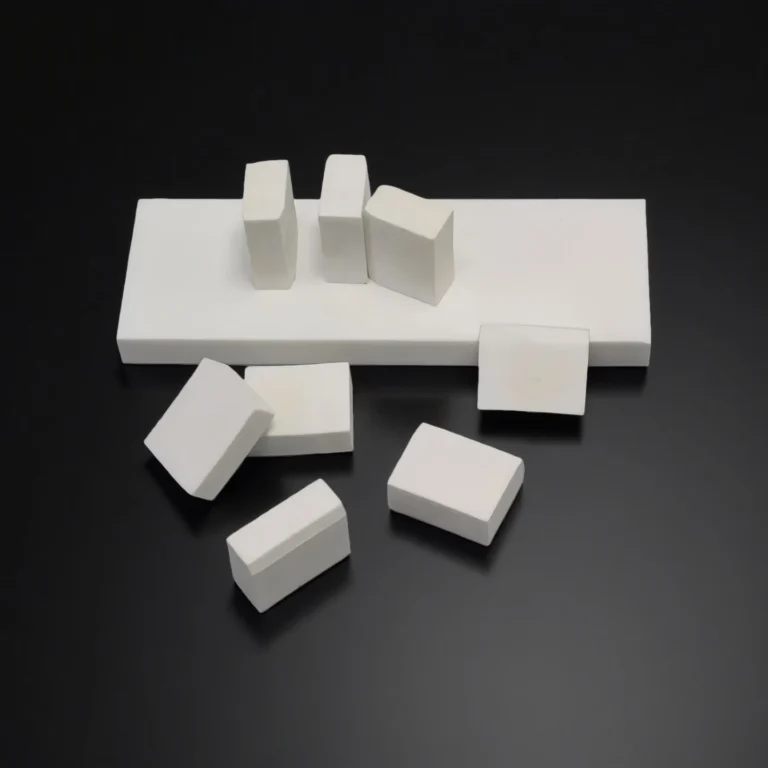
Boron carbide plate is a solid, flat or curved component made from boron carbide (chemical formula B₄C) — one of the hardest known advanced ceramics, ranking just below diamond and cubic boron nitride in hardness. It combines exceptional mechanical strength, low density, and chemical stability, making it ideal for neutron absorption, radiation shielding, and industrial wear protection applications.
Boron Carbide Plates Advantages
- High hardness with low density: ~2.48 g/cm³ and ≥ 30 GPa hardness help achieve strong impact/erosion resistance at lower mass.
- Neutron absorption capability: B-10 isotope enables efficient neutron capture for shielding and absorber modules.
- Wear & chemical resistance: Suitable for abrasive slurries and corrosive streams; extends lining service life.
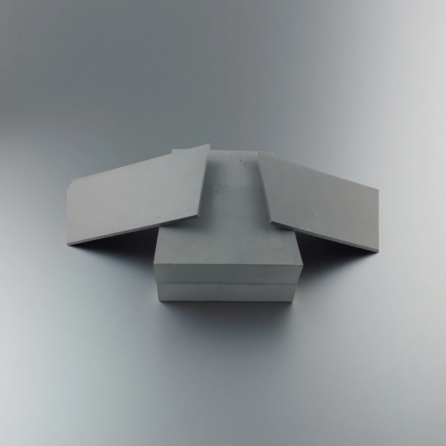
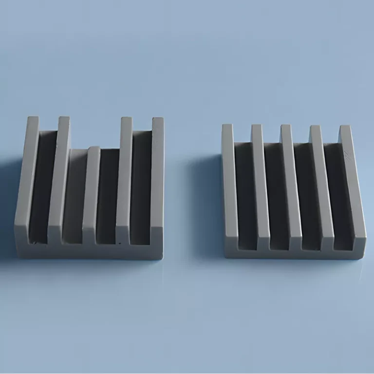
- Geometry flexibility: Flat/curved/tiled layouts, drilled holes, chamfered edges, and bond-ready finishes.
- Batch consistency: Controlled thickness tolerance and surface finish for repeatable installation.
Boron Carbide Plate Properties
|
B₄C Propertites |
|
|
Hot Pressed Sintered B4C |
|
Purity of B₄C |
≥90 |
|
Flexture strength (MPa) |
480 |
|
Elastic Modulus (GPa) |
450 |
|
Poisson's ratio |
0.21 |
|
Compressive strength (MPa) |
2500 |
|
Hardness (GPa) |
≥24 |
|
Fracture toughness (MPa*m1/2) |
4 |
|
Maximum working temperature (℃) |
1600 |
|
Thermal conductivity (W/m*K) |
150 |
|
Thermal expansion coefficient (/℃) |
4.4*10-6 |
|
Thermal shock resistance (ΔT ℃) |
400 |
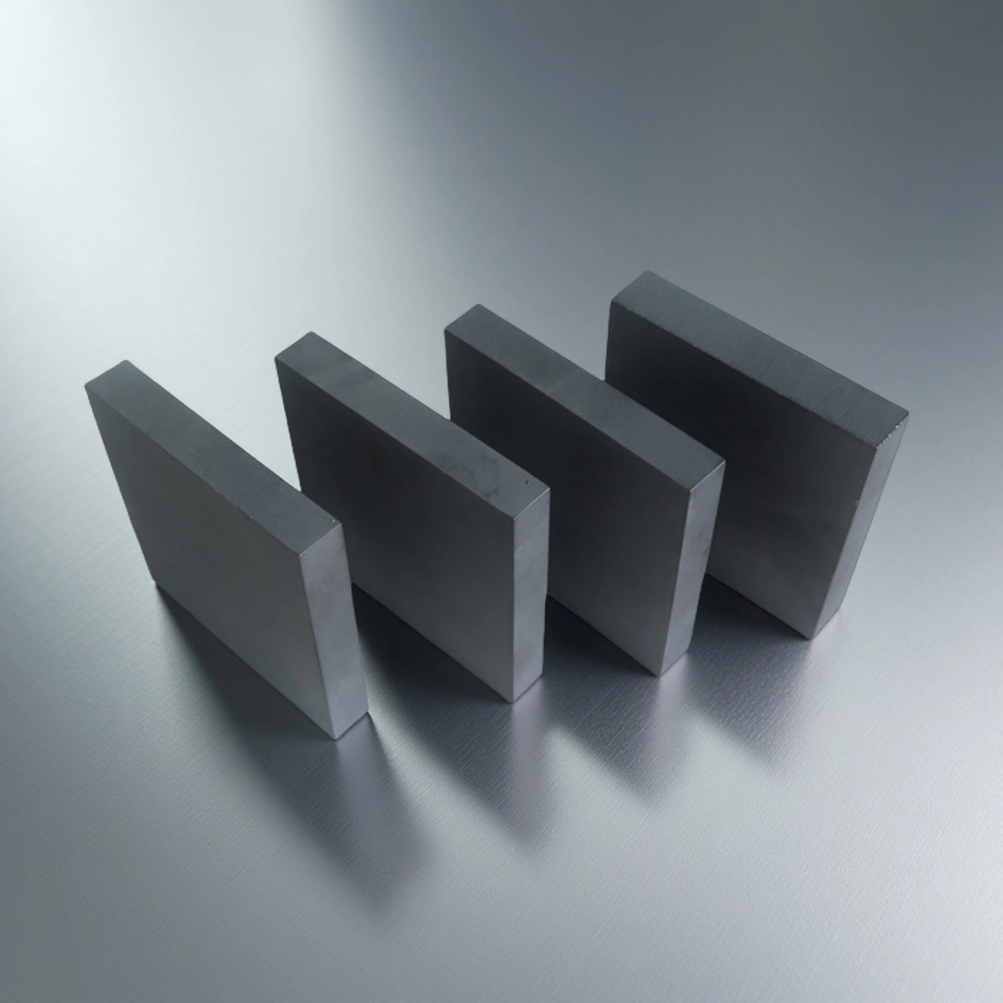
Specifications of Boron Carbide Plates
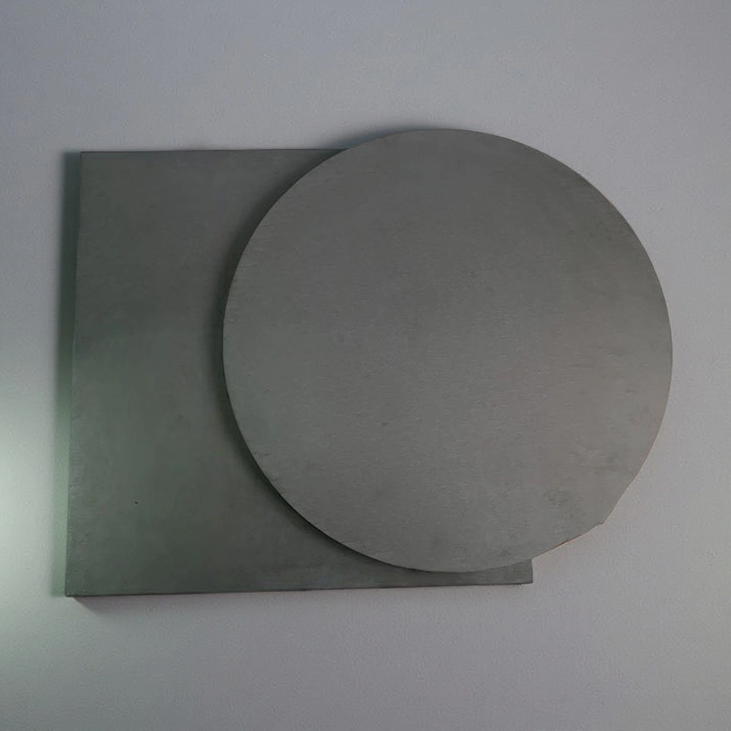
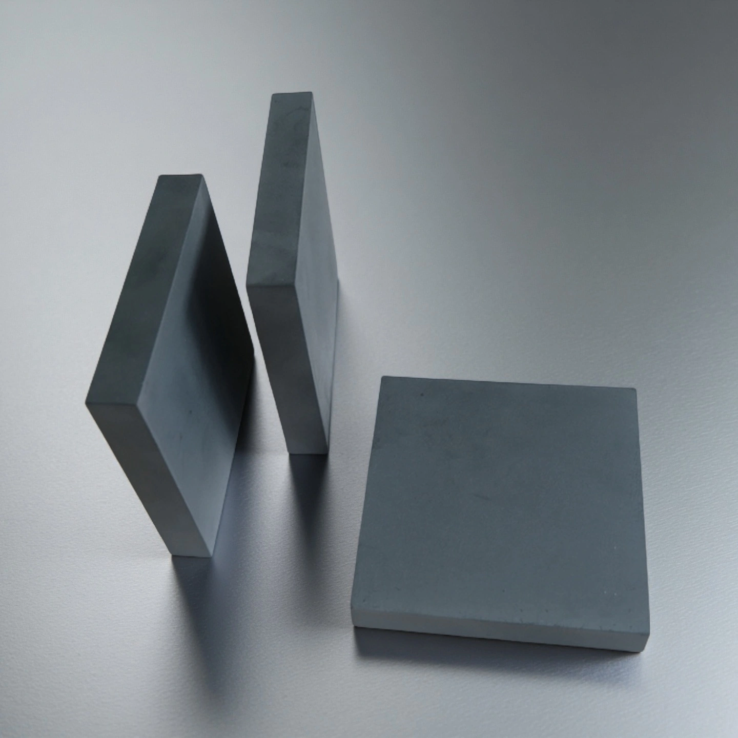
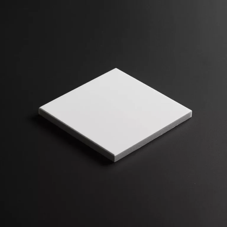
Type 1-Square B4C Plate

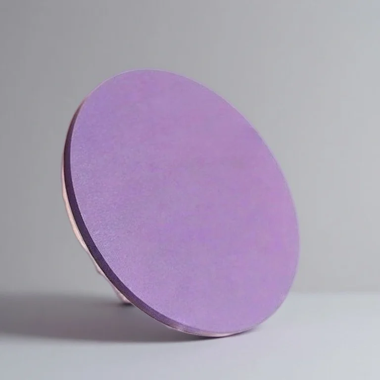
Type 2-Round B4C Plate

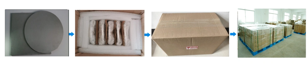
Boron Carbide Ceramic Plates Packaging
- Each plate is wrapped with PE foam and placed in a plywood box with corner protection.
Boron Carbide Plate Flat Usage Instructions
Proper installation and maintenance of boron carbide plates (B₄C plates) are essential to achieve full service life and dimensional stability in industrial systems. Follow the steps below to minimize stress, avoid micro-cracks, and maintain consistent performance over time.
-
Installation
1. Check flatness of the mounting surface using a feeler gauge or optical flat. Ensure deviation ≤ 0.1 mm over 100 mm length.
2. Use even adhesive films or elastic pads to buffer localized stress between the ceramic and base material.
3. For drilled plates, use torque-controlled fastening with washers or bushings to prevent edge stress.
4. When bonding, apply a thin uniform adhesive layer (0.1–0.3 mm); remove trapped air bubbles before curing.
5. Avoid direct metal-to-ceramic contact—introduce rubber or polymer interlayers to absorb vibration.
6. For curved or tiled assemblies, align gaps evenly (≤ 0.2 mm) to prevent stress accumulation.
-
Operation
1. Maintain gradual heating and cooling rates (< 10 °C/min) to prevent thermal shock or microcracking.
2. Do not expose plates to rapid temperature gradients or direct flame impingement.
3. Avoid impact loading and edge collision; install guards, liners, or protective covers near high-motion zones.
4. In continuous process lines, monitor pressure pulsations and vibration that could cause fatigue cracking.
5. For adhesive-mounted plates, re-torque or visually inspect every 6–12 months to ensure bond integrity.
-
Storage
1. Store in a dry, dust-free, and vibration-free environment (relative humidity < 60 %).
2. Keep plates in original foam cavities and sealed poly bags to prevent moisture absorption or surface abrasion.
3. Stack horizontally on flat shelves with soft interleaves between layers to avoid edge pressure.
4. Clearly label material grade, batch number, and dimension for traceability and re-order consistency.
5. Avoid long-term exposure to sunlight or high humidity, which may degrade packaging and identification labels.
-
Cleaning
1. Use lint-free cloths and isopropanol for surface cleaning before bonding or inspection.
2. Avoid abrasive pads or hard scrubbing tools that could create micro-surface scratches.
3. For stubborn residue, use ultrasonic cleaning with neutral pH solution for ≤ 5 minutes, followed by air drying.
4. When bonded, always follow adhesive manufacturer guidelines for solvent compatibility to protect bond lines.
5. Inspect bonding surfaces visually under proper lighting to ensure no residue, cracks, or delamination before reuse.
-
Common Issues & Fixes
1. Edge Chipping
Symptoms: micro-fractures or small chips along plate edges after mounting.
Cause: excessive torque, sharp metal contact, or uneven surface support.
Fix: add rubber spacers, use chamfered or radiused edges, and avoid direct metal-to-ceramic pressure points.
2. Adhesive Failure
Symptoms: partial debonding, visible air pockets, or uneven adhesion lines.
Cause: surface contamination, improper curing temperature, or excessive bond thickness.
Fix: re-prepare surfaces with light sandblasting or solvent cleaning, control adhesive thickness ≤ 0.3 mm, and follow recommended curing schedule.
3. Thermal Cracking
Symptoms: hairline fractures or audible cracking noise during heating or cooling.
Cause: fast temperature ramp rate or differential expansion with base materials.
Fix: maintain controlled ramp/soak profiles, add expansion gaps or elastic backings when different coefficients of thermal expansion (CTE) exist.