Process-Steady Silicon Carbide Cold Air Pipe for Thermal-Cycle Manufacturing Lines
The Silicon Carbide Cold Air Pipe is engineered to deliver stable performance under rapid thermal cycling, oxidizing kiln atmospheres, and long-duration furnace operations, and its material system supports measurable improvements in thermal integrity, mechanical reliability, and chemical resistance across industrial environments.
Catalogue No.
AT-THG-LFG001
Material
RB-SiC / R-SiC
Thermal Shock Resistance
Withstands temperature differences exceeding 1000 °C per cycle
ADCERAX® Silicon Carbide Cold Air Pipe is engineered for roller kiln cooling zones where rapid temperature transitions and continuous airflow demand stable thermal and structural performance. Its RB-SiC or R-SiC microstructure provides thermal shock resistance, oxidation stability, and long-term mechanical strength under high-temperature cycling. These material characteristics support reliable cooling control across extended industrial operations, ensuring consistent performance in ceramic, metallurgical, and thermal-processing environments.
Key Performance Features of Silicon Carbide Cold Air Pipe
Low Thermal Expansion Stability The material maintains dimensional stability with a coefficient of thermal expansion below 4.5×10⁻⁶ K⁻¹, limiting stress accumulation during temperature swings. This enables consistent airflow performance even when cooling gradients exceed 300 °C/min in roller kiln zones.
High Thermal Shock Endurance Field evaluations indicate that SiC components resist thermal shock events where temperature differences exceed 1000 °C in a single cycle. This stability prevents cracking or micro-fracture formation under aggressive cooling airflow.
Enhanced Heat Dissipation Efficiency The high thermal conductivity of RB-SiC, typically above 20 W/m·K, supports rapid surface heat extraction during kiln cooling sequences. This accelerates recovery between firing cycles and improves stability of downstream temperature profiles.
High Oxidation Resistance SiC surface oxidation rates remain below 1 mg/cm² even after 200 h at elevated temperatures in oxidizing air. This prevents scaling that commonly disrupts airflow in metallic components.
Corrosion Resistance in Kiln Atmospheres The non-reactive SiC matrix resists attack from kiln gases containing volatile oxides and process by-products with measured degradation below 0.2% after extended exposure. This ensures stable airflow pathways in ceramic and thermal-processing systems.
Surface Stability for Airflow Consistency Long-term kiln operation tests show less than 2% change in internal surface roughness after continuous cycling. This stability maintains predictable airflow distribution and reduces turbulence-related thermal fluctuations.
Technical Specifications of Silicon Carbide Cold Air Pipe
ADCERAX® Silicon Carbide Cold Air Pipe is defined by its stable thermal behavior, high mechanical integrity, and oxidation-resistant SiC matrix, enabling consistent performance under long-term high-temperature cycling and aggressive kiln atmospheres.
Property
Specification
Material Composition
RB-SiC / R-SiC, β-SiC dominant phase
Density
≥ 2.95 g/cm³
Thermal Conductivity
≥ 20 W/m·K
Thermal Expansion Coefficient
≤ 4.5×10⁻⁶ K⁻¹
Maximum Continuous Service Temperature
Up to 1600 °C
Flexural Strength
≥ 250 MPa
Elastic Modulus
≥ 350 GPa
Hardness
≥ 90 HRA
Oxidation Resistance
Mass gain ≤ 1 mg/cm² (200 h exposure)
Creep Resistance
Deformation rate ≤ 0.5% at high temperature
Porosity
≤ 1% closed porosity
Thermal Shock Endurance
Withstands ΔT ≥ 1000 °C per cycle
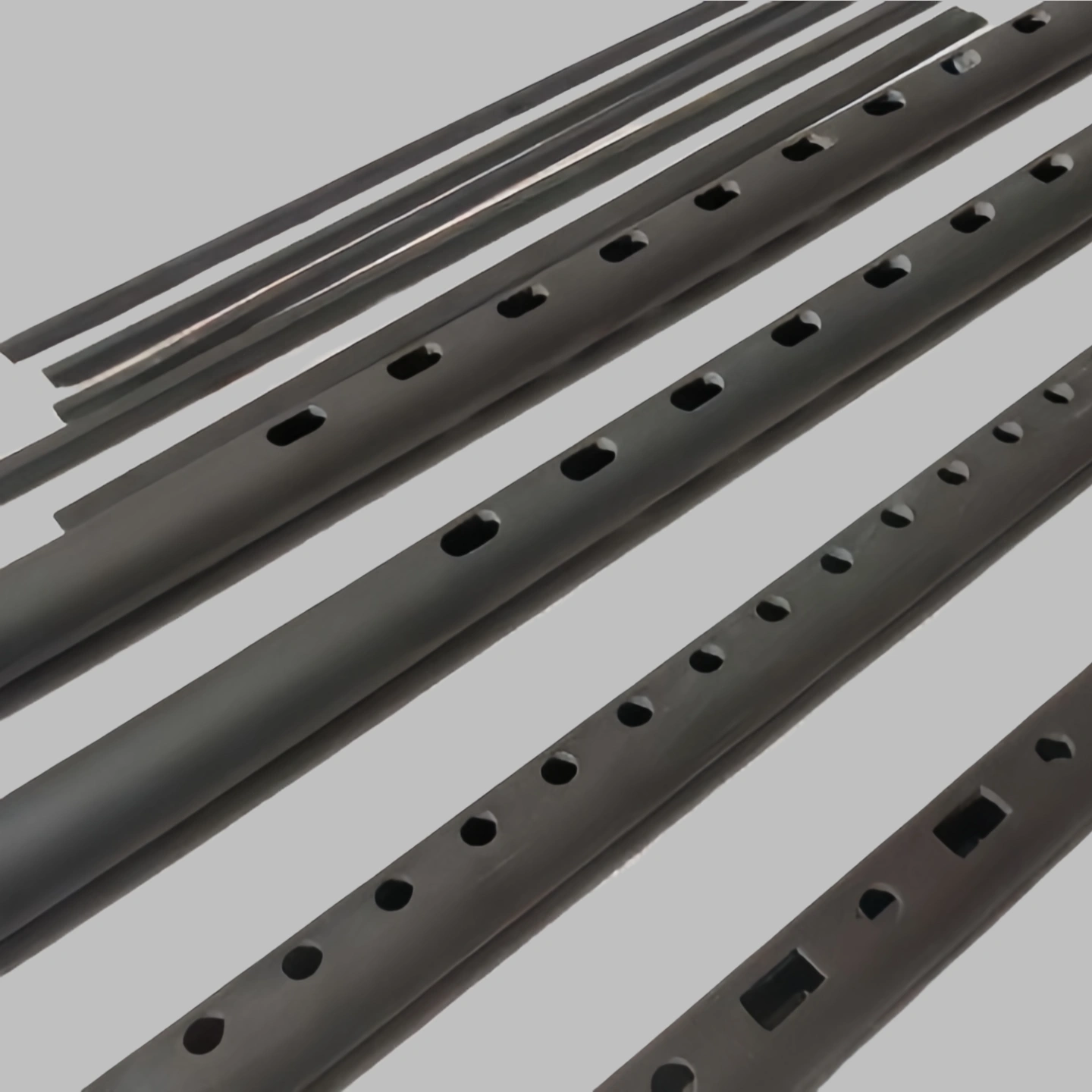
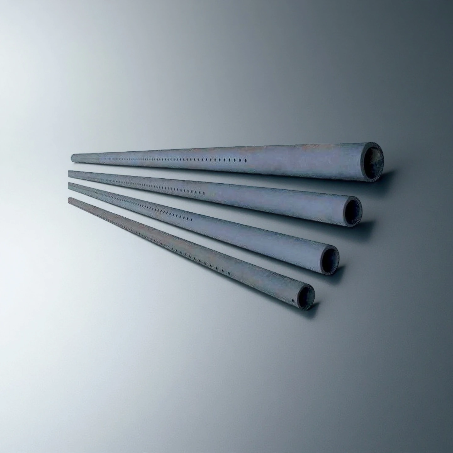
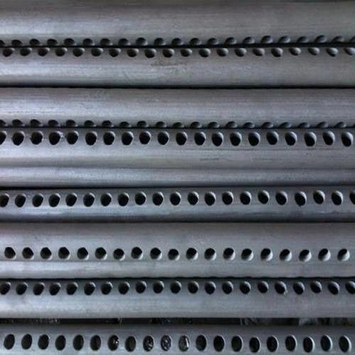
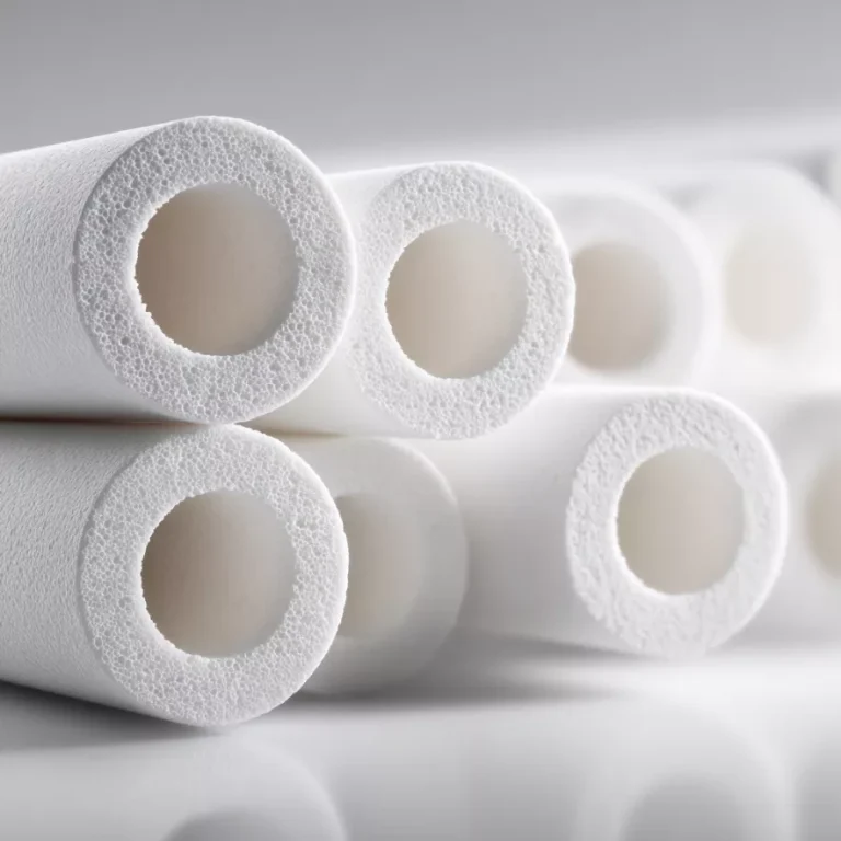
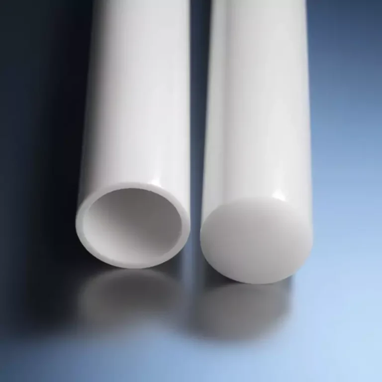
Dimensions of Silicon Carbide Cold Air Pipe
SiC Cold Air Pipe
Item No.
Outer Diameter (mm)
Inner DIameter (mm)
Thickness (mm)
Length (mm)
AT-THG-LFG001
40
30
5
50-4000mm
AT-THG-LFG002
42
32
5
AT-THG-LFG003
42
30
6
AT-THG-LFG004
45
35
5
AT-THG-LFG005
45
33
6
AT-THG-LFG006
45
31
7
AT-THG-LFG007
48
38
5
AT-THG-LFG008
48
36
6
AT-THG-LFG009
48
34
7
AT-THG-LFG010
50
40
5
AT-THG-LFG011
50
38
6
AT-THG-LFG012
50
36
7
AT-THG-LFG013
55
43
6
AT-THG-LFG014
55
39
8
AT-THG-LFG015
58
46
6
AT-THG-LFG016
58
44
7
AT-THG-LFG017
58
42
8
AT-THG-LFG018
60
48
6
AT-THG-LFG019
60
46
7
AT-THG-LFG020
60
44
8
AT-THG-LFG021
65
51
7
AT-THG-LFG022
65
53
6
AT-THG-LFG023
70
58
6
AT-THG-LFG024
70
56
7
AT-THG-LFG025
70
54
8
AT-THG-LFG026
75
57
9
AT-THG-LFG027
75
55
10
AT-THG-LFG028
80
60
10
AT-THG-LFG029
80
58
11
AT-THG-LFG030
80
56
12
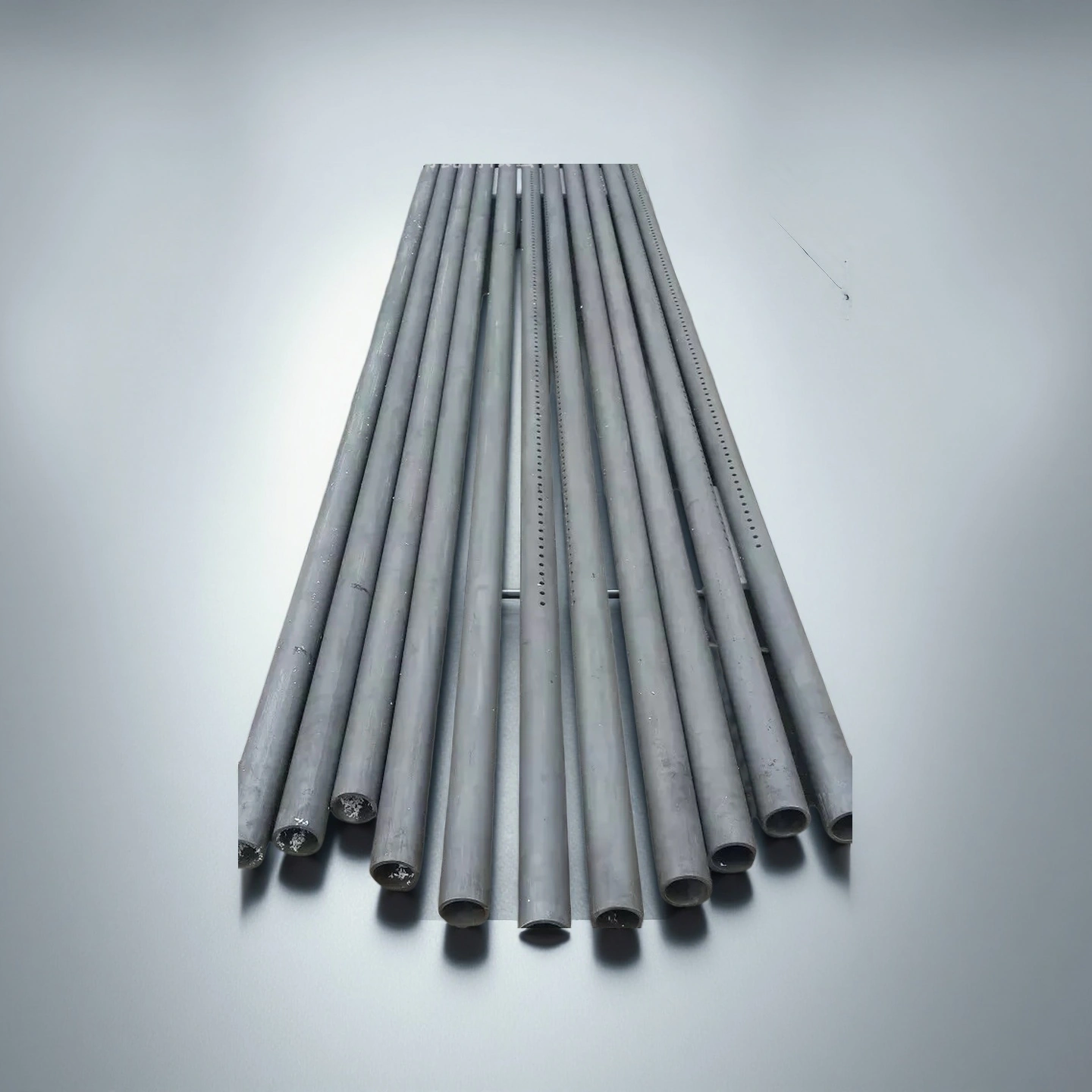
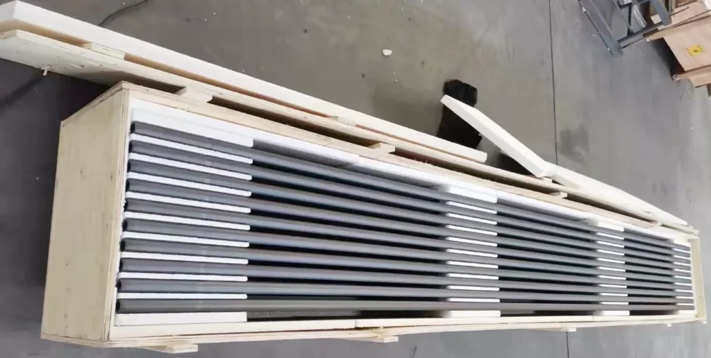
Packaging for Silicon Carbide Cold Air Pipe
Silicon Carbide Cold Air Pipe is securely packed in reinforced wooden crates designed to withstand long-distance industrial transport. Each pipe is individually separated with foam partitions to prevent abrasion, impact, or surface damage during handling. The final crate structure ensures stable positioning of all components, maintaining product integrity from factory dispatch to end-user installation.
ADCERAX® Silicon Carbide Cold Air Pipe Resolves Critical Thermal-Cycle Challenges in Industrial Kiln Cooling Systems
ADCERAX® Silicon Carbide Cold Air Pipe is applied in high-demand cooling environments where rapid thermal cycling, oxidizing kiln atmospheres, and long-duration mechanical loading must be controlled simultaneously. This section analyzes three specific industry scenarios in which these pipes eliminate persistent reliability failures, improve production continuity, and reduce total lifecycle cost.
Silicon Carbide Cold Air Pipe in Roller Kiln Cooling Zones for Daily-Use and Sanitary Ceramics
✅Key Advantages
1. High-Gradient Thermal Stability ADCERAX® Silicon Carbide Cold Air Pipe remains structurally stable when ware exits firing temperatures above 1100 °C and enters rapid cooling segments. Even under cooling ramps exceeding 300 °C/min, the pipe maintains straightness and airflow geometry.
2. Low Defect Impact on Glazed Surfaces By keeping airflow distribution uniform along the kiln axis, the pipe helps reduce glaze-related defects that previously arose from distorted or scaled metal tubes. Plants switching to SiC have reported visible defect rates dropping from around 7% to below 3% during high-throughput operation.
3. Extended Service Life Under Multi-Shift Operation The SiC matrix withstands repeated thermal-shock cycles far beyond the limits of stainless steel or quartz tubes. In multi-shift continuous firing, service life has been observed at more than 10× that of conventional metal tubes, cutting the frequency of unplanned replacements.
✅ ️Problem Solved
A daily-use and sanitaryware plant operating three shifts reported that stainless steel cooling tubes began to deform after approximately 6–9 months, causing airflow imbalance and pushing glaze defect rates above 8% during peak production. Frequent scaling and cracking forced unplanned stoppages of 4–6 hours each time maintenance replaced damaged tubes. After introducing ADCERAX® Silicon Carbide Cold Air Pipe into the roller kiln cooling zone, tube replacement intervals extended beyond 4 years, and glaze defect rates stabilized around 2–3%. Conveyor speeds could be increased by about 10–15% without sacrificing cooling stability, restoring predictable output across continuous firing cycles.
Silicon Carbide Cold Air Pipe in Magnetic Material & Ferrite Component Sintering Lines
✅Key Advantages
1. Controlled Cooling for Magnetic Property Stability ADCERAX® Silicon Carbide Cold Air Pipe supports tightly controlled cooling ramps needed to maintain ferrite permeability and coercivity within specification windows. Plants have reported that peak-to-peak temperature variation at the cooling outlet fell by more than 25% after replacing alumina and metal tubes with SiC pipes.
2. Reduced Thermal-Shock Breakage in Long Sintering Cycles The SiC structure withstands rapid cold-air injection without the fracture events commonly seen in alumina or metallic tubes during sintering cycles lasting 6–12 hours. This resilience has helped cut tube-related line interruptions by over 50% in continuous ferrite production.
3. Stable Flow Path for Consistent Furnace Uptime With low creep deformation (below 0.5% under long-term elevated temperature), the pipe maintains an open and stable airflow channel throughout extended campaigns. This stability directly supports furnace uptimes above 90–95% of planned operating hours in many magnetic material lines.
✅ ️Problem Solved
A ferrite component manufacturer running continuous sintering cycles of 8 hours per batch experienced alumina tube fractures roughly once every 2–3 weeks, each event forcing an emergency shutdown and causing partial or full batch rejection. Cooling non-uniformity during these incidents contributed to off-spec magnetic properties in up to 12–15% of affected production. After replacing the cooling section with ADCERAX® Silicon Carbide Cold Air Pipe, tube-related fracture incidents were reduced to fewer than two per year, and off-spec rates linked to cooling instability dropped below 4%. Furnace availability increased by approximately 8–10 percentage points, and energy waste tied to aborted cycles was significantly reduced.
Silicon Carbide Cold Air Pipe in Building Ceramic Tile Lines and Fast-Cooling Thermal-Processing Equipment
✅Key Advantages
1. Dimensional Flatness Support at High Throughput ADCERAX® Silicon Carbide Cold Air Pipe maintains a rigid airflow channel when tile lines operate at elevated conveyor speeds to meet seasonal demand. Production data from upgraded lines indicate curvature-related flatness defects falling from about 6% to below 2.5% once SiC replaced deformed stainless steel tubes.
2. Resistance to Collapse Under High Air Velocity The combination of flexural strength above 250 MPa and elastic modulus exceeding 350 GPa prevents collapse when airflow velocity is increased for faster cooling. This allows operators to raise cooling-air volume by 20–30% without triggering tube distortion that would disrupt temperature profiles.
3. Long-Term Stability in Oxidizing Furnace Atmospheres The oxidation-resistant SiC matrix limits surface change to less than 2% roughness variation after extended cycling, even in high-oxygen environments. This preserves cooling efficiency and avoids the sharp drops in heat extraction seen when scaled metal tubes restrict flow areas.
✅ ️Problem Solved
A building-ceramic tile producer operating continuous lines at high capacity reported that stainless steel and quartz cooling tubes began to warp or crack whenever airflow was increased to shorten cooling time, leading to curvature defects on more than 5–7% of tiles in peak seasons. Each tube-collapse event triggered line stoppages lasting 3–5 hours, with maintenance and scrap costs escalating across the year. After installing ADCERAX® Silicon Carbide Cold Air Pipe in the fast-cooling section, the plant raised airflow by around 25% while keeping tile flatness within tolerance, and curvature-related defects dropped to below 3%. Unplanned downtime linked to cooling tube failure was reduced by more than 60%, allowing the line to sustain higher seasonal throughput with more predictable maintenance planning.
ADCERAX® Silicon Carbide Cold Air Pipe User Guide for Stable, Safe, and Long-Cycle Operation
The Silicon Carbide Cold Air Pipe requires proper handling, installation, and operational management to achieve stable airflow performance, maintain mechanical integrity, and support long-cycle furnace operation in high-temperature cooling environments.
Installation Preparation and Handling Requirements
1. Inspection Before Installation All pipes should be visually checked for surface cracks, edge chips, or contamination prior to assembly. Any irregularities can affect airflow uniformity during initial startup. A clean, undamaged surface ensures consistent thermal-shock performance under rapid cooling.
2. Safe Lifting and Transport Each pipe must be supported along its full length and handled with soft-contact lifting tools. Avoiding point-load pressure prevents structural stress concentration during installation. Controlled movement reduces the chance of accidental impact or dropping in confined kiln-line spaces.
3. Environmental Cleanliness During Setup The mounting area should remain free of abrasive particles or metal fragments that may scratch the SiC surface. Contamination can increase friction and turbulence inside the airflow channel. Ensuring a clean environment protects long-term pipeline stability and airflow consistency.
Integration Into Cooling Systems and Alignment Control
1. Precise Alignment With Air Distribution Manifolds Misalignment can cause uneven airflow distribution, reducing cooling uniformity along the roller kiln exit. Using calibrated fixtures ensures the pipe axis remains parallel to the airflow pathway. Proper alignment also prevents structural loading at the pipe ends.
2. Thermal Expansion Considerations All support interfaces should provide controlled clearance so the pipe can accommodate thermal movement during heating and cooling cycles. Restricting expansion may induce stress points under rapid cooling conditions. Allowing free expansion ensures stable geometry throughout operation.
3. Securing Connections for Continuous Vibration Exposure Cooling zones often experience vibration from fans and roller movement. Firm yet flexible mounting prevents micro-shifts that lead to misdirected airflow. Stable support structures reduce long-term fatigue and preserve consistent cooling performance.
Operational Management for Optimal Cooling Performance
1. Airflow Cleanliness and Monitoring Compressed or forced air should be filtered to remove hard particulates that may erode the inner wall. Clean airflow reduces abrasion and preserves the internal surface finish over extended cycles. Regular filter changes help maintain long-term cooling stability.
2. Avoiding Excessive Cooling Intensity During Start-Up Introducing high-velocity cold air before kiln temperature equalizes can increase thermal stress on ceramic or product surfaces. Gradually increasing airflow avoids sudden thermal gradients across the pipe. Controlled ramp-up protects both the cooling system and downstream product quality.
3. Routine Temperature Distribution Checks Periodic monitoring of cooling-zone temperatures ensures the pipe is operating within its intended thermal envelope. Detecting deviations early prevents hot-spot formation and downstream product defects. Stable temperature distribution indicates healthy airflow through the system.
Maintenance Planning and Long-Cycle Service Protection
1. Scheduled Surface Integrity Inspections External and internal surfaces should be inspected for oxidation deposits or micro-abrasion marks at defined intervals. Early identification helps prevent long-term airflow restriction. Maintaining surface quality supports predictable cooling behavior through continuous cycles.
2. Cleaning Procedures for Long Service Life Deposits should be removed using non-metallic tools to avoid scratching the SiC structure. Gentle brushing or air-pulse cleaning preserves the pipe’s inner geometry. Regular cleaning ensures consistent thermal-exchange efficiency.
3. Replacement Strategy for Multi-Shift Operations A proactive replacement schedule reduces unexpected downtime in continuous firing plants. Tracking service hours helps forecast pipe longevity accurately. Predictable replacement planning reduces maintenance costs and supports stable production output.
Technical FAQs Addressing Real-World Engineering Challenges with ADCERAX® Silicon Carbide Cold Air Pipe
Q1: How does the Silicon Carbide Cold Air Pipe maintain stability under rapid temperature drops in roller kiln cooling zones?
The Silicon Carbide Cold Air Pipe withstands extreme thermal-shock events because its RB-SiC/R-SiC matrix has a thermal expansion coefficient below 4.5×10⁻⁶ K⁻¹. This prevents microcracking when cold air is injected against ware exiting firing temperatures above 1100 °C. Continuous cooling ramps exceeding 300 °C/min are tolerated without structural distortion. These properties ensure consistent airflow geometry across long production cycles.
Q2: Why is the Silicon Carbide Cold Air Pipe more resistant to oxidation than metal cooling tubes?
The Silicon Carbide Cold Air Pipe features a covalent SiC lattice that forms a thin, stable silica layer under oxidizing conditions. This layer limits mass-gain to below 1 mg/cm² even after prolonged exposure. Unlike steel, it does not form scale that clogs or narrows airflow channels. This oxidation stability directly supports long-term temperature uniformity in kiln cooling zones.
Q3: How does the Silicon Carbide Cold Air Pipe prevent airflow distortion during high-capacity operation?
Its elastic modulus above 350 GPa ensures the pipe maintains straightness even under heavy mechanical loading. This rigidity prevents bending that would otherwise deflect airflow and create cold-spot patterns. By preserving its geometry, the Silicon Carbide Cold Air Pipe supports stable temperature gradients at high conveyor speeds. This directly reduces defect rates in ceramics, tiles, and ferrite components.
Q4: What makes the Silicon Carbide Cold Air Pipe suitable for repeated thermal-cycling in continuous firing lines?
SiC’s creep deformation rate remains below 0.5% after extended high-temperature operation. This allows the Silicon Carbide Cold Air Pipe to maintain dimensional accuracy during thousands of heating–cooling cycles. Unlike metal tubes that progressively distort, SiC preserves its internal flow path. This characteristic is essential for multi-shift ceramic plants with minimal downtime windows.
Q5: How does the Silicon Carbide Cold Air Pipe reduce glaze-defect formation in sanitaryware and tableware kilns?
Because the pipe maintains a stable cross-section at high temperatures, airflow across the cooling zone stays consistent. This prevents the glaze deformation and surface waviness associated with fluctuating temperature profiles. The Silicon Carbide Cold Air Pipe minimizes thermal shock at the critical transition from firing to cooling. The result is reduced visible defects during high-throughput operation.
Engineering Evaluations of ADCERAX® Silicon Carbide Cold Air Pipe in High-Demand Kiln Cooling Systems
⭐️⭐️⭐️⭐️⭐️
“Our firing line experienced repeated cooling instability until we integrated the Silicon Carbide Cold Air Pipe into the roller-kiln outlet. The component maintained consistent airflow alignment even during aggressive cooling ramps. We observed a marked reduction in glaze deformation events, and our multi-shift operation became far more predictable. The pipe’s long-cycle dimensional stability removed a major bottleneck in our production schedule.”
— M. Turner, Process Engineering Division, North Atlantic Ceramics Group
⭐️⭐️⭐️⭐️⭐️
“In our ferrite sintering plant, alumina tubes fractured frequently and disrupted long thermal-cycle programs. After switching to the Silicon Carbide Cold Air Pipe, the cooling curve became far more stable and temperature deviation at the outlet dropped by over 20%. This directly reduced magnetic-property drift across batches and improved furnace availability. It has become a dependable component in a demanding, continuous-run environment.”
— L. Schneider, Materials Engineering Department, EuroMag Components GmbH
⭐️⭐️⭐️⭐️⭐️
“Our tile-line cooling zone required higher airflow volume to support seasonal throughput increases, but metal tubes collapsed under the load. The Silicon Carbide Cold Air Pipe sustained the elevated flow rate with no deformation over several months of high-capacity operation. Flatness-related defects decreased significantly, and the cooling stage became far more controllable. The upgrade provided measurable gains in output and line reliability.”
— D. Williams, Thermal Systems Engineering, Western Stone & Tile Manufacturing
⭐️⭐️⭐️⭐️⭐️
“The cooling section of our high-temperature processing equipment previously suffered from inconsistent airflow due to oxidation and scaling on steel pipes. Integrating the Silicon Carbide Cold Air Pipe eliminated those issues, and its oxidation-stable surface finish kept our temperature profile uniform across long production runs. Maintenance frequency dropped sharply, and the overall furnace cycle became more repeatable.”
— S. Yamamoto, Equipment Reliability Group, Kyushu Industrial Materials Lab
ADCERAX® Silicon Carbide Cold Air Pipe is supported with engineering-oriented customization options designed to align with diverse kiln cooling architectures and demanding thermal-cycle conditions.
Geometry and Structural Configuration Customization
Adaptations are enabled to match varied cooling-zone layouts and mechanical integration requirements.
Outer Shape Options Provided to accommodate different mounting structures.
Internal Channel Form Adjusted to support airflow distribution control.
End-Connection Style Aligned to interface with multiple airflow manifolds.
Material Composition and Microstructure Tuning
Modifications are applied to ensure targeted thermal-shock stability and oxidation resistance for specific firing environments.
RB-SiC Selection Optimized for stable thermal-cycle endurance.
R-SiC Variant Applied to improve creep and oxidation behavior.
Surface Density Control Used to enhance strength under prolonged heating.