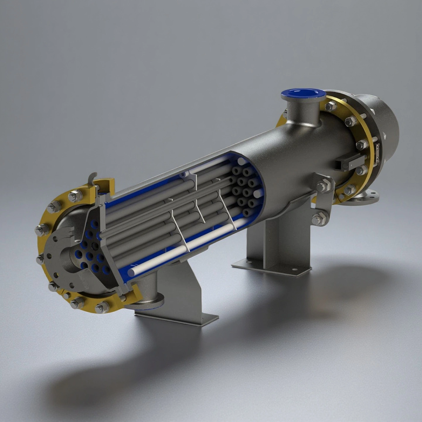
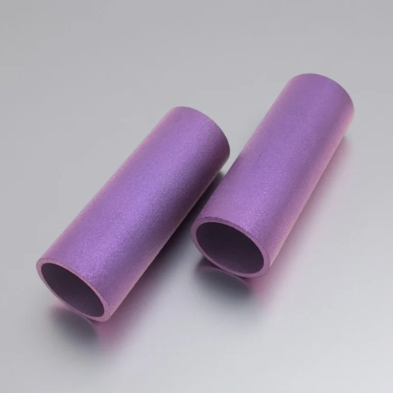
ADCERAX® Silicon Carbide Heat Exchanger Tubes are engineered using interlocked square air channels and rectangular flue-gas channels that form a stable dual-layer cross-flow structure designed for long-term operation in corrosive heat-recovery systems. The bonded SiC channel network, reinforced with L-shaped ceramic seals and a steel housing filled with aluminosilicate insulation, maintains structural integrity under thermal shock, vibration, and acidic condensate exposure. This configuration delivers stable flow behavior, high mechanical strength, and reliable leak-free performance, making it well suited for industrial furnace flue-gas recovery and other energy-efficient process applications.
Key Performance Features of Silicon Carbide Heat Exchanger Tube
-
Corrosion Stability
Testing in HF, HCl and mixed acid streams shows mass-loss rates consistently below 0.1%, ensuring predictable long-term operation.
This stability enables continuous use in chemical lines where metal equipment typically fails within 3–6 months.
-
Media Compatibility
The non-porous SSiC microstructure (open porosity < 0.1%) prevents penetration of halogenated or oxidizing compounds.
This characteristic reduces contamination risk in high-purity processes requiring media integrity above 99.9%.
-
Service-Life Improvement
Field data from acid-processing facilities indicate service-life extension by 2–5× compared with graphite exchangers.
This directly lowers annual maintenance budgets by 30–55%, particularly in continuous high-corrosion production lines.
-
Thermal Conductivity
SSiC materials provide thermal conductivity of 120–150 W/m·K, far exceeding stainless steel or titanium alternatives.
This increased heat-transfer efficiency enables faster temperature stabilization in chemical and flue-gas systems.
-
Reduced Exchange Area
Compared with glass-lined equipment, SiC tubes can reduce required heat-exchange area by up to 70%.
This reduction decreases installation footprint and allows system upgrades without major structural modifications.
-
Thermal Shock Reliability
Tests under ΔT cycles above 250°C show no cracking or deformation of the SiC channel network.
This resistance supports safe operation in fast heating–cooling cycles common in flue-gas recovery units.
-
Mechanical Strength
SSiC materials exhibit flexural strength exceeding 350 MPa, providing rigidity under continuous flow vibration.
This resilience ensures stable operation in systems with high gas velocities and particulate loading.
-
Seal Performance
L-shaped ceramic seals and bonded joints demonstrate leakage rates below 0.01%, even under pressure fluctuations.
This supports long-term reliability where traditional ceramic plate exchangers often experience early seal failures.
-
Downtime Reduction
Plants using SiC tube modules report maintenance-related downtime reduced by 40–60% over five-year operation periods.
Reduced cleaning cycles and improved seal durability significantly lower unplanned interruption frequency.
Technical Specifications of Silicon Carbide Heat Exchanger Tube
ADCERAX® Silicon Carbide Heat Exchanger Tubes are engineered for stable performance under high-corrosion, high-thermal-load, and high-purity operating environments, combining dense SiC microstructure, strong thermal conduction, and reliable mechanical integrity required for demanding industrial heat-exchange systems.
| Property |
Specification |
| Material Type |
SSiC / RSiC |
| Density |
> 3.10 g/cm³ |
| Open Porosity |
< 0.1% |
| Thermal Conductivity |
120–150 W/m·K |
| Thermal Expansion Coefficient |
4.0–4.5 × 10⁻⁶ /K (25–1000°C) |
| Flexural Strength |
> 350 MPa |
| Compressive Strength |
> 2200 MPa |
| Hardness |
> 2500 HV10 |
| Maximum Operating Temperature |
Up to 220°C (application-dependent) |
| Chemical Stability |
Resistant to HF, HCl, H₂SO₄, HNO₃, NaOH, Br₂, Cl₂ |
| Oxidation Resistance |
Stable to > 1000°C in oxidizing atmospheres |
| Thermal Shock Resistance |
ΔT ≥ 250°C class |
| Electrical Resistivity |
> 10⁵ Ω·cm |
| Acid Solubility |
< 0.02 mg/cm² after 48 h immersion |
| Surface Roughness |
≤ 1.0 μm Ra (inner channel walls) |
Dimensions of Silicon Carbide Heat Exchanger Tube
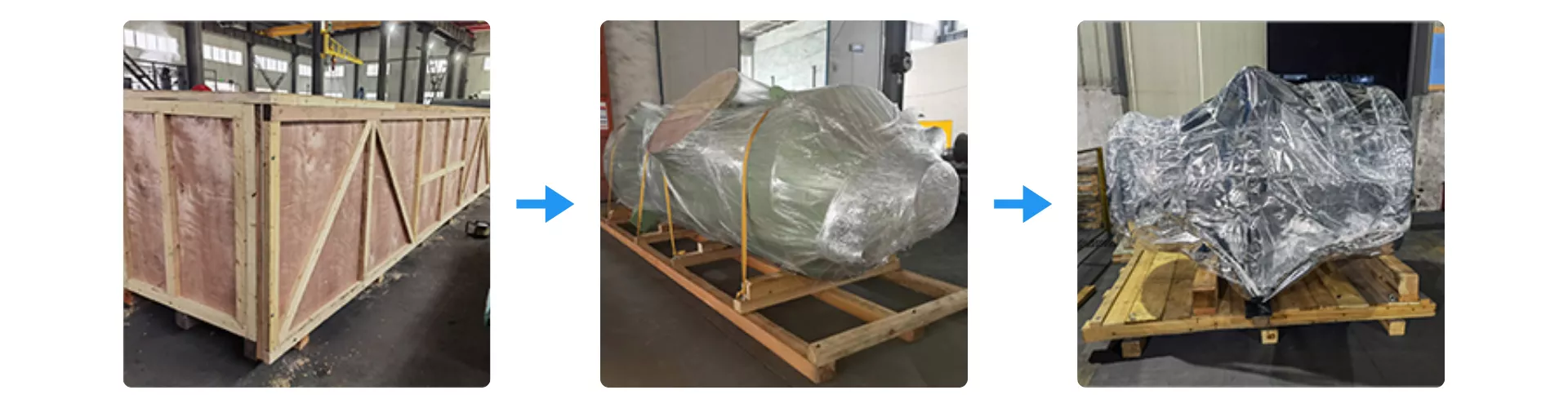
Packaging Process for Silicon Carbide Heat Exchanger Tubes
Silicon Carbide Heat Exchanger Tubes are secured using reinforced wooden crating to protect the module during long-distance international transport. Each unit is wrapped with multi-layer moisture-barrier film and fixed onto a vibration-resistant wooden base to prevent structural stress. The exterior crate is further sealed and braced to ensure safe handling during loading, unloading, and maritime shipment.
ADCERAX® Silicon Carbide Heat Exchanger Tubes Resolve Critical Process Challenges in Corrosive and High-Load Industrial Systems
ADCERAX® Silicon Carbide Heat Exchanger Tubes address the operational failures, corrosion limits, and thermal-load constraints commonly encountered in chemical processing, fine-chemical synthesis, metallurgical pickling, and flue-gas energy-recovery equipment. Their multi-channel SiC architecture, high corrosion stability, and structural integrity directly target the reliability gaps and contamination risks that conventional metal, glass-lined, or graphite exchangers cannot withstand.
-
Silicon Carbide Heat Exchanger Tubes in Bromine-Based Chemical Cooling and Condensation Systems
✅Key Advantages
1. Halogen-stable SiC channel network: In bromine and HBr media, ADCERAX® Silicon Carbide Heat Exchanger Tubes show mass-loss rates below 0.1% after 1,000 h exposure in laboratory corrosion tests. This stability contrasts with graphite modules that typically lose 5–10% of strength in comparable halogen environments.
2. Low-porosity structure for purity control: The dense SSiC microstructure with open porosity under 0.1% helps prevent bromine ingress and crack initiation along grain boundaries. This directly supports product purity levels above 99.9% where trace contamination from exchanger materials is not acceptable.
3. Stable heat removal under narrow temperature windows: Thermal conductivity in the 120–150 W/m·K range supports tight temperature control where process windows are often limited to ±3–5°C. This contributes to consistent conversion and impurity control in brominated intermediate production without oversizing the cooling surface.
✅ ️Problem Solved
A bromine-based fine chemical plant reported that graphite heat exchangers in its condensation section required replacement every 4–6 months, with each unplanned shutdown costing approximately USD 40k–60k in lost production and requalification. After switching to ADCERAX® Silicon Carbide Heat Exchanger Tubes with <0.1% porosity and halogen-stable SSiC, exchanger service life extended beyond 24 months without recorded leakage events. Temperature stability within ±3°C along the condenser section reduced off-spec batches by about 30%, and maintenance interventions on this line were cut by more than 50% over a two-year observation period.
-
Silicon Carbide Heat Exchanger Tubes in High-Acid Pickling and Metal Surface Treatment Lines
✅Key Advantages
1. Chloride-resistant load-bearing structure: In HCl and mixed-acid pickling baths, ADCERAX® Silicon Carbide Heat Exchanger Tubes maintain structural integrity where steel exchangers experience rapid wall thinning. Flexural strength above 350 MPa and compressive strength above 2200 MPa allow the tube bundles to withstand continuous recirculation loads without crack formation under chloride attack.
2. Stable performance at high flow velocity: The abrasion-resistant SiC surface and hardness above 2500 HV10 support operation at flow velocities exceeding 2–3 m/s with scale-laden fluids. This reduces the risk of localized erosion and channel deformation that would otherwise cause hot spots and uneven pickling.
3. Reduced blockage in particulate-rich circuits: The smooth internal channel finish, typically ≤1.0 μm Ra, and rigid geometry help limit sludge deposition in high-solids pickling loops. Plants can extend cleaning intervals from 3–4 months for graphite units to 9–12 months for SiC bundles without significant loss of heat-transfer efficiency.
✅ ️Problem Solved
In a high-acid steel pickling line operating with HCl at 80–90°C, conventional metal exchangers were failing within 3–5 months, and graphite units suffered clogging that forced shutdowns roughly 3 times per year. Each stoppage reduced weekly throughput by 8–10% and created maintenance costs in the range of USD 15k–25k per event. After installing ADCERAX® Silicon Carbide Heat Exchanger Tubes with hardness above 2500 HV10 and flexural strength above 350 MPa, the plant reported uninterrupted operation for 12 months with only scheduled flushing. Cleaning frequency was reduced by around 50%, and total heat-exchanger-related downtime on the line decreased by more than 40% over the first full year.
-
Silicon Carbide Heat Exchanger Tubes in Flue-Gas Heat Recovery for Industrial Furnaces and Kilns
✅Key Advantages
1. Thermal-cycle resistant cross-flow assembly: ADCERAX® Silicon Carbide Heat Exchanger Tubes tolerate repeated ΔT steps of ≥250°C common in furnace start–stop and load-change cycles. The bonded multi-channel structure avoids partition cracking that is frequently observed in plate-type ceramics exposed to rapid flue-gas temperature swings.
2. Erosion resistance in particulate-laden gas streams: With hardness above 2500 HV10 and dense SSiC channels, the tubes maintain geometry under dust-laden flue-gas velocities in the 10–20 m/s range. This helps stabilize airflow and pressure drop where softer materials lose cross-section from continuous particle impact.
3. Compact heat-recovery with reduced surface area: High thermal conductivity of 120–150 W/m·K allows comparable heat-recovery duty with up to 50–70% less exchange surface than glass-lined or low-conductivity designs. This enables retrofits in constrained furnace layouts while still achieving measurable reductions in fuel consumption.
✅ ️Problem Solved
A kiln-based ceramic manufacturer operating with flue-gas temperatures of 800–950°C and SOx/Cl-bearing exhaust reported that traditional ceramic plate exchangers developed cracks after 200–400 thermal cycles, leading to leakage and reduced heat-recovery efficiency. Fuel usage for the firing process increased by an estimated 8–12% during periods of degraded exchanger performance. After adopting ADCERAX® Silicon Carbide Heat Exchanger Tubes with documented ΔT resistance of ≥250°C and high erosion durability, the plant maintained stable heat recovery over more than 1,000 operating cycles without structural failure. Recorded fuel consumption for the same production volume dropped by approximately 6–9%, and maintenance intervals for the heat-recovery section were extended from semi-annual to annual inspections.
Operational Guidance for ADCERAX® Silicon Carbide Heat Exchanger Tubes
To ensure safe, stable, and long-term operation, Silicon Carbide Heat Exchanger Tubes require adherence to structured installation, start-up, cleaning, and maintenance practices tailored for corrosive and high-thermal-load industrial systems. The following guidelines help users maintain consistent performance while minimizing downtime and extending service life.
-
Installation Preparation and System Integration
1. Site Readiness Check
Proper alignment of inlet and outlet manifolds must be confirmed before installation to avoid mechanical stress on the tube bundle during operation. All support frames should meet the required load-bearing capacity to prevent vibration-induced fatigue. Incorrect base alignment is a major factor in premature seal failure.
2. Seal and Interface Verification
L-shaped ceramic seals and external gaskets must be inspected for surface cracks or compression defects prior to integration. Uniform torque application on all fastening points is required to maintain airtight channel separation. Non-uniform tightening increases the risk of cross-contamination between air and flue-gas paths.
3. Pre-Operation Integrity Review
The exchanger housing, insulation layer, and structural joints should be checked for transport-related impact before system pressurization. Any deformation on the steel casing must be corrected to avoid long-term thermal stress accumulation. Start-up with unchecked structural defects can accelerate tube wear.
-
Start-Up and Thermal Cycling Procedures
1. Controlled Temperature Ramp-Up
Initial system heating must follow a stable rate to prevent excessive ΔT stress across the dual-layer channel network. Sudden exposure to high-temperature flue gas should be avoided until flow stabilization is confirmed. Rapid thermal shock reduces the effective life cycle of SiC surfaces.
2. Flow Stabilization Monitoring
Air and flue-gas channels should reach uniform velocity before full-load operation, ensuring balanced heat exchange behavior. Flow meters must display consistent readings without abrupt fluctuations. Unstable flow profiles are early indicators of upstream blockages or seal issues.
3. Startup Verification Checks
Once the tubes reach operating temperature, inlet and outlet differentials should be measured to confirm system stability. Any unexpected pressure changes must be addressed before continuous operation begins. Ignoring early anomalies increases operational risks downstream.
-
Cleaning, Inspection, and Fouling Control
1. Routine Internal Channel Cleaning
Periodic flushing with approved cleaning agents prevents particle build-up in high-dust or acid-laden circuits. Cleaning intervals should be based on actual fouling rate rather than fixed schedules. Delayed cleaning significantly reduces thermal efficiency.
2. Surface Condition Assessment
Visual inspection should verify that channel surfaces remain free of scaling, especially in pickling or bromine-based circuits. Any discoloration or roughness changes should trigger a full internal inspection. Surface degradation is a precursor to structural stress concentration.
3. Monitoring for Erosion and Corrosion Patterns
Regular ultrasonic or borescope checks help detect early-stage erosion at high-velocity impact zones. Areas near bends or entry points require closer observation. Early detection can prevent costly unscheduled shutdowns.
-
Long-Term Maintenance and System Reliability Control
1. Seal Replacement Interval Management
Ceramic and auxiliary seals should be replaced at predetermined service intervals to maintain leak-free operation. Replacement frequency depends on thermal cycling intensity and chemical exposure. Ignoring seal replacement is the most common cause of cross-channel leakage.
2. Structural Stress Evaluation
Annual assessments of the steel housing and internal support structures should be performed to identify thermal-fatigue accumulation. Insulation panels must retain their compression strength to protect the SiC bundle. Compromised insulation accelerates thermal stress on the exchanger core.
3. Operational Data Logging
Users should maintain long-term logs for inlet temperature, outlet temperature, pressure drop, and flow rate trends. Data drift exceeding defined limits must be addressed immediately. Consistent monitoring directly extends system lifespan and reduces OPEX.