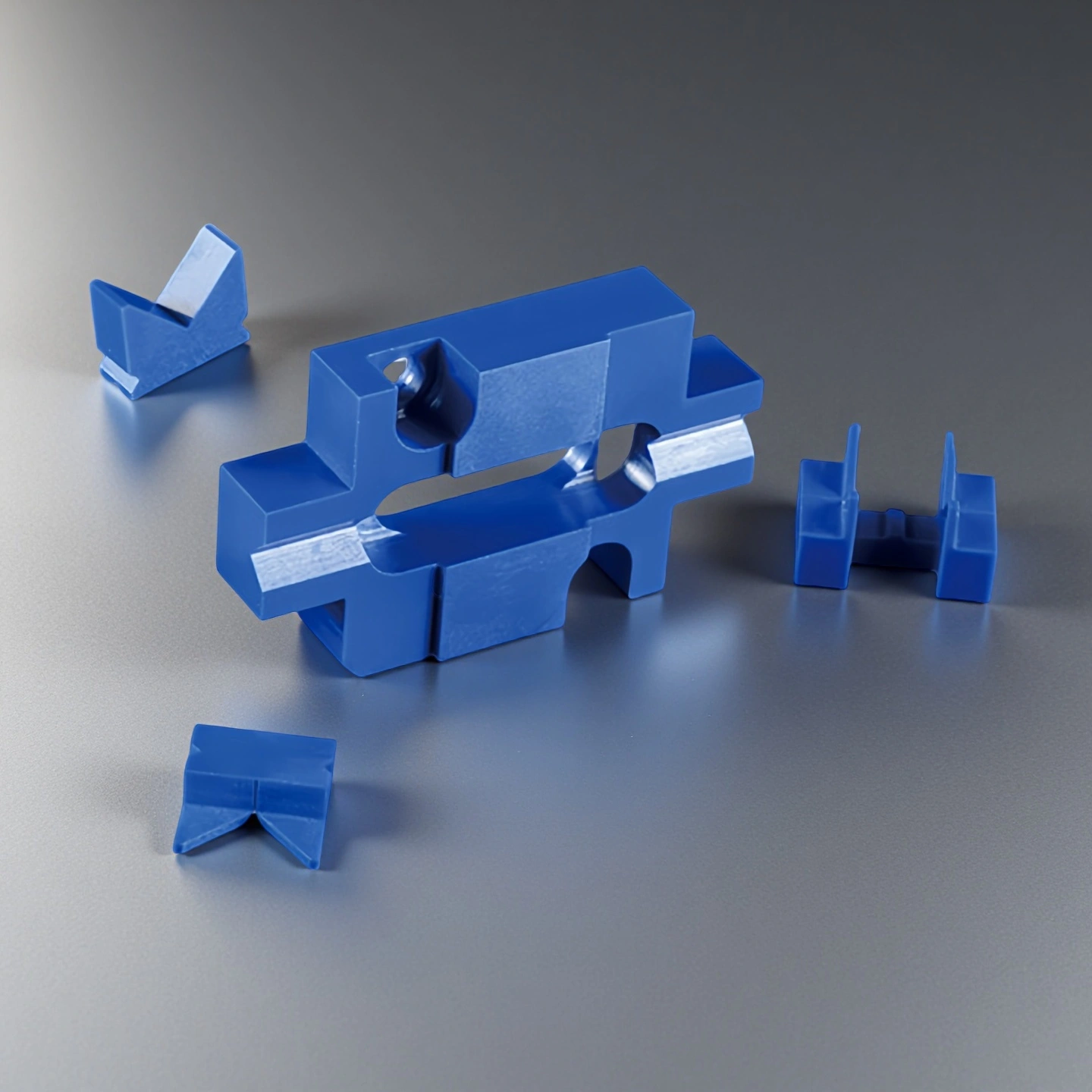
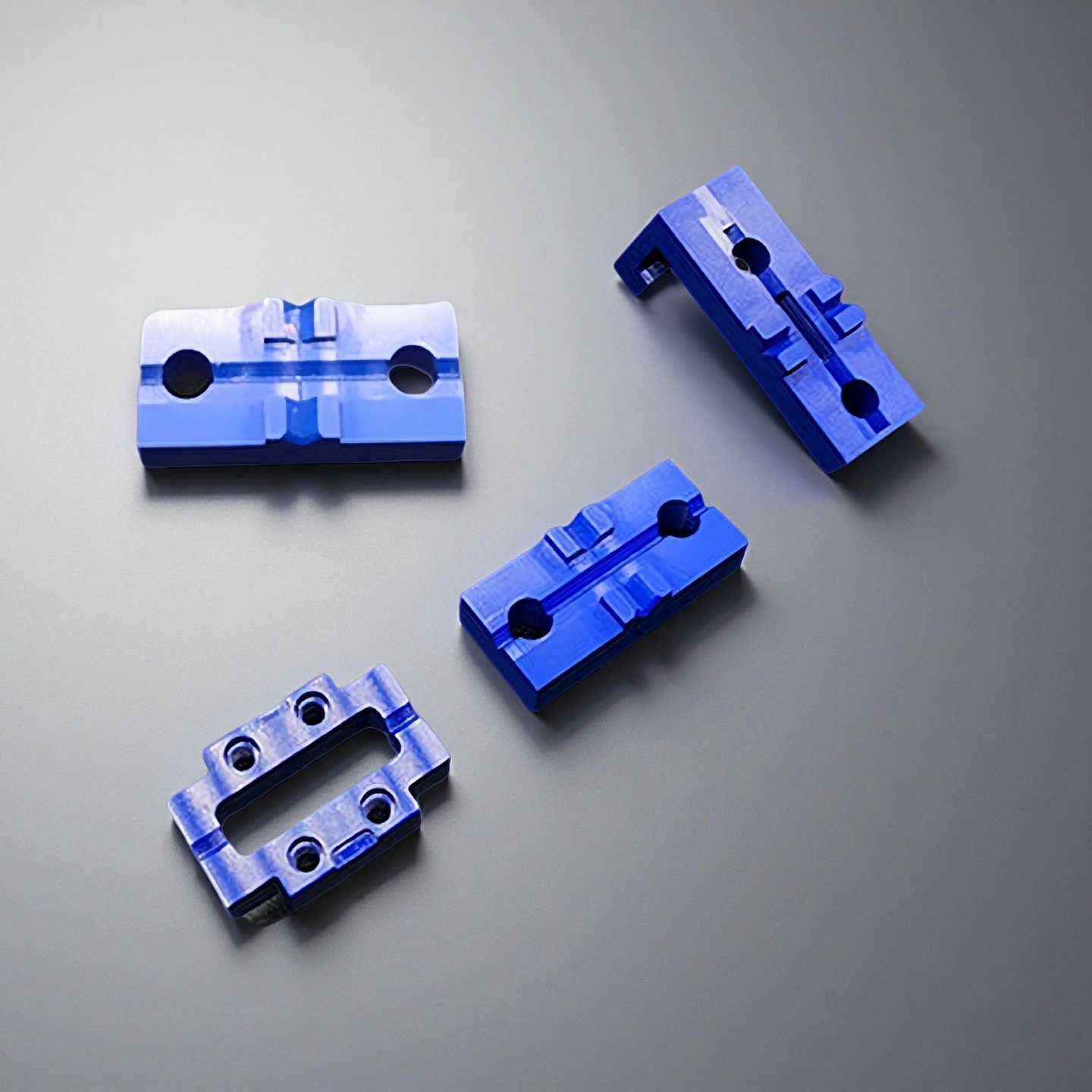
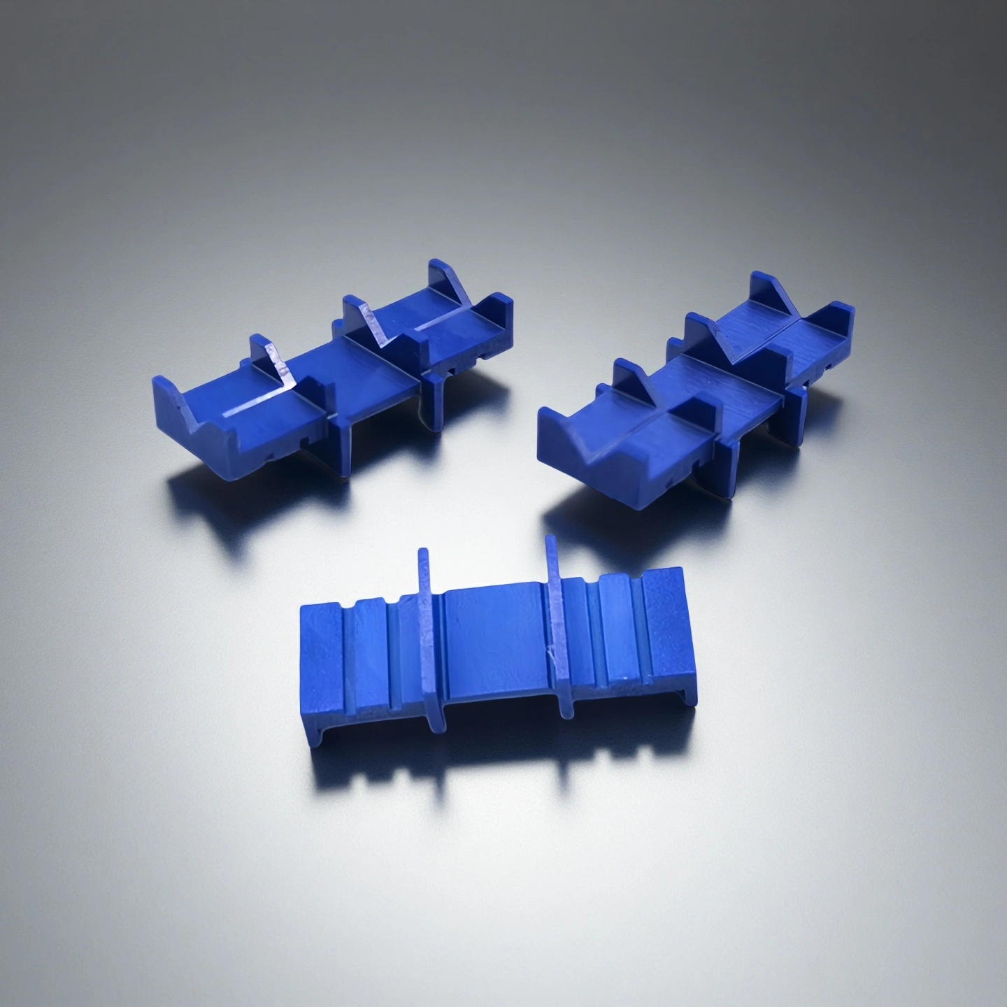
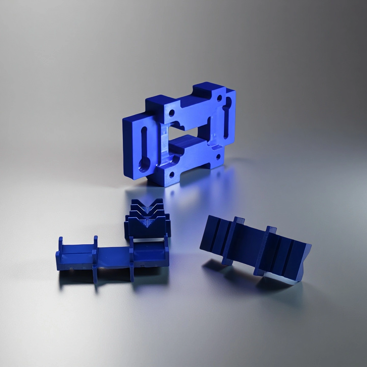
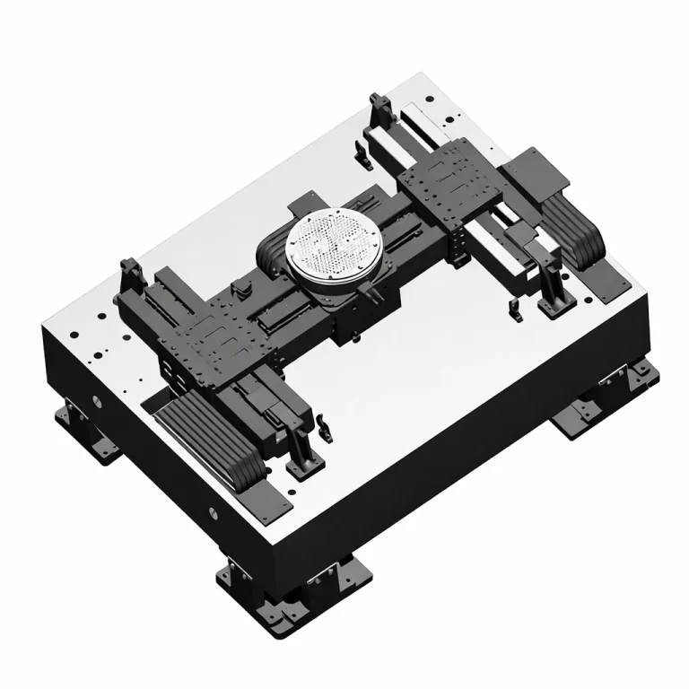
ADCERAX® Zirconia Ceramic V Groove is a precision-engineered component designed to secure and align optical fibers within fusion splicer systems. It ensures accurate fiber positioning by preventing lateral or axial displacement during the splicing process. This alignment stability contributes to low insertion loss and long-term performance in both field operations and laboratory applications.
Key Performance Features of Zirconia Ceramic V Groove
- High Hardness (HV > 1,200): This prevents micro-wear and deformation during fiber loading, preserving groove integrity over 200,000+ cycles. Even under point load, dimensional deviation remains below ±1 µm.
- High Elastic Modulus (~210 GPa): Enables the groove to maintain consistent fiber pressure without bending, ensuring stable contact during electric arc fusion. Material stiffness resists external vibration or thermal-induced stress.
- Zero Structural Creep at 1,000°C: Structural distortion is negligible at typical splicer temperatures. Long-term heat exposure tests show <0.02% deviation in groove depth after 100 thermal cycles.
- Groove Angle Tolerance ±0.02°: Minimizes angular deviation in fiber seating. Ensures insertion loss stays below 0.05 dB across most single-mode applications.
- Pitch Error ≤0.5 µm per 10 mm: Essential for ribbon fiber or PIC array configurations, avoiding optical path mismatch. This pitch uniformity surpasses industry norms by 20–30%.
- Surface Roughness ≤0.02 µm (Ra): Polished contact surfaces reduce light scattering and insertion variance. This contributes to consistent fusion performance in both single and multi-core fibers.
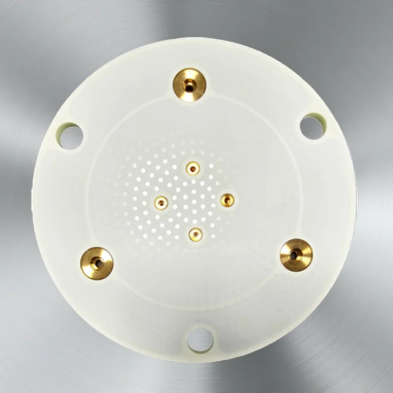
- Blue Zirconia Surface: Enhances visual confirmation of fiber position during setup. Field reports show a 32% reduction in fiber misplacement incidents when using blue grooves versus white or metallic.
- Anti-Reflective Coating Available: Optional SiO₂ finish reduces glare under microscope illumination, improving technician alignment visibility by 15–20%.
- Color-Coded Fiber Slots: Multichannel configurations support groove differentiation by hue, aiding technicians in minimizing handling errors. This reduces channel cross-insertion risk by over 40%.
Technical Properties of Zirconia Ceramic V Groove
The Zirconia Ceramic V Groove is engineered to ensure high structural integrity, thermal resilience, and optical alignment accuracy in demanding splicing and photonics environments. Its material composition and surface properties are optimized for repeatable high-cycle performance and precise optical control across a wide range of operating conditions.
| Property |
Specification |
| Material Purity |
≥99.8% Yttria-Stabilized Zirconia |
| Crystal Structure |
Tetragonal (3Y-TZP) |
| Density |
≥6.05 g/cm³ |
| Vickers Hardness |
>1,200 HV |
| Flexural Strength |
900–1,200 MPa |
| Fracture Toughness |
7–10 MPa·m¹ᐟ² |
| Elastic Modulus |
~210 GPa |
| Thermal Conductivity |
2.5 W/m·K (at 20 °C) |
| Coefficient of Thermal Expansion |
10.5 × 10⁻⁶ K⁻¹ (20–800 °C) |
| Electrical Resistivity |
>10¹² Ω·cm (at 20 °C) |
| Surface Roughness (Ra) |
≤0.02 µm |
| Groove Angle Tolerance |
±0.02° |
| Multi-Channel Pitch Accuracy |
≤0.5 µm / 10 mm |
| Color Coding (Visual Aid) |
Blue or White Surface Dopant |
| Operating Temperature Range |
–40 °C to 1,000 °C continuous |
Specifications of Zirconia Ceramic V Groove
|
Zirconia Ceramic V Groove |
|
Item NO. |
Diameter (mm) |
Width(mm) |
|
AT-YHG-ZJ1001 |
Customize |
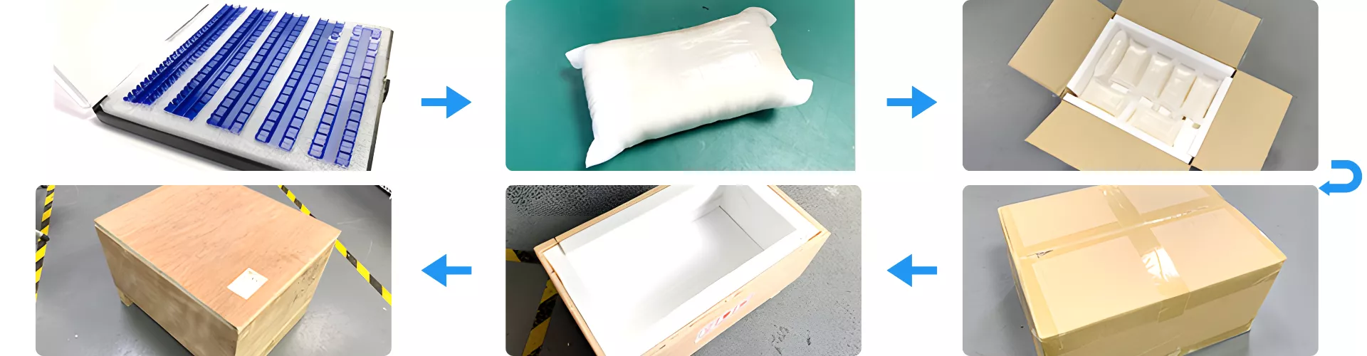
Packaging of Zirconia Ceramic V Groove
Zirconia Ceramic V Groove components are first placed in precision-aligned trays to prevent micro-movement during transit. Each tray is sealed in protective foam pouches, layered inside impact-resistant cartons with custom-cut inserts. Final packaging includes double-corrugated boxes and reinforced plywood crates to ensure safe global delivery.
Solving Alignment and Stability Challenges in Fiber Systems with ADCERAX® Zirconia Ceramic V Groove
ADCERAX® Zirconia Ceramic V Groove addresses critical mechanical and optical alignment issues across fiber-based communication and photonic systems. Its dimensional accuracy, thermal resilience, and wear resistance make it essential in applications where stable positioning and long-term reliability are non-negotiable.
-
High-Volume Field Fiber Splicing in FTTx Installations
✅Key Advantages
1. Enhanced Wear Resistance
The ADCERAX® Zirconia Ceramic V-Groove maintains structural integrity after more than 200,000 splicing cycles, resisting surface abrasion that typically degrades conventional grooves after 20,000 uses. Its Vickers hardness exceeding 1,200 HV ensures consistent fiber seating throughout large-scale deployments.
2. Stable Optical Performance in Dusty Environments
The low surface roughness of ≤0.02 µm Ra minimizes contamination buildup and misalignment caused by dust exposure. Field testing under simulated outdoor conditions demonstrated <0.05 dB insertion loss even after extended operation in high-dust zones.
3. Thermal Reliability for Field Variability
Designed to sustain operation from –40 °C to 1,000 °C, the material’s thermal expansion coefficient of 10.5 × 10⁻⁶ K⁻¹ prevents geometric drift under rapid temperature changes during daytime outdoor work.
✅ ️Problem Solved
Maintaining Fiber Alignment in Harsh Outdoor Deployments
During a metropolitan broadband rollout, a regional contractor reported groove wear and fiber slippage in conventional ceramic fixtures after just 8,000 splices. Replacing them with ADCERAX® Zirconia Ceramic V-Grooves reduced re‑splicing incidents by 78% and eliminated daily recalibration. Over a three‑month field test, insertion loss remained below 0.06 dB, cutting maintenance costs by nearly 40% compared with previous components.
-
Multi-Fiber Ribbon Splicing in Data Center Cabling
✅Key Advantages
1. Ultra‑Tight Pitch Control
With a verified pitch deviation of ≤0.5 µm per 10 mm, the ADCERAX® design guarantees channel‑to‑channel uniformity during 12‑fiber ribbon alignment. It enables consistent optical transmission without calibration drift in high‑density connectors.
2. Low‑Loss Multi‑Fiber Splicing
Precision groove angle of ±0.02° maintains identical contact geometry across fibers, ensuring typical insertion loss stays under 0.05 dB even after multiple thermal cycles. This stability supports the stringent optical budgets of hyperscale data centers.
3. Fatigue‑Free Surface Symmetry
Mechanical cycle testing showed no measurable deformation after 150,000 splicing repetitions, demonstrating long‑term reliability under continuous production conditions and minimizing downtime for tool replacement.
✅ ️Problem Solved
Eliminating Pitch Drift in High‑Density Data Infrastructure
A Tier‑1 data center integrator experienced optical mismatch in 12‑core ribbons due to groove deformation in glass fixtures, resulting in 0.2 dB signal variance per channel. Switching to ADCERAX® Zirconia Ceramic V‑Groove improved pitch consistency by 30% and reduced cumulative loss to below 0.05 dB across all fibers. The upgraded alignment modules operated for nine months without requiring a single recalibration, achieving continuous 24/7 service stability.
-
Passive Alignment in PIC/PLC Photonic Module Assembly
✅Key Advantages
1. Sub‑Micron Geometric Uniformity
Machined groove surfaces achieve flatness ≤2 µm and angular precision within ±0.02°, supporting passive fiber‑to‑chip alignment where coupling loss tolerance is below 0.1 dB. This enables consistent optical interface integration in PLC and PIC modules.
2. High Fracture Toughness and Dimensional Stability
With a fracture toughness of 7–10 MPa·m¹/², the ADCERAX® V‑Groove withstands micro‑stress from packaging clamps without chipping or shape drift, ensuring exact positioning through the entire bonding process.
3. Dielectric and Thermal Insulation
Electrical resistivity exceeding 10¹² Ω·cm isolates the groove from electrostatic interference during laser or electrode bonding, while low thermal conductivity of 2.5 W/m·K prevents localized heat distortion near optical interfaces.
✅ ️Problem Solved
Achieving Stable Passive Alignment in Photonic Packaging
A European photonics firm reported coupling loss variations exceeding 0.12 dB in 1×8 PLC splitters using polymer‑based alignment tools. After adopting ADCERAX® Zirconia Ceramic V‑Grooves, angular deviation dropped below 0.02°, and coupling loss stabilized at <0.06 dB across all channels. The improved precision shortened assembly time by 22%, enabling consistent sub‑micron passive alignment without requiring active feedback calibration.
Practical Handling and Maintenance Guide for Zirconia Ceramic V Groove
To ensure optimal performance, stability, and lifecycle value of the Zirconia Ceramic V Groove, users must follow correct usage, cleaning, inspection, and storage practices. This section provides essential guidance for engineers and technicians working across fiber splicing, photonic packaging, and module assembly environments.
-
Daily Operation Recommendations
1. Position fibers gently using precision tweezers to avoid chipping the groove edges. Excessive pressure or dragging motion can cause microscopic wear, affecting long-term positioning accuracy. Always align fiber cores along the designed channel angle.
2. Inspect the groove for dust or debris before each use. Particulate buildup can lead to unstable seating or inaccurate alignment. A brief check under magnification prevents avoidable optical loss.
3. Avoid touching the groove with bare hands to reduce contamination from skin oils or moisture. This may interfere with fiber seating and accelerate surface degradation. Always use gloves or handling tools.
-
Cleaning and Maintenance Protocols
1. Use lint-free swabs with isopropyl alcohol (≥99.5%) to clean the groove contact surface. Aggressive solvents or coarse cloths will damage the polished channel finish. Clean every 50–100 splices depending on the environment.
2. Avoid ultrasonic cleaning unless approved for your groove configuration. Vibration may cause micro-fractures in high-frequency applications. Manual swab cleaning is typically sufficient.
3. Regularly check the groove surface for scratches, chips, or discoloration using a 100×–200× inspection scope. Replace the component immediately if groove integrity is compromised.
-
Handling and Assembly Precautions
1. Do not apply uneven force during groove mounting into fusion splicer trays or custom holders. Misalignment during installation may result in pitch deviation or mechanical stress.
2. Tighten mounting screws to the specified torque if applicable. Over-tightening can crack the zirconia base, especially in multi-channel configurations. Undue loosening may introduce vibration.
3. Verify alignment compatibility with mating components such as fiber holders or clamps before system integration. Poor tolerance matching may lead to axial shift during splicing.
-
Storage and Replacement Guidelines
1. Store grooves in anti-static, padded enclosures to prevent mechanical damage and electrostatic discharge. Humid environments accelerate material degradation if improperly packed.
2. Maintain an operating temperature between –40 °C and 1000 °C, and avoid thermal shock. Rapid transitions between extremes may affect structural performance.
3. Track splice cycle counts or operational hours per unit to estimate lifecycle. Most grooves should be replaced after 200,000+ cycles, or earlier if performance degradation is observed.