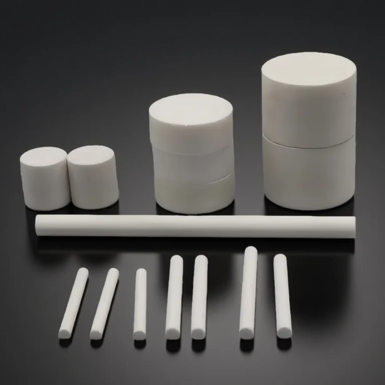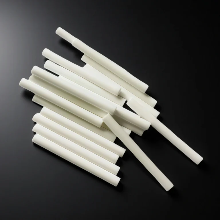

Alumina ceramic support shaft is a load-bearing shaft made from high-purity alumina used to support, align and space components inside industrial equipment such as kilns, furnaces, process pumps, mixers and fixtures. It combines a rigid ceramic body with ground functional seats, controlled geometry and optional stepped or locating ends, so that critical contact points keep stable fit, alignment and wear performance where metal shafts may deform, corrode or fail at elevated temperature.
Alumina Ceramic Support Shaft Advantages
-
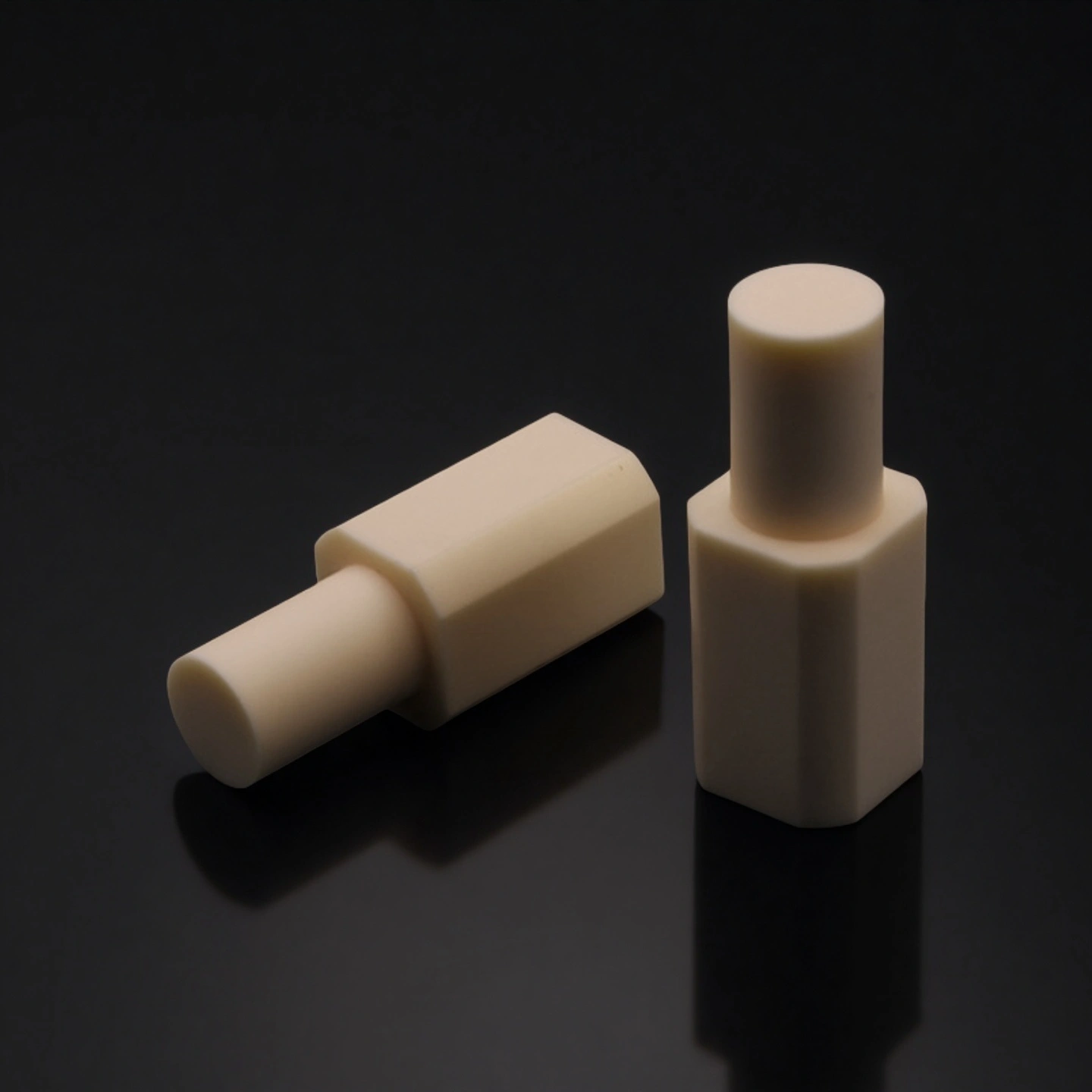
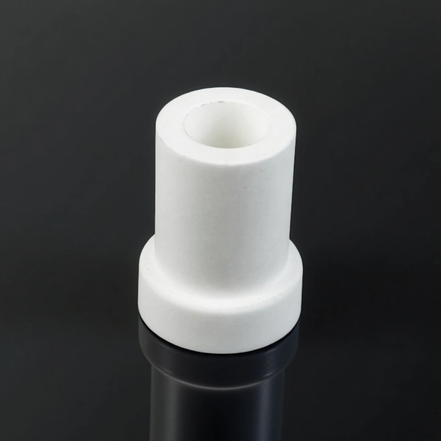
Functional-zone grinding keeps tight tolerances and controlled surface finish only on bearing seats and mating diameters, improving press-fit or slip-fit behavior and reducing assembly rework on neighbouring parts.
-
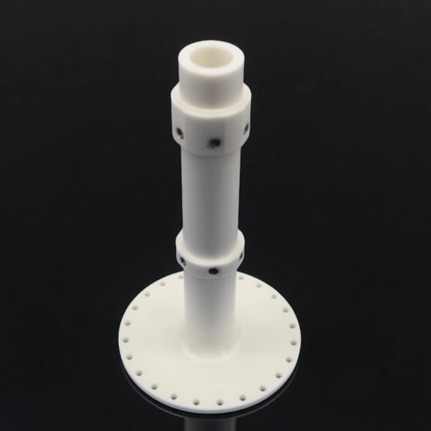
Stepped ends/locating features provide defined shoulders, chamfers, or reference faces so the alumina ceramic support shaft drops into fixtures, carriers, and support frames with repeatable axial and radial positioning.
-
Controlled geometry on critical sections allows you to call out concentricity, straightness, and runout on specific zones, helping to limit misalignment-related wear at guides, bushings, or support points.
-
Segmented finishing options let you combine ground or polished functional zones with as-fired non-critical areas, balancing performance and cost while still protecting fit-critical regions from damage.
-
Repeat-order consistency focus keeps the same critical diameters, seat lengths, and finishes stable from sample to batch production, which supports MRO spare programs and long-term replacement cycles.
-
Straightness and deflection control targets long shafts that span multiple supports, limiting sag or bow so contact loads stay more evenly distributed along rollers, fixtures, or support rails.
-
Installation-friendly edge details such as controlled edge breaks and lead-in chamfers on shaft ends help prevent chipping during handling and make insertion into bushings or guides smoother and more predictable.
Alumina Ceramic Support Shaft Properties
| Property | Unit | 96% Al₂O₃ | 99% Al₂O₃ | 99.5% Al₂O₃ | 99.6% Al₂O₃ | 99.7% Al₂O₃ | 99.8% Al₂O₃ | 99.9% Al₂O₃ | 99.99% Al₂O₃ |
| Alumina content | % | 96 | 99 | 99.5 | 99.6 | 99.7 | 99.8 | 99.9 | 99.99 |
| Density | g/cm³ | 3.6-3.75 | 3.83 | 3.89 | 3.91 | 3.92 | 3.93 | 3.94 | 3.98 |
| Color | – | white | Ivory | Ivory | Ivory | Ivory | Ivory | Ivory | Ivory |
| Water absorption | % | 0 | 0 | – | 0 | 0 | 0 | 0 | 0 |
| Young’s modulus (Elastic modulus) | GPa | 300 | 350 | 375 | 356 | 357 | 358 | 359 | 362 |
| Shear modulus | GPa | – | – | 152 | – | – | – | – | – |
| Bulk modulus | GPa | – | – | 228 | – | – | – | – | – |
| Poisson’s ratio | – | – | – | 0.22 | – | – | – | – | – |
| Compressive strength | MPa | 1910 | 2210 | 2600 | 2552 | 2554 | 2556 | 2558 | 2570 |
| Flexural strength | MPa | 260 | 300 | 379 | 312 | 313 | 314 | 315 | 320 |
| Fracture toughness | MPa·m¹ᐟ² | – | – | 4 | – | – | – | – | – |
| Hardness | GPa | 14.5 | 17 | 17 | 23 | 24 | 25 | 26 | 30 |
| Thermal conductivity | W/m·K | 22 | 24 | 35 | 32–37 | 33–38 | 34–39 | 35–40 | 36–42 |
| Thermal shock resistance ΔT | °C | – | – | – | 222 | 223 | 224 | 225 | 228 |
| Maximum use temperature (no load) | °C | 1450 | 1680 | ≤1750 | 1755 | 1760 | 1765 | 1770 | 1800 |
| Coefficient of thermal expansion | 10⁻⁶/°C | 7.6 | 7.6 | 8.4 | – | – | – | – | – |
| Volume resistivity | Ω·cm | >1×10¹⁴ | >1×10¹⁴ | >1×10¹⁴ | >1×10¹⁴ | >1×10¹⁴ | >1×10¹⁴ | >1×10¹⁴ | >1×10¹⁴ |
| Dielectric constant (relative permittivity) | – | 9.2 | 9.5 | 9.8 | 9.83 | 9.84 | 9.85 | 9.86 | 9.92 |
| Dielectric strength | kV/mm | 15 | 19 | 16.9 | 23.2 | 23.4 | 23.6 | 23.8 | 24 |
| Dissipation factor (loss factor @ 1 kHz) | – | – | – | 0.0002 | – | – | – | – | – |
Al2O3 Ceramic Support Shaft Specifications
Type 1: Al2O3 Ceramic Support Shaft
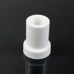
| Type 1: Al2O3 Ceramic Support Shaft | ||||||||
| Item No. | Top diameter(mm) | Top inner diameter(mm) | Bottom diameter(mm) | Bottom inner diameter(mm) | Ring width(mm) | Ring thickness(mm) | Height(mm) | Purity |
| AT-AX-001 | 24 | 14 | 18 | 14 | 8 | 3 | 35 | 96%-99% |
| AT-AX-002 | 26 | 16 | 20 | 16 | 10 | 3 | 45 | 96%-99% |
| AT-AX-003 | 28 | 18 | 22 | 18 | 11 | 3 | 50 | 96%-99% |
| AT-AX-004 | 30 | 18 | 24 | 18 | 13 | 3 | 75 | 96%-99% |
| AT-AX-005 | 50 | 40 | 45 | 35 | 9 | 2.5 | 100 | 96%-99% |
| AT-AX-006 | 60 | 50 | 53 | 43 | 12 | 3.5 | 200 | 96%-99% |
| AT-AX-007 | 70 | 60 | 61 | 51 | 15 | 4.5 | 300 | 96%-99% |
| AT-AX-008 | 80 | 70 | 73 | 63 | 30 | 3.5 | 400 | 96%-99% |
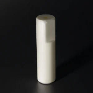
Type 2: Al2O3 Ceramic Support Shaft

| Type 2:Al2O3 Ceramic Support Shaft | |||||
| Item No. | Top Length(mm) | Top Width(mm) | Bottom diameter(mm) | Height(mm) | Purity |
| AT-AX-009 | 8 | 8 | 4 | 20 | 96%-99% |
| AT-AX-010 | 10 | 10 | 6 | 40 | 96%-99% |
| AT-AX-011 | 16 | 16 | 12 | 35 | 96%-99% |
| AT-AX-012 | 20 | 20 | 14 | 70 | 96%-99% |
| AT-AX-013 | 22 | 22 | 15 | 80 | 96%-99% |
| AT-AX-014 | 24 | 24 | 18 | 50 | 96%-99% |
| AT-AX-015 | 28 | 28 | 20 | 65 | 96%-99% |
| AT-AX-016 | 30 | 30 | 15 | 70 | 96%-99% |
| AT-AX-017 | 35 | 35 | 22 | 90 | 96%-99% |
| AT-AX-018 | 38 | 38 | 28 | 100 | 96%-99% |
| AT-AX-019 | 40 | 40 | 30 | 120 | 96%-99% |
| AT-AX-020 | 50 | 50 | 35 | 160 | 96%-99% |
Type 3: Al2O3 Ceramic Support Shaft
| Type 3:Al2O3 Ceramic Support Shaft | ||||
| Item No. | Outer diameter(mm) | Inner diameter(mm) | Length(mm) | Purity |
| AT-AX-021 | 5 | 3 | 10 | 96%-99% |
| AT-AX-022 | 7 | 3 | 120 | 96%-99% |
| AT-AX-023 | 10 | 6 | 50 | 96%-99% |
| AT-AX-024 | 16 | 11 | 70 | 96%-99% |
| AT-AX-025 | 20 | 14 | 200 | 96%-99% |
| AT-AX-026 | 35 | 30 | 80 | 96%-99% |
| AT-AX-027 | 40 | 30 | 120 | 96%-99% |
| AT-AX-028 | 58 | 48 | 130 | 96%-99% |
| AT-AX-029 | 60 | 50 | 150 | 96%-99% |
| AT-AX-030 | 80 | 70 | 200 | 96%-99% |
![]() Download Alumina Ceramic Support Shaft
Download Alumina Ceramic Support Shaft
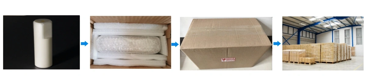
Alumina Ceramic Support Shaft Packaging
- Individual shaft separation using foam sleeves or partitions to prevent contact chipping.
- Shock protection with multi-layer cushioning at ends (highest break-risk points).