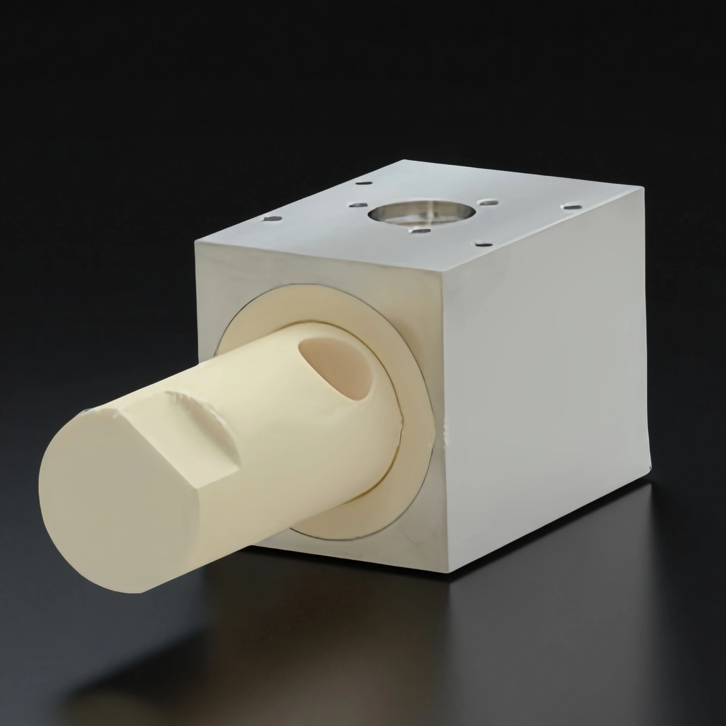
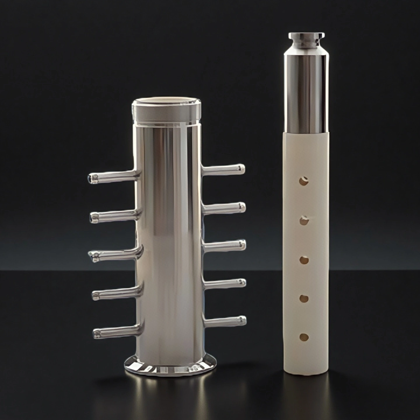
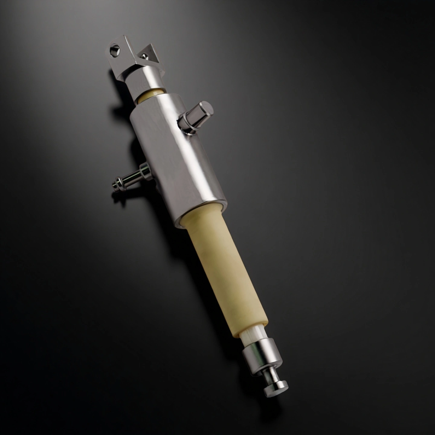
What Is an Alumina Ceramic Filling Pump?
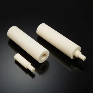
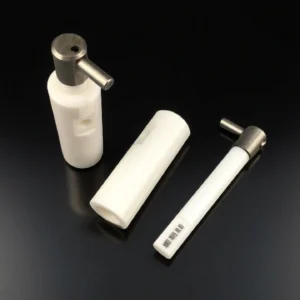
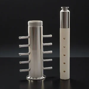
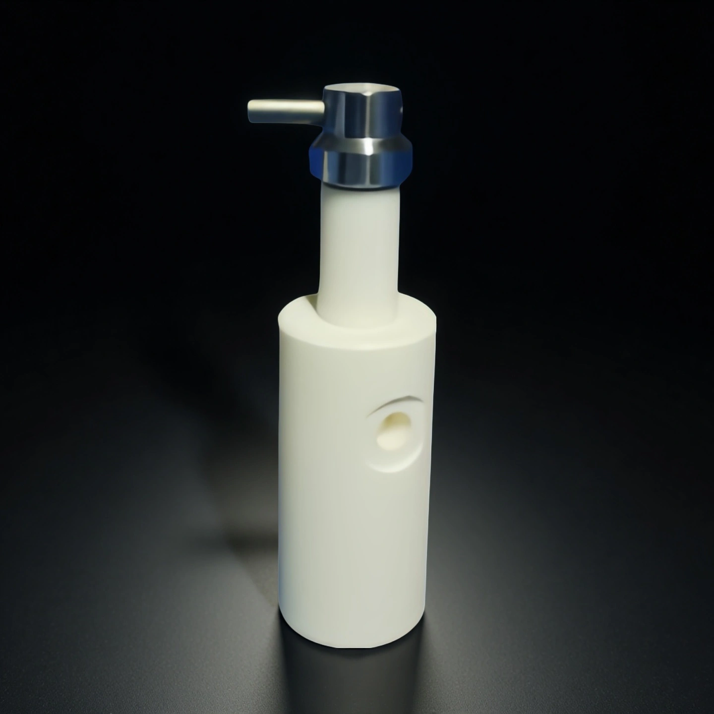
An alumina ceramic filling pump is a ceramic metering pump component used in filling machines to control the movement of liquids, creams, gels, pastes and other process media. The main wear surfaces are usually the ceramic plunger, pump barrel, rotary valve or valve seat. Compared with stainless steel or coated metal parts, alumina ceramic offers high hardness, chemical stability and a polished contact surface that helps reduce wear, scoring and dose drift in suitable media conditions.
Reference Volume Options for Alumina Ceramic Filling Pump Heads
The following volume ranges are reference options for early engineering selection. Final filling accuracy, ceramic grade, pump geometry and lead time should be reviewed according to media viscosity, stroke design, valve structure, equipment interface, seal material and cleaning method.
Type 1: Alumina Filling Pump For Cosmetics
| Alumina Filling Pump For Cosmetics | |||
| Model No. | Volume (mL) | Al₂O₃ Purity | Reference Filling Accuracy |
| AT-CP-001 | 0.2 | 95-99 | <1% |
| AT-CP-002 | 0.5 | 95-99 | <1% |
| AT-CP-003 | 1 | 95-99 | <1% |
| AT-CP-004 | 2 | 95-99 | <1% |
| AT-CP-005 | 3 | 95-99 | <0.5% |
| AT-CP-006 | 5 | 95-99 | <0.5% |
| AT-CP-007 | 7 | 95-99 | <0.5% |
| AT-CP-008 | 10 | 95-99 | <0.5% |
| AT-CP-009 | 15 | 95-99 | <0.5% |
| AT-CP-010 | 16 | 95-99 | <0.5% |
| AT-CP-011 | 20 | 95-99 | <0.5% |
Type 2: Alumina Filling Pump for Laboratory Reagents and Hygienic Filling Systems
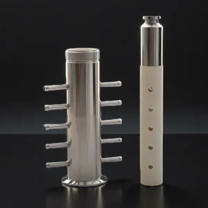
| Alumina Filling Pump For Pharmaceutical and Biological Agents | |||
| Item NO. | Volume (mL) | Al₂O₃ Purity (%) | Reference Filling Accuracy |
| AT-CP-1001 | 0.5 | 95-99 | <1% |
| AT-CP-1002 | 1 | 95-99 | <1% |
| AT-CP-1003 | 2 | 95-99 | <1% |
| AT-CP-1004 | 3 | 95-99 | <0.5% |
| AT-CP-1005 | 5 | 95-99 | <0.5% |
| AT-CP-1006 | 7 | 95-99 | <0.5% |
| AT-CP-1007 | 10 | 95-99 | <0.5% |
| AT-CP-1008 | 15 | 95-99 | <0.5% |
| AT-CP-1009 | 16 | 95-99 | <0.5% |
| AT-CP-1010 | 20 | 95-99 | <0.5% |
| AT-CP-1011 | 30 | 95-99 | <0.5% |
| AT-CP-1012 | 40 | 95-99 | <0.5% |
Type 3: Alumina Filling Pump For Food
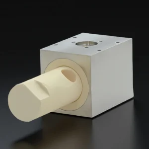
| Alumina Filling Pump For Food | |||
| Item NO. | Volume (mL) | Al₂O₃ Purity (%) | Reference Filling Accuracy |
| AT-CP-2001 | 1 | 95-99 | <1% |
| AT-CP-2002 | 2 | 95-99 | <1% |
| AT-CP-2003 | 3 | 95-99 | <0.5% |
| AT-CP-2004 | 5 | 95-99 | <0.5% |
| AT-CP-2005 | 7 | 95-99 | <0.5% |
| AT-CP-2006 | 10 | 95-99 | <0.5% |
| AT-CP-2007 | 15 | 95-99 | <0.5% |
| AT-CP-2008 | 16 | 95-99 | <0.5% |
| AT-CP-2009 | 20 | 95-99 | <0.5% |
| AT-CP-2010 | 30 | 95-99 | <0.5% |
| AT-CP-2011 | 40 | 95-99 | <0.5% |
| AT-CP-2012 | 40-220 | 95-99 | <0.5% |
Type 4: Alumina Filling Pump For Battery Electrolytes
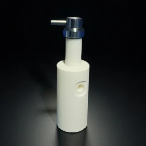
| Alumina Filling Pump For Battery Electrolytes | ||||
| Item NO. | Volmue (ml) | Purity (%) | Volume ofBattery Electrolytes (g) | Filling Accuracy (%) |
| AT-CP-3001 | 0.5 | 95-99 | 0.5g | <0.3% |
| AT-CP-3002 | 1 | 95-99 | 1g | <0.3% |
| AT-CP-3003 | 2 | 95-99 | 3g | <0.3% |
| AT-CP-3004 | 3 | 95-99 | 8g | <0.3% |
| AT-CP-3005 | 4 | 95-99 | 18g | <0.3% |
| AT-CP-3006 | 5 | 95-99 | 40g | <0.3% |
Alumina Grade Reference for Pump Components
These values are reference properties for alumina ceramic pump components. Final material grade, tolerance, surface finish and media compatibility should be reviewed according to pump geometry, filling volume, media viscosity, cleaning method, seal material and equipment interface.
| Property | AD-ALU-950 | AD-ALU-960 | AD-ALU-990 | AD-ALU-995 | AD-ALU-997 | AD-ALU-999 |
|---|---|---|---|---|---|---|
| Nominal Al₂O₃ (wt%) | 95 | 96 | 99.00 | 99.50 | 99.70 | 99.90 |
| IEC 60672-3 composition group | C795 | C795 | C795 | C799 | C799 | C799 |
| Density (g/cm³, typical) | 3.75 | 3.70 | 3.80–3.91 | 3.90–3.92 | 3.94 | 3.94 |
| Flexural strength (MPa, 20 °C, typical) | 280 | 300 | 300–320 | 320–350 | 330 | 315–340 |
| Compressive strength (MPa, 20 °C, typical) | 2000 | 2000 | 2400 | 2400 | 2500 | 2558–2900 |
| Young's modulus (GPa, typical) | 340 | 275 at 20 °C | 355 | 365 | 370 | 359–375 |
| Fracture toughness KIC (MPa·m½, method-dependent) | 3.0 | 3.5 at 20 °C | 3.3 | 3.5 | 3.6 | 3.8–4.2 |
| Thermal conductivity (W/(m·K), typical) | 18–25 at 25 °C | 25 at 20 °C | 24 at 25 °C | 30–38 at 25 °C | 35–40 at 25 °C | 35–42 at 25 °C |
| Mean CTE (10⁻⁶/K) | 7.6, 25–800 °C | 8.2, 25–1000 °C | 7.2, 25–800 °C | 7.6, 25–800 °C | 7.6, 25–800 °C | 7.6, 25–800 °C |
| Water absorption (%, selection limit) | ≤0.20 | ≈0 | ≤0.10 | ≤0.10 | ≤0.05 | ≤0.01 |
| Mohs hardness (typical) | 9 | — | 9 | 9 | 9 | 9 |
| Use temperature guide (°C, application-dependent) | 1400 | 1600 max in air | 1600 | 1650 | 1700 | 1750 |
Choose the Supply Unit for Your Filling Equipment
A filling pump project can start at three supply levels. Each has a different document set, so naming the level first keeps the drawing review short.
| Supply unit | Product scope | Selection basis |
|---|---|---|
| Ceramic wear part | Plunger, barrel, valve seat or outlet component | Drawing, working surface and mating part |
| Matched wear set | Specified plunger–barrel and valve components | Matched clearance, valve layout and set BOM |
| Drawing-based pump head | Specified ceramic parts, housing and connections | Interface drawing and agreed supply list |
For a replacement project, an equipment nameplate, old-part number and photographs help identify the assembly. The drawing or sample then establishes its working geometry and interfaces.
What to Specify in a Filling Pump Wear Set
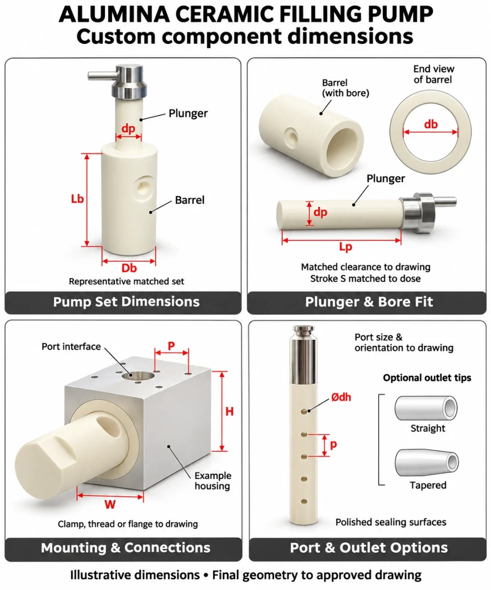
Hard working surfaces. Define the ceramic grade, plunger diameter, barrel bore and surface finish together for the mating wear parts.
Matched geometry. Keep clearance, bore roundness, valve port phase and assembly alignment on one drawing revision.
Cleanable wet end. Specify purge ports, drain angles, seal positions and cleaning conditions for flushing, drying and formula changeover.
Ceramic contact surfaces. Identify ceramic and metal surfaces throughout the flow path. Include seals, fittings and housing interfaces in the compatibility review.
Common Filling Pump Failure Modes and What to Check
1. Gradual Underfill
Symptom: The dose slowly drops below target without an alarm.
- Check: Air in the chamber, interface seal leakage and plunger–barrel wear.
- Next step: Re-prime and repeat calibration using the same fluid and speed. If underfill returns, inspect the wear pair and seals.
2. Rising Torque or a Stiff Stroke
Symptom: The stroke feels heavy or the drive current increases.
- Check: Valve-seat alignment and particles trapped on the seating face.
- Next step: Flush according to the equipment procedure and re-seat the valve. Inspect for seat damage and check the plunger separately for scoring or leakage.
3. Dripping After the Stroke Stops
Symptom: Fluid continues to drip after filling ends.
- Check: Outlet tip wear, line pressure decay, anti-drip settings and valve-seat condition.
- Next step: Record the drip pattern before adjusting settings or replacing the tip.
Keep an inspection record: Note the formula, dose setting and operating conditions. ADCERAX reviews these records with the drawing revision to identify the required replacement part, matched set or seal.
Key Features for a Filling Pump Wear Set
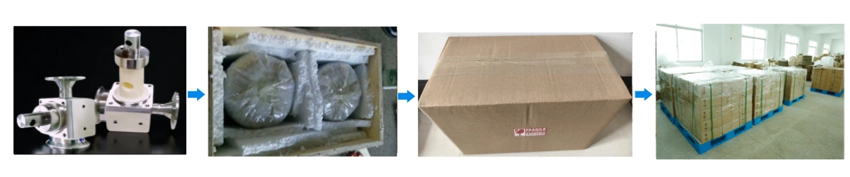
Alumina Ceramic Filling Pump Packaging
- Each plunger/barrel/valve seat set is separated with soft liners and bagged to keep surfaces clean.