SiC Lined Internal Gear Pump for Abrasive, Viscous and Corrosive Fluids

ADCERAX supplies silicon carbide lined internal gear pumps for abrasive, viscous and chemically aggressive fluid transfer in hydraulic, lubrication and process-fluid systems.

The SiC contact parts can include chamber liners, wear plates, bushings and mechanical seal faces, depending on the pump design and working media. Before quotation, our team reviews flow rate, pressure, viscosity, temperature, particle content, sealing method, port size and installation layout to confirm whether a SiC lined internal gear pump is suitable for your operating conditions.

Catalogue No. AT-IGP-18.3
Material Silicon Carbide–Lined Chamber, SiC Wear Plates, SiC Bushings, SiC Mechanical Seal Faces
Thermal Stability Low CTE (4.0–4.5 × 10⁻⁶ /K) maintains internal geometry from 20–80°C service temperature
Abrasion Resistance SiC hardness above 2000 HV supports long wear life in particulate-rich lubrication and hydraulic systems
Chemical Compatibility Inert to acids, bases, glycols, polymers; corrosion rate reduction > 0.3 mm/year vs alloy steel
Engineering RFQ Review
Small-Batch Custom Support
Factory-Direct Manufacturing
Drawing & Process Review

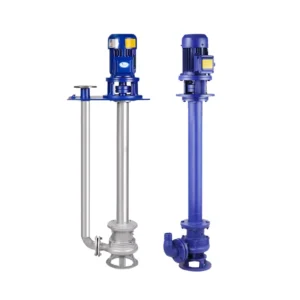
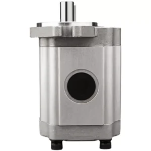
What Is a Silicon Carbide Lined Internal Gear Pump?

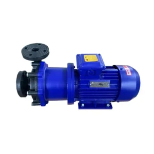
A silicon carbide lined internal gear pump is a positive displacement pump designed for controlled transfer of abrasive, viscous or chemically aggressive fluids. The internal gear mechanism provides steady flow, while silicon carbide contact parts help reduce wear on surfaces exposed to particles, corrosion or temperature-related dimensional changes.

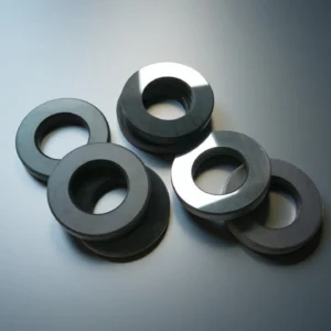
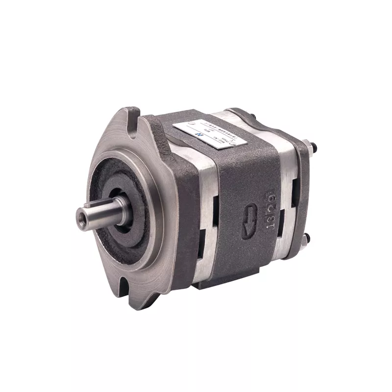
In a custom pump configuration, the SiC contact areas may include chamber liners, wear plates, bushings and mechanical seal faces. ADCERAX reviews the fluid type, viscosity, pressure, temperature, solids content, sealing requirement and installation layout before recommending a suitable pump configuration.

When to Use a SiC Lined Internal Gear Pump?

This pump is suitable when conventional metal-contact gear pumps experience fast wear, leakage risk or unstable flow caused by contaminated oils, viscous fluids or chemically reactive media. It is commonly considered for hydraulic power units, lubrication circulation systems, resin transfer, polymer handling, heavy oil transfer and process-fluid circulation.

A SiC lined internal gear pump is not selected by material alone. The final configuration should be reviewed together with flow rate, pressure, viscosity, temperature, particle size, particle concentration, sealing method, drive speed and piping layout.

Performance Characteristics of Silicon Carbide Lined Internal Gear Pump

  • Thermal Expansion Control
    SiC components exhibit a thermal expansion coefficient of 4.0–4.5 × 10⁻⁶ /K, significantly lower than common pump metals. This stabilizes rotor engagement when fluid temperatures vary between 20–80°C, preventing growth in volumetric slip.
  • Structural Rigidity
    Silicon carbide provides a flexural strength in the range of 350–450 MPa, which protects the pump chamber from deformation under cycling loads. This rigidity maintains consistent flow delivery in environments where differential pressure fluctuates.
  • Reduced Material Loss
    SiC exhibits an erosion rate up to 10× lower than alloy steel when exposed to abrasive flow environments. This reduces internal wear progression, preserving efficiency in applications where circulating oils are contaminated by gear or bearing wear particles.
  • Broad Chemical Resistance
    Silicon carbide maintains integrity in acids, bases, glycols, and polymeric fluids documented to cause corrosion rates above 0.3 mm/year in standard metal housings. This allows stable operation in chemical-transfer applications using reactive or polymerizing media.
  • Low Reactivity with High-Viscosity Media
    SiC surfaces demonstrate negligible interaction with fluid viscosities up to 50,000 cSt, protecting the pump from thermal or chemical softening. This supports consistent volumetric output when transferring thick resins or adhesive compounds.
  • Seal Surface Performance
    SiC-to-SiC mechanical seal faces record leakage reductions of 30–40% compared to carbon-steel pairings under corrosive fluid exposure. This reduces operational interruptions in chemical circulation modules where seal integrity is a primary reliability factor.

Technical Specifications of Silicon Carbide Lined Internal Gear Pump

The following parameters help review whether a SiC-lined internal gear pump is suitable for abrasive, viscous or chemically aggressive fluid transfer. Final selection should be confirmed according to the actual fluid type, viscosity, temperature, pressure, particle condition, sealing method and installation layout.

Parameter Specification Why It Matters
SiC Contact Parts SiC lining, SiC wear plates, SiC bushings and SiC seal faces. This helps buyers understand which wetted or wear-exposed areas are protected by silicon carbide.
Surface Hardness > 2000 HV. High hardness helps reduce abrasive wear when the pump handles contaminated oils, metal fines or particle-containing fluids.
Chemical Compatibility Stable against acids, bases, glycols and polymers. Chemical compatibility helps buyers judge whether the pump is suitable for corrosive or chemically active media.
Recommended Service Temperature 20–80°C recommended. Media temperature affects viscosity, sealing behavior, internal clearance and pump stability.
Viscosity Handling Capability Suitable for up to 50,000 cSt. Viscosity is one of the most important factors for pump selection because it affects suction condition, motor load and flow stability.
Seal Face Configuration SiC/SiC or Carbon/SiC. Seal pairing affects leakage control, friction behavior and compatibility with abrasive or chemically aggressive fluids.
Abrasive Particle Tolerance Effective with 50–150 ppm metal fines. This helps buyers evaluate whether the pump is suitable for hydraulic oil, lubricating oil or process fluids with solid contamination.
Volumetric Efficiency Stability Maintained under cyclic pressure and viscosity fluctuations. Stable volumetric efficiency supports more predictable flow when pressure or viscosity changes during operation.
Flow Rate Requirement Confirm according to required L/min or m³/h. Flow rate is the first selection point for matching the pump model to the actual system demand.
Working Pressure Requirement Confirm according to normal and peak system pressure. Pressure affects pump housing selection, gear load, seal configuration and long-term operating stability.
Port and Installation Layout Confirm inlet/outlet size, direction and mounting interface. Port layout and installation dimensions determine whether the pump can fit into the existing piping and equipment system.

Standard Model Range for SiC Lined Internal Gear Pumps


Drawing of Silicon Carbide Lined Internal Gear Pump

Type 6 : Silicon Carbide Internal Gear Pump
Type Flow (m3/h) Flow (L/min) Working Pressure (MPA) Suction Vacuum Height (m) Import and export caliber (mm) Speed (Nr/min) Motor Power (KW)
AT-IGP-18.3 1.1 18.3 1.45 5 G3/4" 1400 1.5
AT-IGP-33.3 2 33.3 1.45 5 G3/4" 1420 2.2
AT-IGP-55 3.3 55 0.33 5 G1" 1400 1.5
AT-IGP-83.3 5 83.3 0.33 5 G1/2" 1420 2.2
AT-IGP-135 8 135 0.33 3 50 1440 4
AT-IGP-200 12 200 0.33 3 50 1440 4
AT-IGP-300 18 300 0.36 3 70 960 5.5
AT-IGP-483.3 29 483.3 0.36 3 70 1440 7.5
AT-IGP-633 38 633 0.28 3 100 970 11
AT-IGP-960 58 960 0.28 3 100 1470 18.5
AT-IGP-1200 72 1200 0.28 3 150 740 37
AT-IGP-1600 96 1600 0.28 2 150 980 45
AT-IGP-1800 110 1800 0.28 2 200 740 55
AT-IGP-2500 150 2500 0.28 2 200 980 75
AT-IGP-3800 230 3800 0.28 2 250 990 110
AT-IGP-5400 325 5400 0.28 2 250 990 110

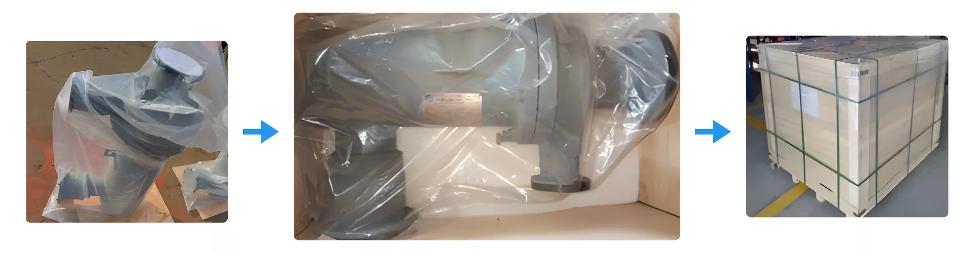
Packaging Process for Silicon Carbide Lined Internal Gear Pump

Silicon Carbide Lined Internal Gear Pump is protected through a multi-stage packaging process designed to prevent moisture exposure, vibration, and structural impact during transport. Each pump is first sealed in a corrosion-resistant plastic wrap, then cushioned inside a reinforced wooden crate to stabilize the unit during long-distance shipment. The final palletized configuration ensures safe handling and maintains crate integrity throughout global freight operations.

ADCERAX® Packaging of SiC Lined Pump

Application Scenarios for SiC Lined Internal Gear Pumps

Silicon carbide lined internal gear pumps are commonly reviewed for systems that handle abrasive, viscous or chemically aggressive fluids. These applications often involve contaminated lubricants, long working cycles, fluctuating loads or corrosive process media, where SiC contact parts may help reduce wear on exposed pump surfaces.

  • Hydraulic Systems with Contaminated Oils

    In hydraulic power units, metal fines from valves, cylinders or bearing surfaces can increase internal wear in conventional gear pumps. A SiC lined internal gear pump can be considered when the system requires more stable internal geometry under abrasive oil circulation.

    For this application, buyers should provide oil type, contamination condition, working pressure, flow demand, filtration level and duty cycle before pump selection.

  • Lubrication Circulation for Gearboxes and Rolling Equipment

    Large lubrication circuits often operate with high-viscosity oils and long running cycles. When lubricant aging, thermal load or particle contamination causes pump wear or unstable output, SiC contact parts may help protect wear surfaces and maintain more predictable flow behavior.

    Key review points include viscosity range, oil temperature, required flow rate, bearing or gearbox load condition, filtration method and installation layout.

  • Resin, Polymer and Heavy-Oil Transfer

    Resins, polymers, bitumen and heavy oils can combine viscosity, chemical activity and residue formation. A SiC lined internal gear pump may be used when the process requires controlled transfer of difficult fluids while reducing wear on internal contact surfaces.

    Before quotation, ADCERAX reviews media composition, solid content, operating temperature, cleaning method, sealing requirement and whether the fluid may cure, crystallize or polymerize during operation.

Usage Notes for SiC Lined Internal Gear Pumps

The SiC lined internal gear pump requires proper installation, commissioning and routine monitoring to support stable fluid transfer in abrasive, viscous or chemically aggressive media. This guide helps users reduce startup stress, avoid dry running and maintain consistent pump performance during long-duty operation.

  • Installation Requirements for Reliable Startup

    1. Check shaft alignment and pipe support.
    The pump should be installed with proper shaft alignment and stable piping support. Misalignment, unsupported piping or excessive external load can increase bearing stress, seal wear and internal contact risk.

    2. Confirm priming before operation.
    The pump should be fully primed before startup. Dry running may damage the SiC seal faces, bushings and wear surfaces, especially when handling viscous or particle-containing fluids.

    3. Verify inlet conditions.
    The inlet line should be clean, properly sized and free from blockage. Poor suction conditions can cause cavitation, unstable flow, noise and additional wear inside the pump.

  • Commissioning Steps for First-Time Operation

    1. Start under controlled conditions.
    Begin operation at a low speed or reduced load when possible. Confirm flow direction, inlet pressure, outlet pressure and seal condition before continuous operation.

    2. Monitor temperature and noise.
    During initial running, check for abnormal temperature rise, vibration, noise or leakage. These signs may indicate poor alignment, insufficient priming, unsuitable viscosity or excessive internal resistance.

    3. Confirm fluid compatibility.
    The fluid temperature, viscosity, particle content and chemical composition should match the selected pump configuration. If the media condition changes, the pump selection should be reviewed again.

  • Operating Practices for Continuous Performance

    1. Maintain stable filtration.
    Filters should be checked and cleaned regularly to reduce particle buildup. Stable filtration helps protect SiC wear plates, bushings and seal faces from excessive abrasive exposure.

    2. Avoid sudden pressure fluctuation.
    Rapid pressure changes can increase load on the gear set, housing and sealing area. The system should be operated within the reviewed pressure range and protected from frequent pressure spikes.

    3. Track flow and pressure changes.
    A gradual drop in flow rate or unstable pressure may indicate increased viscosity, inlet restriction, seal wear or internal clearance changes. Early monitoring helps prevent extended operation under unsuitable conditions.

  • Maintenance Intervals and Long-Term Care

    1. Schedule routine inspection.
    Inspection intervals should be based on fluid type, particle condition, temperature, operating pressure and duty cycle. Abrasive or corrosive media usually require closer monitoring than clean lubricating fluids.

    2. Check seal and wear components.
    Seal faces, bushings and wear plates should be inspected when leakage, noise, vibration or flow instability appears. Replacement decisions should be based on actual wear condition, not only running time.

    3. Store the pump correctly.
    If the pump is not used for an extended period, it should be cleaned, dried and protected from moisture, dust and corrosive residues. Proper storage helps reduce corrosion risk and startup problems after reinstallation.

FAQs: Silicon Carbide Lined Internal Gear Pump

  1. Q1: What fluids are suitable for a silicon carbide lined internal gear pump?

    A silicon carbide lined internal gear pump is commonly considered for abrasive, viscous or chemically aggressive fluids, including hydraulic oils, lubricating oils, resins, polymers, bitumen, heavy oils and selected process media. Final suitability depends on the fluid composition, viscosity, temperature, particle condition, sealing requirement and duty cycle.

  2. Q2: How does SiC lining help when the fluid contains abrasive particles?

    Silicon carbide contact parts provide high hardness and wear resistance on surfaces exposed to particles or contaminated oils. This helps reduce scoring on wear plates, bushings and chamber contact areas. However, particle size, concentration, filtration level and operating pressure still need to be reviewed before pump selection.

  3. Q3: Can this pump handle high-viscosity media?

    Internal gear pumps are often used for controlled transfer of viscous fluids. For a SiC lined version, ADCERAX reviews the minimum, normal and maximum viscosity under operating temperature, along with flow rate, motor power, suction condition and pipe layout. This helps confirm whether the pump can maintain stable transfer without excessive load.

  4. Q4: Is a SiC lined internal gear pump suitable for corrosive fluids?

    SiC contact parts can be useful in corrosion-prone media, but the complete pump configuration must be reviewed together with seals, housing materials, elastomers and metal parts. Buyers should provide the fluid name, concentration, temperature and cleaning method so the material compatibility can be checked before quotation.

  5. Q5: What information should I provide for quotation?

    Please provide the required flow rate, working pressure, fluid type, viscosity range, temperature range, particle condition, sealing requirement, port size, installation layout and duty cycle. If this is a replacement project, drawings, photos, nameplate data or existing pump model information are also helpful.

  6. Q6: Can ADCERAX customize the pump according to my existing system?

    Yes. ADCERAX can review custom requirements for pump model selection, SiC contact parts, seal pairing, port arrangement, mounting interface, drive connection and replacement matching. The final design should be confirmed after reviewing the operating media and installation conditions.

customize size

Custom Configuration Options for SiC Lined Internal Gear Pumps

ADCERAX supports drawing-based and application-based customization for SiC lined internal gear pumps. The configuration can be reviewed according to the working media, flow rate, pressure, viscosity, temperature, particle condition and installation interface.

Available customization items may include pump model selection, SiC contact parts, seal face materials, port size, inlet and outlet direction, mounting interface, drive connection, surface treatment and inspection requirements. For replacement projects, customers can provide drawings, photos, nameplate information or existing pump parameters for engineering review.

Custom Item Available Review Direction
SiC Contact Parts Chamber liner, wear plate, bushing and seal face configuration.
Seal Configuration SiC/SiC, carbon/SiC or other seal pairing based on media condition.
Port Layout Inlet/outlet size, thread type, flange interface and flow direction.
Drive Connection Motor, coupling and mounting interface review.
Surface Finish Contact surface finish selected according to sealing and wear requirements.
Replacement Matching Existing pump dimensions, nameplate, drawings or samples can be reviewed.

Related Products

ADCERAX - Your Trusted Advanced Ceramics Manufacturing Partner

Direct factory manufacturing with comprehensive ceramic materials expertise and global supply capabilities

China-Based Manufacturer

ADCERAX supplies ceramic components for overseas OEMs, equipment builders, and labs.

Custom Drawing Support

We review drawings, dimensions, materials, and application conditions before quotation.

Ceramic Process Control

Forming, sintering, machining, grinding, and finishing are arranged by part requirements.

Pre-Shipment Inspection

Dimensional checks, visual inspection, and packaging review help reduce procurement risk.

Get in Touch with Us

Our team will be happy to respond to you in less than 24 hours.

Pingxiang Factory — Silicon carbide, silicon nitride, high-temperature ceramics

Quick Quotation

*Our team will answer your inquiries within 24 hours.

*Your information will be kept strictly confidential.

Ready to Solve Your Engineering Challenge?

Partner with ADCERAX for reliable, high-performance advanced ceramic solutions. Our engineers are ready to discuss your project.

E-mail

info@adcerax.com

Phone

+(86) 0731-74427743 | WhatsApp: +(86) 19311583352

Response Time

Within 24 hours

Quick Quote

The more details you provide, the faster we can quote.

*We respond within 24 hours. All inquiries are confidential.

Get Your Custom Solution

The more details you provide, the faster we can respond.

customize size

*We respond within 24 hours. All inquiries are confidential.

Download Catalog