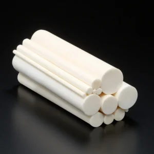
ADCERAX ZTA ceramic rods are designed for industrial assemblies where alumina may chip, metal may wear or corrode, and full zirconia may be unnecessary. They provide a practical balance of hardness, fracture toughness, electrical insulation and dimensional stability for shafts, locating pins, seal supports, guide rods and hot-zone fixtures.
For custom projects, ADCERAX reviews rod diameter, length, straightness, end geometry, surface finish, mating parts and operating conditions before quotation. This helps confirm material suitability and the key machining details needed for stable production.
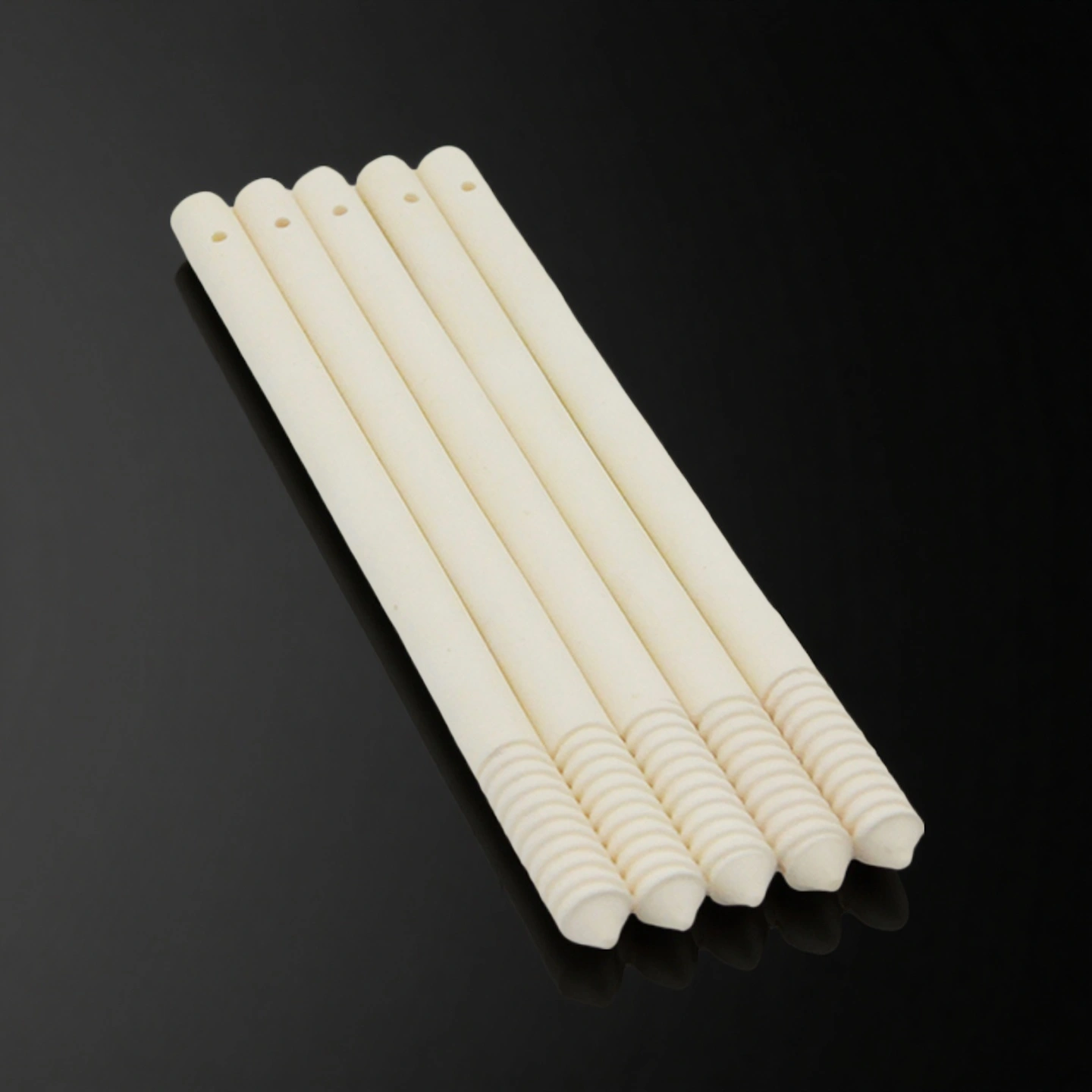
Catalog No.
AT-ZR-B001
Material
85-90% Al2O3 + 10-15% ZrO2
Fracture Toughness (KIC)
≥5.0–7.0 MPa·m½
Vickers Hardness (HV10)
~1,300–1,600
Available Dimensions
Standard OD Ø2–30 mm; custom length, bore, chamfer and stepped designs by drawing review
Zirconia Toughened Alumina (ZTA) rod is a structural ceramic made from an alumina (Al₂O₃) matrix dispersed with zirconia (ZrO₂) particles. The zirconia is stabilized (often yttria-stabilized) so that, when microcracks start, zirconia particles transform and expand at the crack tip (transformation toughening). This arrests crack growth and gives the rod higher fracture toughness than pure alumina while keeping high hardness and wear resistance.
ZTA Ceramic Rod Advantages for Industrial Assemblies
Improved Edge Stability During Assembly
ZTA rods are often selected when alumina rods have a risk of edge chipping during press-fit, clamping, handling or repeated installation. The zirconia toughening phase helps slow crack growth, which is useful for small shafts, locating pins and rod ends with chamfers or precision-ground edges.
Wear-Resistant Rod Surfaces for Sliding or Locating Contact
For guide rods, sealing pins and positioning shafts, surface wear can change clearance and alignment over time. A ground or polished ZTA rod can help maintain a stable contact surface in abrasive, dry-sliding or lightly lubricated assemblies where metal rods may score, corrode or generate particles.
Balanced Material Choice Between Alumina and Zirconia
ZTA is useful when standard alumina is too brittle for the assembly condition, but full zirconia may be unnecessary for cost, temperature or stiffness reasons. This makes ZTA rods suitable for applications that need stronger toughness than alumina while keeping good hardness and insulation behavior.
Custom Geometry for Functional Fit
ADCERAX can review rod features such as OD, length, flat section, groove, through-bore, chamfer, radius, stepped end and polished contact zone. These details matter because ceramic rods usually fail from stress concentration, poor edge design or incorrect mating clearance rather than from material strength alone.
Inspection-Oriented Supply for Repeat Orders
For repeatable industrial use, the most important values are not only material properties but also controlled diameter, straightness, surface finish, end quality and lot traceability. ADCERAX® can define key inspection points based on the drawing and the rod’s function in the assembly.
ZTA Ceramic Rods Properties
The following values are typical reference properties for material comparison. Final values may vary by grade, forming method, sintering condition and machining requirement.
Property
Unit
Alumina (99%)
ZTA (Zirconia Toughened Alumina)
Y-TZP Zirconia
Fracture Toughness (KIC)
MPa·m¹⁄²
5
7 – 9
6 – 10
Vickers Hardness
HV10
1600-1800
1400-1600
1100-1300
Flexural Strength
MPa
400
650 – 800
800 – 1200
Density
g/cm³
3.9
4.0 – 4.3
6.0
Relative Wear Rate
—
1.0
0.45 – 0.55
0.2
Thermal Expansion Coefficient (RT – 800 °C)
×10⁻⁶ /K
8.0
8.5 – 9.0
10 – 11
Thermal Conductivity (RT)
W/m·K
25
22 – 24
2 – 3
Maximum Working Temperature
°C
1600
1450 – 1500
1000 – 1200
Dielectric Strength
kV/mm
12
11 – 13
9 – 11
Surface Roughness (Ground face)
µm Ra
0.4 – 1.2
0.3 – 0.8
0.2 – 0.6
Flatness (after grinding)
mm/300 mm
≤ 0.4
≤ 0.3
≤ 0.2
Zirconia Toughened Alumina Rods Specifications
ZTA Rods
Item No.
Diameter(mm)
Length (mm)
AT-ZR-B001
1
15-1000
AT-ZR-B002
2
15-1000
AT-ZR-B003
3
15-1000
AT-ZR-B004
4
15-1000
AT-ZR-B005
5
15-1000
AT-ZR-B006
6
15-1000
AT-ZR-B007
7
15-1000
AT-ZR-B008
8
15-1000
AT-ZR-B009
9
15-1000
AT-ZR-B010
10
15-1000
AT-ZR-B011
11
15-1500
AT-ZR-B012
12
15-1500
AT-ZR-B013
13
15-1500
AT-ZR-B014
14
15-1500
AT-ZR-B015
15
15-1500
AT-ZR-B016
16
15-1500
AT-ZR-B017
17
15-1500
AT-ZR-B018
18
15-1500
AT-ZR-B019
19
15-1500
AT-ZR-B020
20
15-1500
AT-ZR-B021
21
15-1500
AT-ZR-B022
22
15-1500
AT-ZR-B023
23
15-1500
AT-ZR-B024
24
15-1500
AT-ZR-B025
25
15-1500
AT-ZR-B026
26
15-1500
AT-ZR-B027
27
15-1500
AT-ZR-B028
28
15-1500
AT-ZR-B029
29
15-1500
AT-ZR-B030
30
15-1500
AT-ZR-B031
31
15-1500
AT-ZR-B032
32
15-1500
AT-ZR-B033
33
15-1500
AT-ZR-B034
34
15-1500
AT-ZR-B035
35
15-1500
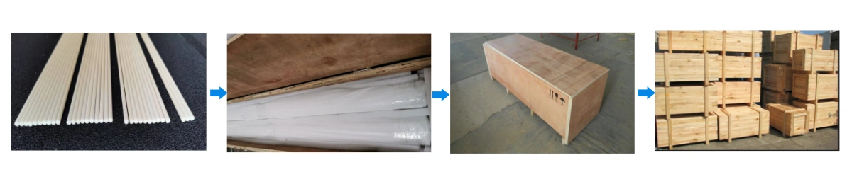
ZTA Rods Packaging
ZTA ceramic rods are packed to reduce edge chipping, bending stress, surface scratches and mixed-size confusion during international transport.
Each rod is wrapped or placed in foam slots, plastic tubes or separated trays according to diameter, length and surface finish.
Ground or polished rods are protected from loose metal parts, abrasive dust and direct contact with other rods.
Different diameters and item numbers are separated to reduce mixing risk during incoming inspection.
Long or fragile rods are packed with reinforced outer cartons or wooden cases when needed.
ZTA Ceramic Rod Applications
ZTA ceramic rods are used in industrial assemblies where the rod must provide wear resistance, dimensional stability and improved edge toughness under mechanical contact. Compared with standard alumina rods, ZTA rods are often selected when the part is exposed to assembly pressure, vibration, sliding contact, repeated positioning or moderate impact risk. The following application areas show how the material can support practical engineering decisions.
Pump and Valve Pins
ZTA ceramic rods can be used as guide pins, wear pins, valve pins, seal supports or small shaft elements in pumps and valves handling abrasive, corrosive or particle-containing media. In these assemblies, metal pins may suffer from corrosion, surface scoring or clearance change, while standard alumina pins may chip if the seat design or assembly force is not well controlled.
The zirconia toughened alumina structure helps provide a harder and more wear-resistant contact surface while offering better resistance to edge damage than conventional alumina. This makes ZTA rods suitable for designs where stable alignment, reduced wear debris and longer sealing contact life are important. For pump or valve use, the rod diameter, chamfer, mating seat, sliding condition and medium compatibility should be reviewed before production.
Precision Locating Pins and Guide Rods
In automation fixtures, inspection equipment, assembly jigs and positioning systems, ZTA ceramic rods can serve as locating pins or guide rods that maintain repeatable position under mechanical contact. The material is useful when stainless steel or tool steel pins may wear, deform, corrode or contaminate the part surface after repeated use.
ZTA rods are especially suitable when the locating surface must remain hard, smooth and electrically insulating. Ground or polished surfaces can help reduce friction and support more consistent contact with mating components. For precision locating applications, buyers should define the OD tolerance, straightness, end shape, surface finish and whether the rod will be fixed, sliding, replaceable or exposed to side load.
Ceramic Shafts for Sliding or Rotating Interfaces
ZTA ceramic rods may be used as ceramic shafts in light-duty sliding, rotating, metering or adjustment mechanisms. These applications usually require a rod surface that can resist abrasion, maintain clearance and avoid corrosion in contact with process media or cleaning chemicals. ZTA provides a useful balance when alumina is too brittle for the assembly condition and full zirconia is not necessary for the working load.
When used as a shaft, the rod should be evaluated together with the bearing material, seal material, lubricant, contact pressure and expected speed. A polished ZTA surface can reduce counterface wear in selected designs, but the mating material must still be checked carefully. Unsupported bending loads, sharp shoulders and poor alignment should be avoided because ceramic shafts remain sensitive to tensile stress and impact.
Furnace Fixture and Hot-Zone Support Rods
ZTA ceramic rods can be used as support rods, spacer rods, insulating rods or positioning members in selected furnace fixtures and hot-zone assemblies. They are useful when the design requires better chipping resistance than standard alumina while still needing ceramic insulation, hardness and dimensional stability under repeated heating cycles.
In furnace-related applications, ZTA rods may support small fixtures, separate components, hold alignment or reduce direct metal contact in heated areas. The final material choice should consider working temperature, thermal cycling speed, atmosphere, load direction and whether the rod is constrained by metal hardware. For high thermal shock or very aggressive furnace conditions, alumina, zirconia or silicon carbide alternatives may also need to be compared.
Electrical Insulating Rods in Mechanical Assemblies
ZTA ceramic rods can function as insulating support rods, standoffs or alignment members in mechanical assemblies that require both structural support and electrical separation. They can help isolate conductive parts while providing higher wear resistance and improved edge toughness compared with many standard insulating ceramics.
This application is common in equipment where the rod is not only an insulator but also a mechanical positioning element. Buyers should review creepage distance, clearance, contact pressure, mounting method and operating temperature before selecting the rod size. If the rod will be clamped by metal parts, the fixture should avoid point loading and allow enough clearance for thermal expansion differences.
Wear Rods for Abrasive Contact Areas
ZTA ceramic rods can also be used as wear rods or replaceable contact elements in equipment exposed to repeated rubbing, abrasive particles or guide contact. Instead of replacing a larger assembly, the ceramic rod can be designed as a controlled wear component that protects the surrounding metal or polymer structure.
This approach is useful when the contact area is narrow, cylindrical or difficult to protect with a flat ceramic plate. The rod can be ground to the required diameter and installed as a sleeve-supported or mechanically retained component. For this type of design, the installation method, counterface material, impact risk and replacement access should be considered during the drawing review stage.
ZTA Ceramic Rod Usage Instructions
Installation
1. Check rod diameter, length, straightness, chamfer and end condition before assembly. Do not force a ceramic rod into a metal seat if the interference or alignment has not been reviewed.
2. Use soft jaws, polymer pads or supported fixtures when clamping the rod. Point loading from hard metal tools can create small edge defects that later grow during operation.
3. For press-fit or shrink-fit designs, review ceramic-to-metal expansion difference, interference value and edge chamfer before production. A small design change at the rod end can significantly reduce chipping risk.
Operation
1. Keep bending, side impact and cantilever loading as low as possible. ZTA improves toughness compared with alumina, but it remains a ceramic material and should not be treated like steel.
2. For sliding contact, confirm counterface hardness, surface finish, lubrication condition and particle contamination. Incorrect counterface design can increase wear even when the ceramic rod itself is suitable.
3. In heated assemblies, avoid sudden thermal shock, direct flame impingement and strong temperature gradients unless the fixture design has been validated.
Cleaning
1. Clean rods with lint-free cloth, DI water, alcohol or approved process cleaning methods. Dry the rods fully before storage or assembly.
2. Avoid cleaning methods that may attack the alumina phase, contaminate the surface or damage polished contact zones.
Storage and Transport
1. Store ZTA rods in padded trays, foam slots or separated tubes. Long rods should be supported along their length to reduce bending stress during handling.
2. Keep precision-ground or polished rods away from metal hardware, abrasive dust and loose parts that may scratch the surface during transport.
ZTA Ceramic Rod FAQ
What is a ZTA ceramic rod used for?
A ZTA ceramic rod is used as a wear-resistant shaft, locating pin, guide rod, seal support, insulating rod or furnace fixture member in industrial assemblies. It is selected when standard alumina may chip under assembly stress, while metal rods may wear, corrode or lose electrical insulation.
When should I choose ZTA rods instead of alumina rods?
Choose ZTA rods when the part must handle impact during installation, vibration, sliding contact, repeated assembly or edge-sensitive loading. Alumina rods are still suitable for many stable insulating or high-hardness applications, but ZTA is often safer when toughness and chipping resistance are more important.
Can ZTA rods replace zirconia ceramic rods?
ZTA rods can replace zirconia rods in selected applications where full zirconia toughness is not required and the design benefits from higher hardness, better stiffness or a more cost-controlled material choice. The replacement should be reviewed according to temperature, load, chemical medium, counterface material and required tolerance.
Are ZTA ceramic rods suitable for high-temperature use?
ZTA rods can be used in selected high-temperature fixtures and insulating supports, but the safe temperature depends on grade, load, atmosphere, rod size and thermal cycling. For furnace applications, the design should avoid sharp temperature gradients, direct flame impact and unsupported bending loads.
Can ZTA rods be drilled, grooved or threaded?
ZTA rods can be made with grooves, bores, flats, chamfers or stepped features when the geometry is reviewed before manufacturing. Complex holes or threads should be confirmed early because dense sintered ceramics are difficult to machine after firing, and some features are safer when formed or pre-machined before final sintering.
How do I choose the right ZTA rod diameter and length?
The correct diameter and length depend on load direction, span, bending risk, fit clearance, straightness requirement and how the rod is supported in the assembly. Long, thin rods require special attention to straightness, packaging and installation support to reduce breakage risk.
What information should I send for a ZTA rod quotation?
Please send the drawing, OD, length, tolerance, surface finish, quantity, working temperature, chemical medium, load condition, mating part material and whether the rod will be clamped, pressed, bonded, sliding or used in a hot zone. This information helps confirm material suitability and machining feasibility before quotation.
For custom ZTA rods and ZTA ceramic shafts, please specify the geometry, tolerance, surface finish and operating conditions needed for fit, friction control and temperature exposure. ADCERAX can review the rod design according to the drawing, assembly method and working environment before quotation.
Outer and Inner Diameter
Standard OD: Ø2–30 mm. Custom sizes beyond this range can be reviewed according to the drawing.
Typical tolerance bands: ±0.01–0.03 mm for OD ≤10 mm, and ±0.02–0.05 mm for OD >10 mm.
Concentricity for bored rods can be reviewed to ≤0.02 mm, depending on size, length and machining feasibility.
Length and Straightness
Cut-to-length rods can be reviewed up to 1,500 mm per piece.
Straightness control for long shafts can target ≤0.02 mm / 100 mm when the rod size and grinding process allow.
End Geometry
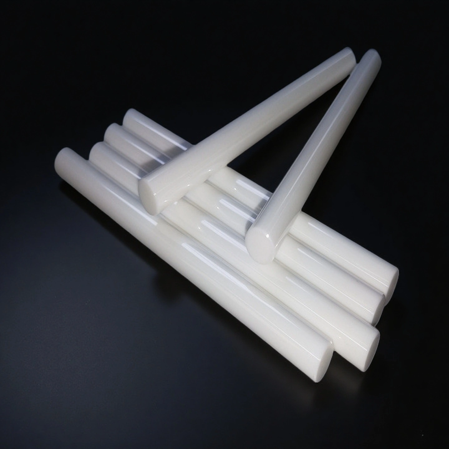
Available end designs may include square-cut ends, 45° chamfers, radiused ends and hemispherical tips.
Typical chamfer options include 0.2–0.5 mm, while radius options may range from R0.2 to R1.0 depending on rod size.
Fixture-related features such as flats, anti-rotation faces, center holes and counterbores can be reviewed by drawing.
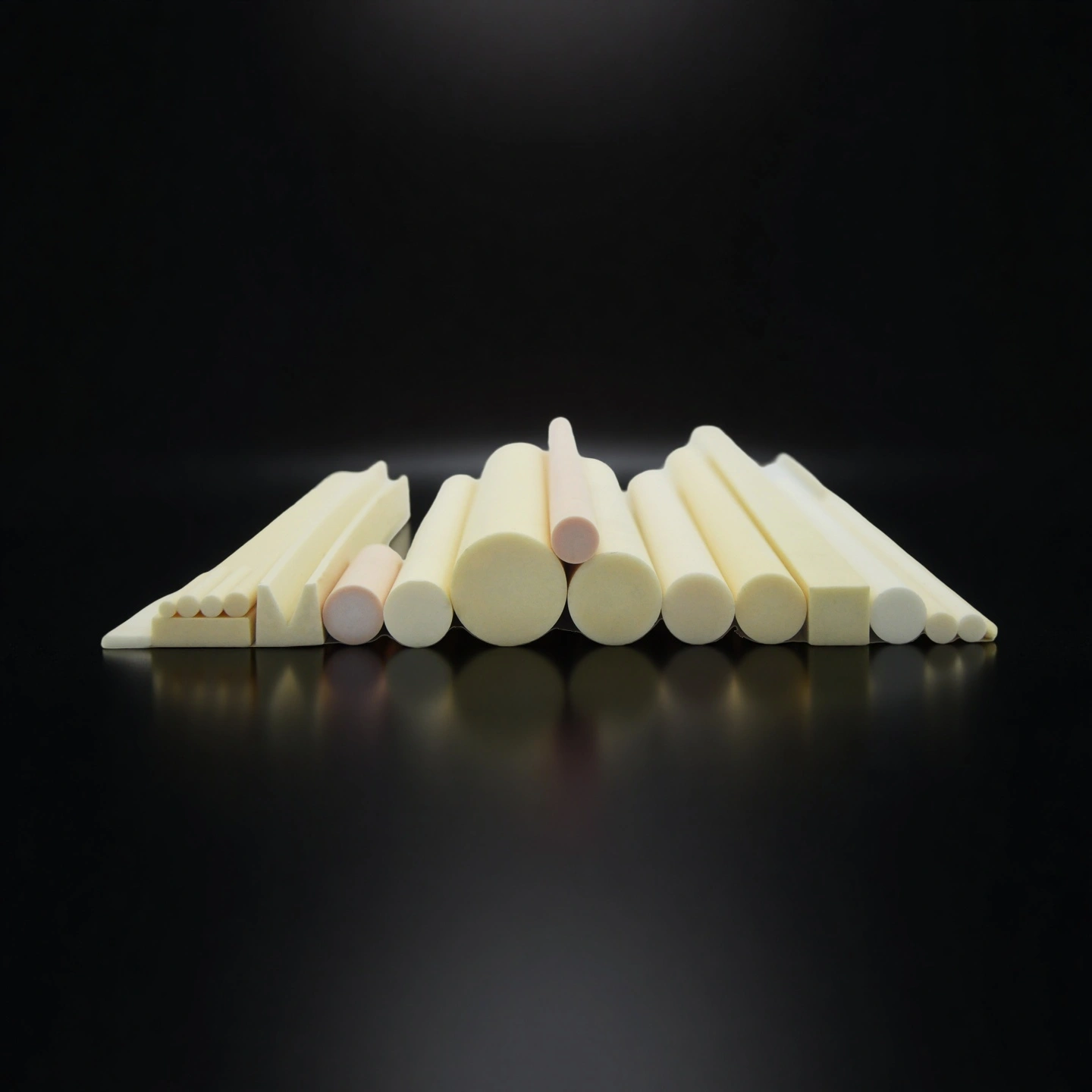
Cross-Section and Functional Features
Available structures may include solid rods, through-bore rods, stepped OD rods, key flats, seal grooves and pin holes.
Pre-sinter shaping or post-sinter grinding can be selected according to strength, tolerance and feature complexity.
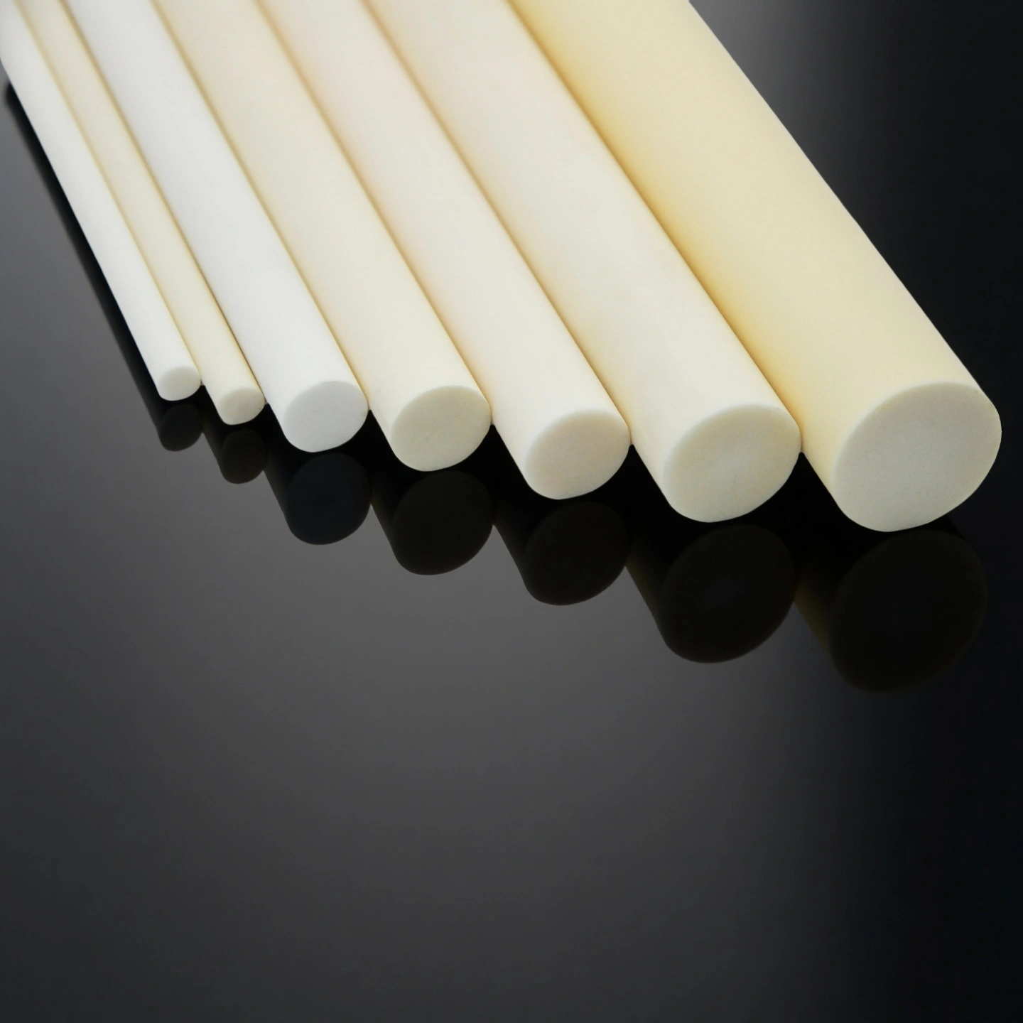
Surface Finish Options
As-fired surfaces are suitable for non-critical fits or support positions.
Ground OD surfaces are recommended for bearing, locating, sliding or seal-contact interfaces.
Polished surfaces can reach Ra ≤0.2 µm in selected cases where low friction and reduced counterface wear are required.
Micro-bead blasted bonding surfaces can be reviewed for adhesive joining or improved bonding contact.
Material Grade Choices
ZrO₂ content can be selected according to toughness, wear resistance and high-temperature stability requirements.
Typical ZrO₂ content options may range from 10–20 vol%, depending on the final grade and application review.
Electrical-insulation grade and wear-focused grade can be reviewed according to the operating condition.
Fit and Tolerance Guidance
For ceramic-to-metal press-fit designs, interference should be verified by stack-up tolerance, temperature change and assembly method.
A reference interference range of about 5–15 µm per 10 mm OD may be reviewed, but final values must be confirmed by the actual design.
Adding a 0.2–0.5 mm 45° chamfer on press-fit ends can help reduce edge chipping risk.
For sliding seal applications, a counterface finish of Ra ≤0.2–0.4 µm is usually preferred to reduce friction and wear.
Please provide the drawing, OD, ID if required, length, tolerance, surface finish, quantity, working temperature, medium, load direction, mating material and assembly method. These details help confirm whether ZTA is suitable and which machining process should be used.