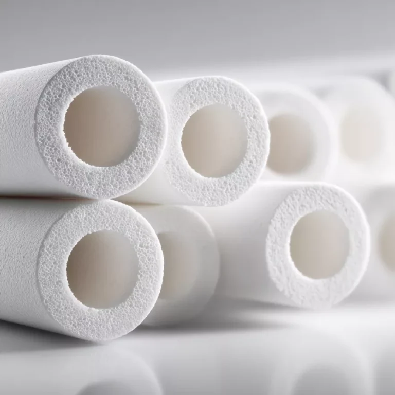


What Is a Porous Silicon Carbide Vacuum Chuck?
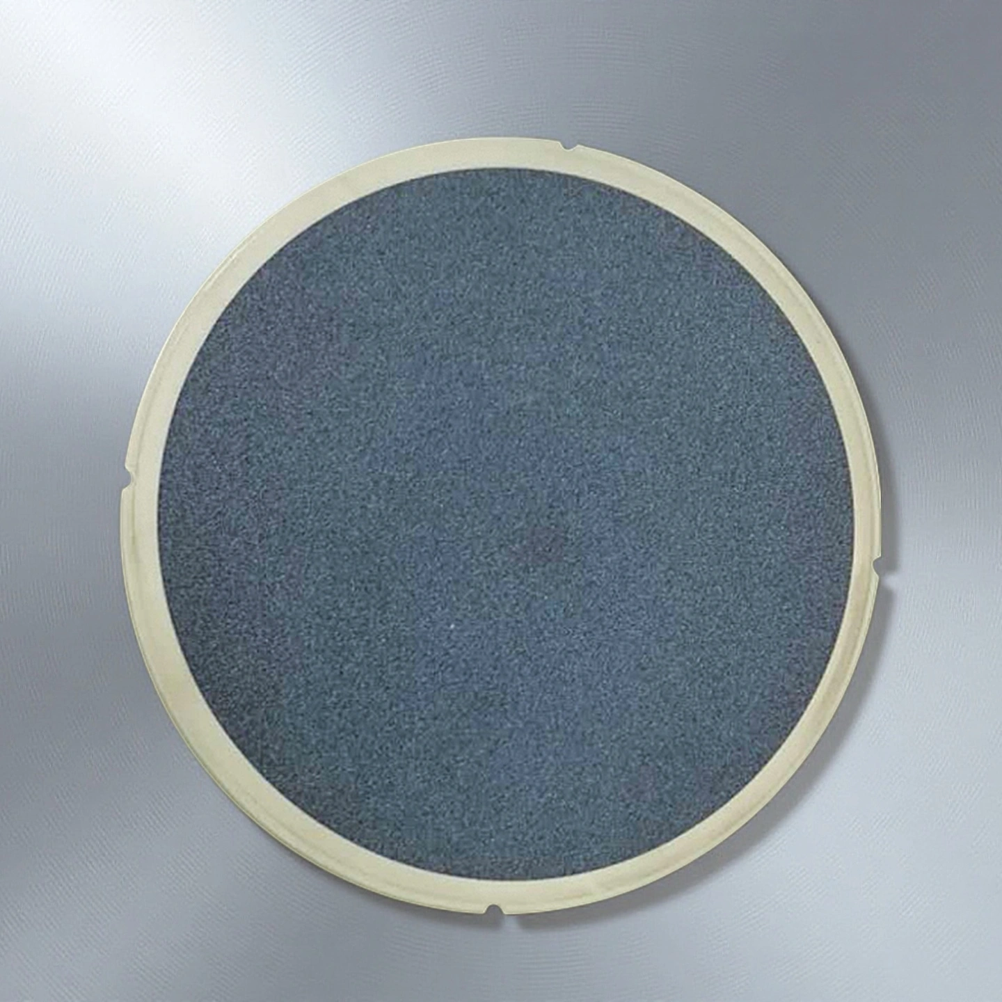
A porous silicon carbide vacuum chuck is a precision ceramic holding component that uses an interconnected microporous structure to distribute vacuum force across a contact surface. Instead of relying on a small number of suction holes, the porous SiC surface allows more uniform airflow, which helps stabilize thin, fragile or lightweight substrates during automated handling.
This type of vacuum chuck is used in equipment where substrate flatness, surface cleanliness, thermal stability and repeatable positioning are important. Typical applications include photovoltaic cell transfer, wafer handling equipment, thin glass alignment, electronics substrate transfer, inspection fixtures and automated pick-and-place systems.
Compared with metal vacuum plates, porous silicon carbide offers higher hardness, better wear resistance, lower thermal deformation and stronger resistance to many cleaning chemicals. Compared with alumina, SiC can provide better thermal conductivity and stronger performance in high-cycle handling environments where both suction uniformity and dimensional stability matter.
Performance Factors That Affect Porous SiC Vacuum Chuck Selection
The performance of a porous silicon carbide vacuum chuck depends on pore structure, surface finish, vacuum channel design, flatness and equipment alignment. These factors should be reviewed together because suction stability, substrate protection and long-term cleanability are affected by both the ceramic material and the equipment interface.
-
Pore Structure
It affects airflow response, suction distribution and clogging resistance. -
Vacuum Channel Design
It helps balance vacuum force across the porous contact area. -
Surface Finish
It should match the sensitivity of wafers, PV cells, thin glass or electronics substrates. -
Flatness Control
It supports stable contact and repeatable positioning during transfer or inspection. -
Edge Treatment
It helps reduce contact risk when handling thin or fragile substrates. -
Cleaning Method
It affects long-term pore stability and vacuum consistency.
Porous Silicon Carbide vs Alumina, Metal and Graphite Vacuum Plates
| Material Option | Strength | Limitation | When Porous SiC Is Better |
|---|---|---|---|
| Aluminum or stainless steel plate | Easy machining and low initial cost. | Wear, thermal expansion and surface deformation may increase over time. | Use porous SiC when long-cycle dimensional stability and wear resistance matter. |
| Alumina porous plate | Good insulation and ceramic stability. | Lower thermal conductivity and lower toughness than SiC in some handling designs. | Use SiC when thermal stability, hardness and repeated handling performance are important. |
| Graphite plate | Good machinability and thermal performance. | Particle generation, oxidation and surface contamination may be concerns. | Use SiC when cleanliness, chemical resistance and wear control are required. |
| Porous silicon carbide chuck | High hardness, low thermal expansion, chemical stability and controlled suction distribution. | Requires proper pore design, machining control and cleaning method. | Best suited for demanding substrate handling where suction uniformity and surface stability are critical. |
Material and Performance Reference for Porous SiC Vacuum Chucks
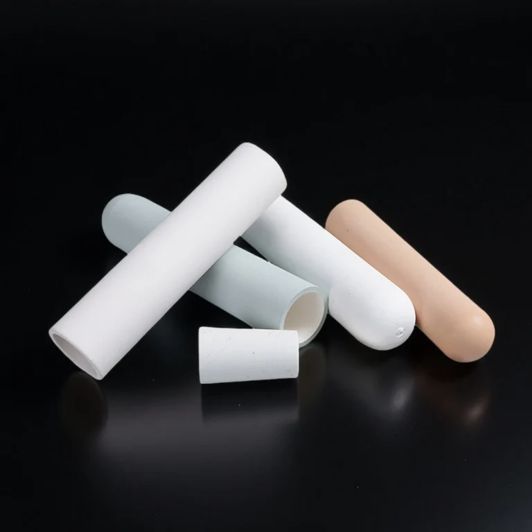
The Porous Silicon Carbide Vacuum Chuck is engineered with controlled microporosity, high thermal endurance, and stable mechanical performance suitable for semiconductor, photovoltaic, and precision electronic handling environments. Its material structure supports long-cycle operation under elevated temperatures, chemical exposure, and continuous vacuum load conditions.
| Property | Specification |
|---|---|
| Material Composition | Recrystallized SiC, purity >98% |
| Sintering Temperature | >2000 °C recrystallization |
| Bulk Density | 2.75–3.05 g/cm³ |
| Open Porosity | 10–18% controlled pore ratio |
| Pore Size Range | 2–20 μm engineered micro-pore distribution |
| Flexural Strength | >250 MPa |
| Compressive Strength | >900 MPa |
| Hardness | Mohs ~9 |
| Thermal Conductivity | 80–120 W/m·K |
| Coefficient of Thermal Expansion | 4.0×10⁻⁶ /K (25–800 °C) |
| Maximum Service Temperature | >1500 °C in inert and vacuum atmospheres |
| Chemical Resistance | Stable against acids, alkalis, and cleaning chemicals |
| Surface Roughness (Ra) | 0.4–1.2 μm finish optional |
| Airflow Uniformity Deviation | Within ±5% |
| Particle Generation | Ultra-low shedding, suitable for clean handling |
Dimensions of Porous Silicon Carbide Vacuum Chuck
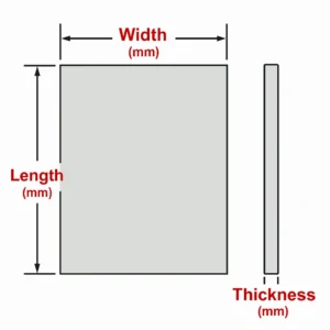
| Square SiC Vacuum Chuck | ||||
| Item No. | Length(mm) | Width(mm) | Thickness(mm) | Material |
| AT-THG-XP001 | 305 | 305 | 14 | 316 stainless steel + microporous ceramic |
| AT-THG-XP002 | 305 | 305 | 14 | 316 stainless steel + microporous ceramic |
| AT-THG-XP003 | 420 | 275 | 20 | Aluminum alloy + microporous ceramic |
| AT-THG-XP004 | 450 | 200 | 20 | SKD61 + porous ceramic |
| AT-THG-XP005 | 520 | 520 | 20 | Aluminum alloy + microporous ceramic |
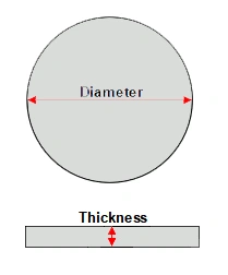
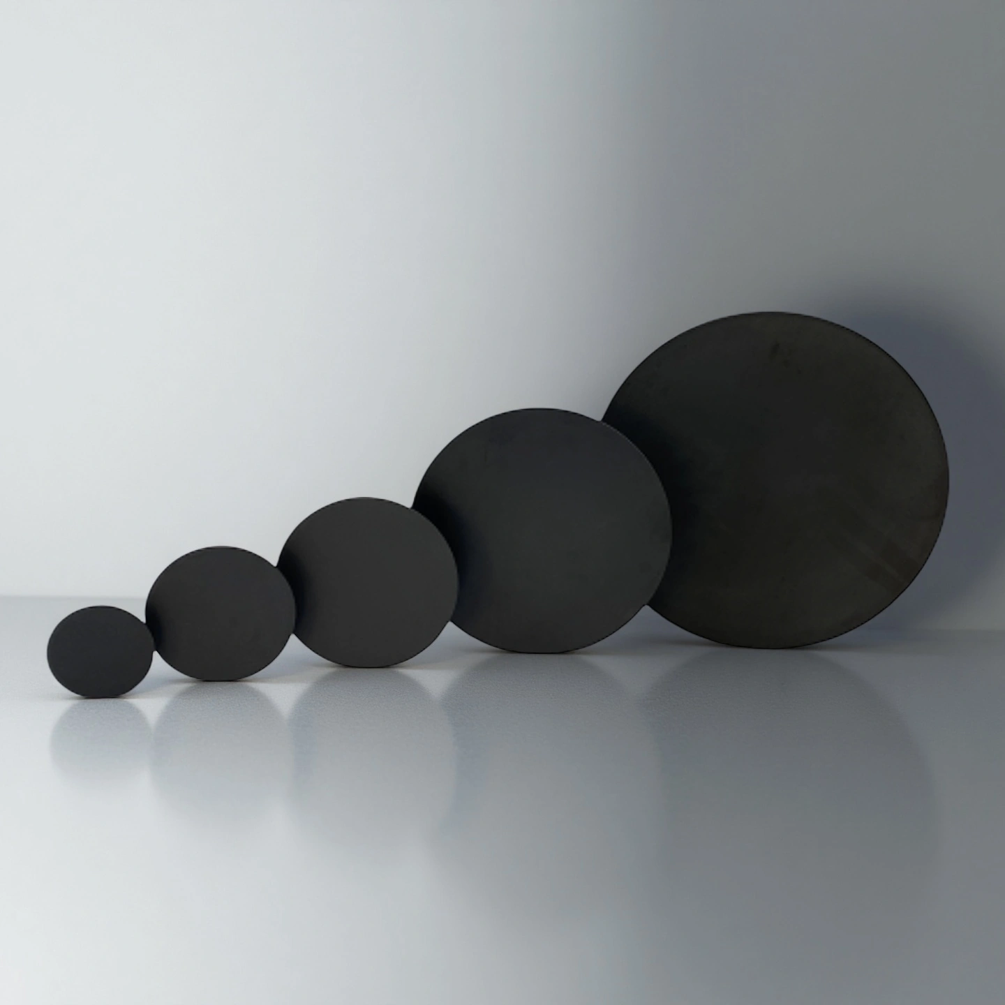
| Round SiC Vacuum Chuck | |||
| Item No. | Diameter(mm) | Thickness(mm) | Material |
| AT-THG-XP006 | 174 | 10 | 316 stainless steel + microporous ceramic |
| AT-THG-XP007 | 230 | 16 | 316 stainless steel + microporous ceramic |
| AT-THG-XP008 | 239 | 12 | Aluminum alloy + microporous ceramic |
| AT-THG-XP009 | 240 | 12 | 316 stainless steel + microporous ceramic |
| AT-THG-XP010 | 320 | 16 | 316 stainless steel + microporous ceramic |
| AT-THG-XP011 | 325 | 12 | Aluminum alloy + microporous ceramic |
Engineering Challenges Solved by Porous SiC Vacuum Chucks
| Handling Challenge | Production Risk | How Porous SiC Helps |
|---|---|---|
| Thin substrates are easily cracked during lifting. | Local vacuum peaks may create edge stress or bending. | Controlled microporosity spreads suction more evenly across the contact area. |
| Vacuum force becomes unstable during fast transfer. | Substrates may slip, tilt or shift during robotic movement. | Balanced pore and channel design supports repeatable airflow response. |
| Metal plates wear or deform after long operation. | Surface flatness and adsorption consistency may drift. | Silicon carbide provides high hardness and strong dimensional stability. |
| Cleaning residues block pores or channels. | Adsorption force becomes inconsistent across the chuck surface. | Proper pore design and cleaning access reduce clogging risk. |
| Heated process zones cause fixture distortion. | Alignment accuracy and handling repeatability may decline. | SiC has low thermal expansion and good thermal stability. |
| Fragile glass or coated substrates are easily scratched. | Surface marks may cause downstream optical or inspection failure. | Controlled surface finish and edge treatment help reduce contact damage. |
Technical Design Factors for Porous SiC Vacuum Chuck Performance
The performance of a porous SiC vacuum chuck depends on the balance between pore structure, vacuum distribution, flatness, surface finish and substrate sensitivity. Before production, ADCERAX reviews how the chuck will contact the wafer, PV cell, glass sheet or electronics substrate, because small changes in pore design or vacuum layout can affect suction stability and handling safety.
| Design Factor | Why It Matters |
|---|---|
| Pore size and porosity | It affects suction uniformity, airflow response and clogging resistance. |
| Vacuum channel layout | It determines whether vacuum force is balanced across the chuck surface. |
| Surface flatness | It affects substrate contact, positioning stability and handling repeatability. |
| Surface finish | It helps reduce scratches, local pressure points and particle retention. |
| Substrate thickness | It determines how much vacuum force the part can safely tolerate. |
| Cleaning method | It affects long-term pore stability and suction consistency. |
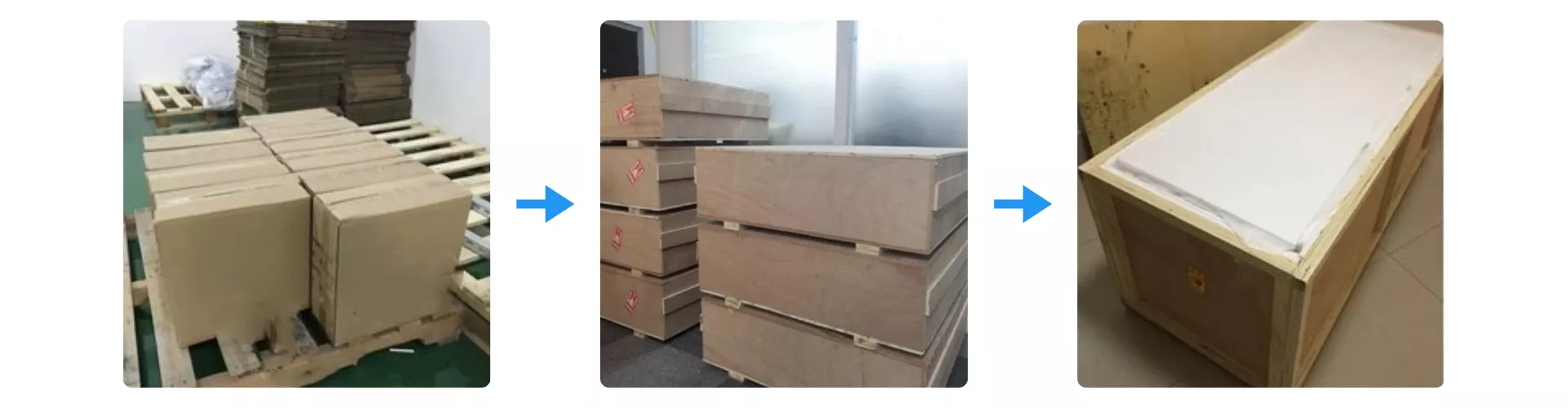
Packaging for Porous Silicon Carbide Vacuum Chuck
Porous Silicon Carbide Vacuum Chuck is packed using a multi-layer protection process designed to prevent vibration, moisture exposure, and handling stress during international transport. Each unit is first cushioned and boxed, then reinforced with solid wooden crates to ensure structural stability throughout shipment. This packaging method supports safe delivery to equipment manufacturers and assembly facilities requiring intact, contamination-free ceramic components.