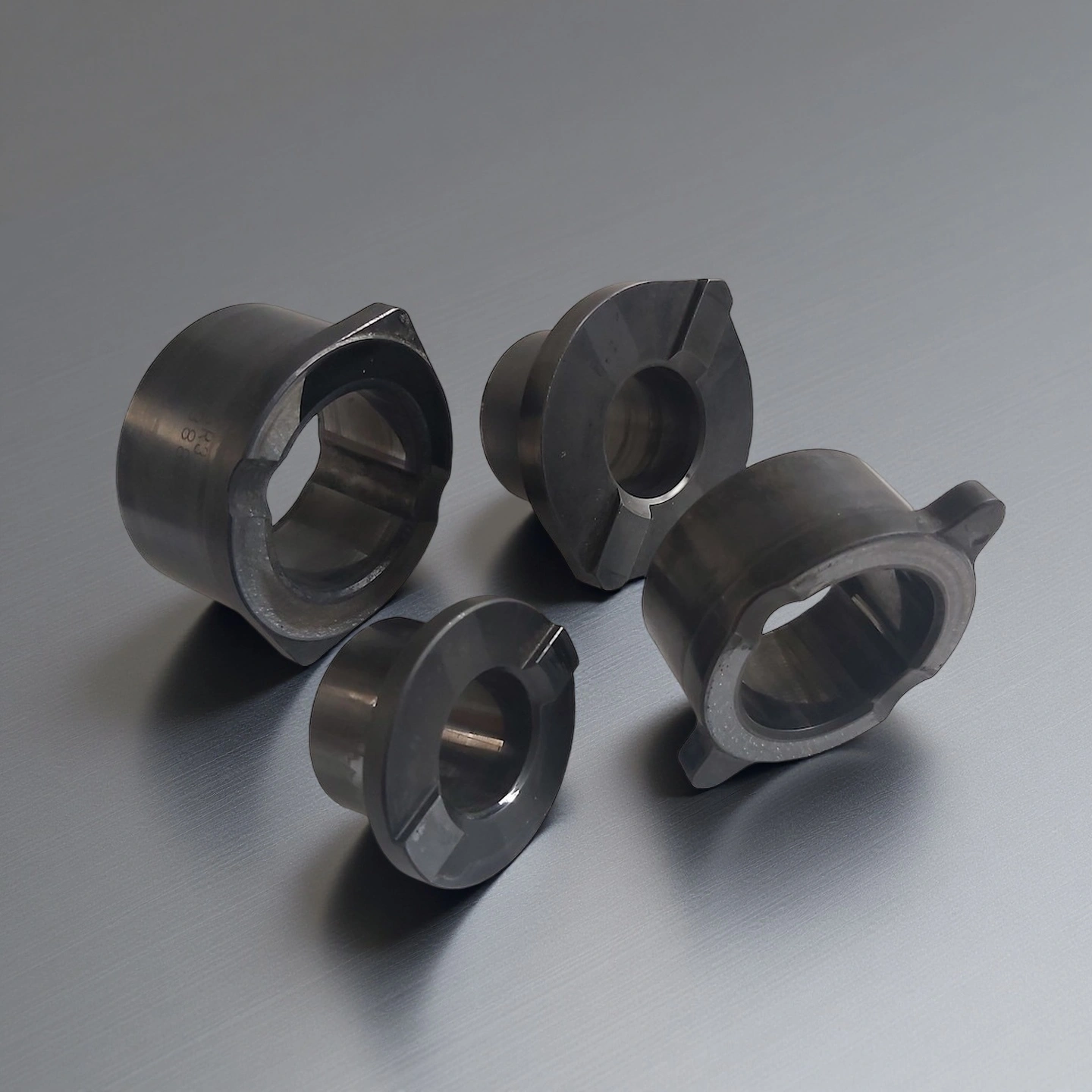
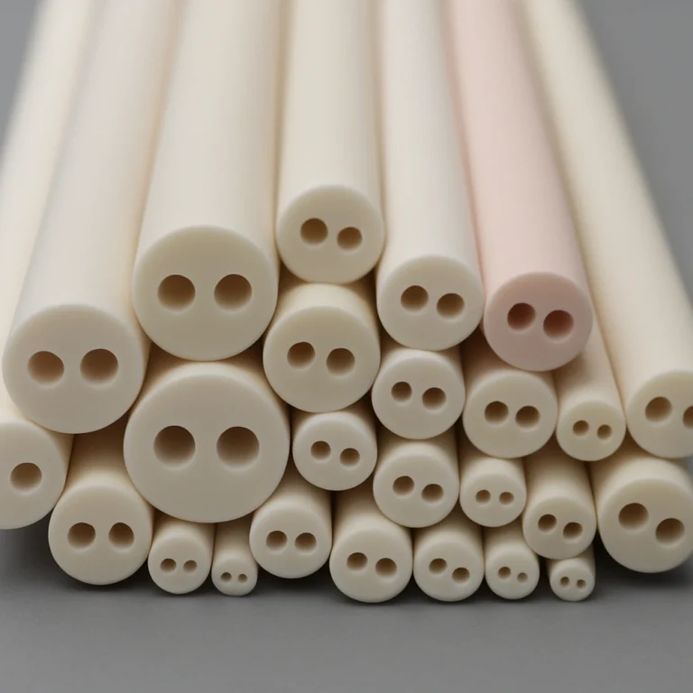
Reinforced Silicon Carbide Liner Tube for Industrial Flow Systems
ADCERAX® Silicon Carbide Liner Tube is customized through engineered design pathways that align its geometry, surface attributes, and microstructural behavior with the mechanical, thermal, and chemical conditions present in industrial flow and wear environments.
Catalogue No.
AT-SIC-TT1001
Material
Silicon Carbide (RBSiC / SSiC)
Hardness
>23 GPa wear resistance in high-velocity slurry service
ADCERAX® Silicon Carbide Liner Tube is engineered for continuous operation in abrasive, corrosive, and high-temperature flow environments where metallic and oxide-based liners experience rapid degradation. Its stable microstructure, high hardness, and chemical resistance support long service intervals in industrial systems handling slurry transport, corrosive chemical media, or fiber-laden pulp mixtures. These characteristics enable reliable performance across mining, chemical processing, pulp and paper operations, and thermal-energy facilities that depend on durable lining materials to maintain operational continuity.
Advanced Material Performance of Silicon Carbide Liner Tube
Consistent Erosion Behavior The fine-grain SiC microstructure minimizes grain pull-out, reducing mass-loss rates by over 60% compared with high-chrome steel in standardized slurry abrasion tests. Such stability allows predictable performance in pump discharge zones where impact frequency often surpasses 10⁶ collisions per hour.
Structural Strength Under Operational Stress Flexural strength values exceeding 380 MPa allow the tube to withstand cyclic mechanical impact common in mechanical housings and slurry transport lines. This strength level contributes to reduced fracture occurrence in zones where pressure fluctuations can surpass 10–20 bar.
Resistance to Chloride-Rich and Organic Media Performance remains stable in chloride environments with ion concentrations above 5,000 ppm, supporting reliability in desalination side streams and chemical brine plants. Exposure tests also show negligible mass change (<0.1%) in mixed organic solvents commonly used in petrochemical transfer systems.
Technical Specifications of Silicon Carbide Liner Tube
ADCERAX® Silicon Carbide Liner Tube exhibits a stable microstructure, high mechanical strength, and strong thermal and chemical endurance suitable for long-cycle industrial operation in abrasive, corrosive, and high-temperature environments.
Property
Specification
Material Type
RBSiC / SSiC
Density
3.05–3.15 g/cm³
Hardness
>23 GPa (Vickers)
Flexural Strength
>380 MPa
Compressive Strength
>2,000 MPa
Thermal Conductivity
>110 W/m·K
Thermal Expansion (RT–1000°C)
4.0–4.5 ×10⁻⁶ /K
Maximum Service Temperature
>1,300°C
Open Porosity
<1%
Acid Resistance
Stable in 20–30% H₂SO₄ / HCl
Alkali Resistance
Stable up to pH 12
Chloride Compatibility
Stable up to >5,000 ppm Cl⁻
Slurry Abrasion Loss
<40% of high-chrome steel
Grain Size
5–10 μm (fine-grain SiC)
Electrical Resistivity
10⁵–10⁶ Ω·cm
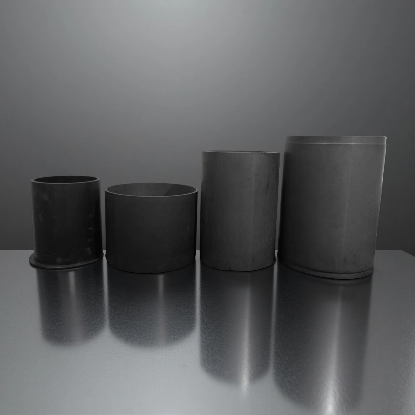
Dimensions of Silicon Carbide Liner Tube
SiC Liner
Item No.
Diameter(mm)
Height (mm)
AT-SIC-TT1001
Customize
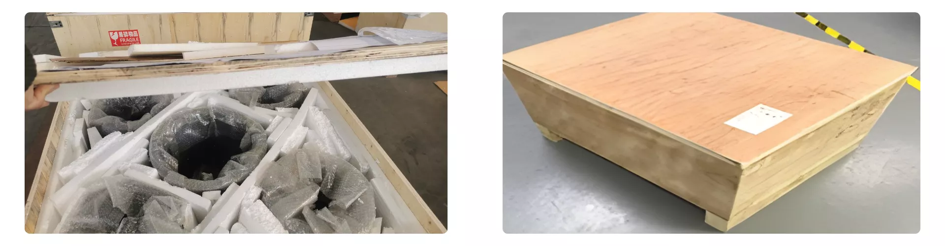
Protective Packaging for Silicon Carbide Liner Tube
Silicon Carbide Liner Tube is securely packed using multi-layer foam cushioning and full-coverage bubble wrapping to prevent impact, vibration, or surface abrasion during long-distance transport. Each component is individually immobilized within a reinforced plywood crate to ensure stable positioning throughout handling and shipment. The sealed export-grade wooden case provides additional protection against moisture, stacking pressure, and mechanical stress during international delivery.
ADCERAX® Silicon Carbide Liner Tube Solves Critical Wear, Corrosion, and Thermal Challenges in Heavy-Duty Industrial Systems
Industrial operators relying on abrasive slurries, corrosive chemical media, or high-temperature material transfer face recurring failures in steel, polymer, and oxide-ceramic liners. ADCERAX® Silicon Carbide Liner Tube addresses these issues by offering stable mechanical performance, high thermal endurance, and long-term corrosion resistance across complex, high-load operating environments.
Silicon Carbide Liner Tube in High-Velocity Slurry Transport Lines for Mineral Concentration Plants
✅Key Advantages
1. Impact-zone wear stabilization ADCERAX® Silicon Carbide Liner Tube maintains internal diameter loss below 0.3 mm after extended exposure to high-velocity slurry in elbow and discharge regions. In the same duty, high-chrome steel sections typically reach more than 1.0 mm wall loss within a comparable operating interval, forcing early replacement.
2. Consistent performance with variable slurry density Field monitoring shows that wear-rate variation remains within ±15% even when slurry density is increased by more than 20%, which is common during peak throughput campaigns. This stability helps sustain predictable maintenance windows in plants where ore hardness and particle size distribution fluctuate day by day.
3. Controlled friction and pressure drop evolution In concentration circuits retrofitted with ADCERAX® Silicon Carbide Liner Tube, measured pressure-drop growth over a campaign can be limited to less than 10%. Conventional metallic liners in the same lines often exhibit pressure-drop increases above 30% as internal roughness rapidly develops under angular particle impact.
✅ ️Problem Solved
In a hard-rock copper concentrator, slurry transfer lines from the grinding circuit to the cyclones previously relied on metallic liners that reached critical wall loss within roughly one quarter of a typical annual operating cycle. As wear accelerated around elbows and pump outlets, operators recorded unstable pressure profiles and frequent adjustments to cyclone feed conditions, which negatively affected separation efficiency. After replacing these sections with ADCERAX® Silicon Carbide Liner Tube, inspection data over one full campaign showed wall-thickness loss reduced by more than half and pressure-drop drift kept within a narrow operating band. The plant was able to extend planned liner replacement intervals from a single campaign to multiple campaigns while maintaining stable feed conditions to the classification stage and reducing unplanned maintenance interventions.
Silicon Carbide Liner Tube in Chloride-Rich and Acidic Transfer Loops of Chemical Production Units
✅Key Advantages
1. Acid–chloride stability in elevated temperature service ADCERAX® Silicon Carbide Liner Tube remains structurally stable in mixed acid systems with concentrations in the 20–30% range and operating temperatures above 80°C. In comparable environments, alloy steel liners typically show rapid pitting and wall thinning once temperature and chloride content exceed their recommended limits.
2. Minimal mass loss and low contamination release Laboratory exposure tests in chloride-rich acidic media have reported cumulative mass loss below 0.1% for silicon carbide samples after extended immersion. This low material loss significantly reduces the introduction of foreign ions or particulate contamination into sensitive process streams that feed downstream synthesis or purification steps.
3. Resilience under repeated cleaning and thermal cycling ADCERAX® Silicon Carbide Liner Tube tolerates hundreds of acid-cleaning and heating cycles without measurable change in microstructure or surface integrity when evaluated by weight loss and microscopy. In contrast, polymer-based and metallic liners often show visible surface degradation after dozens of such cycles, requiring premature replacement and system flushing.
✅ ️Problem Solved
A chemical production unit handling mixed acid and chloride brines in its recirculation loop had experienced repeated liner failures in sections exposed to cleaning acids and hot process liquor. Metallic liners developed localized pits and thinning, and polymer liners showed softening and surface cracking after limited thermal and chemical cycling, which led to unstable impurity levels in the reaction feed. After installing ADCERAX® Silicon Carbide Liner Tube in the high-load sections of the loop, periodic inspections over multiple operating campaigns indicated negligible pitting and mass loss, and analytical data showed a marked reduction in contamination events attributed to liner materials. As a result, the plant extended planned maintenance intervals, reduced the frequency of emergency line flushes, and maintained more consistent reaction conditions in its downstream processing steps.
Silicon Carbide Liner Tube in Fiber-Laden Slurry and Caustic Recovery Systems of Pulp & Paper Mills
✅Key Advantages
1. Abrasion resistance in fiber and black-liquor streams In pulp transfer lines carrying fiber suspensions and black liquor, ADCERAX® Silicon Carbide Liner Tube has demonstrated internal thickness loss below 0.2 mm over extended operating periods. Comparable metallic liners in the same positions frequently exceed 0.6 mm thickness loss under the combined action of fibers, dissolved solids, and entrained particles.
2. Stability in hot caustic and recovery circuits The liner material maintains surface integrity in caustic recovery solutions operating at pH values up to 12 and temperatures in the 90–130°C range. Under these conditions, polymer-based linings often exhibit softening, dimensional change, or surface cracking, which can accelerate wear once suspended solids begin to attack weakened regions.
3. Reduced roughness growth and energy penalties Surface roughness measurements on ADCERAX® Silicon Carbide Liner Tube sections show limited roughness increase, with Ra remaining within 20–30% of the as-installed value after long-term service. This behavior supports more stable hydraulic performance, whereas roughened metallic or polymer liners can drive pumping energy requirements noticeably higher as internal friction progressively increases.
✅ ️Problem Solved
In a kraft pulp mill, transfer lines between the digester and washing stages experienced rapid degradation of metallic and polymer liners exposed to hot fiber slurry and caustic solutions. Internal surfaces became rough and uneven within a relatively short period, forcing the mill to increase pumping power and carry out frequent liner replacements to avoid leaks and flow instabilities. After installing ADCERAX® Silicon Carbide Liner Tube in the critical segments of the pulp and caustic transfer system, follow-up inspections showed significantly lower roughness growth and much slower wall-thickness loss than with previous materials. Over subsequent operating cycles, the mill reported more stable flow rates, fewer liner-related interventions, and improved predictability in its planned maintenance scheduling for these sections.
How to Use ADCERAX® Silicon Carbide Liner Tube Safely and Effectively in Demanding Industrial Systems
Silicon Carbide Liner Tube is best utilized when operators follow stable installation, handling, and operational practices that preserve its mechanical integrity, ensure predictable performance, and extend service cycles under abrasive, corrosive, and high-temperature conditions.
Pre-Installation Handling and Inspection Guidelines
1. Initial Material Verification Operators should confirm that each liner arrives without visible cracking, chipping, or surface deformation after unpacking. A short incoming inspection helps identify accidental impact damage that may occur during freight handling. Ensuring structural integrity at this stage prevents hidden defects from propagating once the liner is pressurized.
2. Surface Cleanliness Check Before installation, the inner surface should be kept clear of dust, slurry residues, or foreign particles that may affect early-stage flow conditions. Any contamination can introduce abrasive interaction during the first operating hours. Maintaining a clean internal surface helps achieve stable friction behavior from the beginning.
3. Environmental Conditioning When moving the liner from storage into a warm or humid operating hall, the tube should be allowed to reach ambient equilibrium. Sudden temperature or humidity transitions can cause local condensation on the inner wall. Avoiding condensation reduces the risk of particle adhesion during startup.
Installation Recommendations for Stable Mechanical Integration
1. Support and Alignment Control The liner should be mounted using fixtures designed to distribute load evenly along the outer surface. Uneven stress concentration may lead to microcrack development during vibration or pressure cycling. A uniform support structure preserves long-term mechanical integrity.
2. Joint Sealing and Interface Preparation Connection points must be fitted with compatible seals or gaskets that tolerate the same chemical and thermal environment as the liner itself. Improper sealing can introduce bypass flow or turbulence at the joint interface. Proper sealing helps maintain consistent flow behavior throughout the circuit.
3. Avoiding Excessive Clamp Force Clamping devices must be adjusted according to recommended force limits to prevent point loading on the ceramic surface. Excessive compression may cause premature fracture during pressure surges. Controlled fastening significantly reduces the risk of installation-related failures.
Operational Best Practices Under Abrasive, Corrosive, or Thermal Loads
1. Gradual Ramp-Up Procedures During system startup, it is recommended to increase flow velocity and temperature progressively to allow the liner to adapt to initial gradients. A sudden load jump may induce localized stress that affects long-term stability. Smooth ramp-up helps maintain structural consistency over repeated cycles.
2. Monitoring of Slurry or Chemical Composition Operators should track shifts in slurry density, particle size, or chemical concentration, as abrupt changes can alter wear mechanisms inside the tube. Continuous monitoring helps detect conditions that accelerate abrasion or corrosion. Stable operating conditions directly extend lining service intervals.
3. Flow Disturbance Observation Any unexpected vibration, pressure drop, or pulsation should be investigated promptly to avoid compounding internal stress. Early detection of flow instability helps prevent excessive impact loading on the liner wall. Timely intervention mitigates progressive wear.
Maintenance, Inspection, and Replacement Interval Planning
1. Scheduled Internal Surface Assessment Periodic borescope checks or surface inspection routines should be performed depending on slurry abrasiveness or chemical harshness. These inspections allow early identification of surface roughening or minor wall loss. Routine assessment prevents unplanned system shutdowns.
2. Cleaning Practices for Long-Term Stability Cleaning cycles must avoid abrasive brushing or overly aggressive chemical agents that can introduce unnecessary surface fatigue. Controlled flushing or compatible chemical cleaning methods are preferred. Appropriate cleaning preserves the liner’s microstructure.
3. Replacement Strategy Optimization Replacement intervals should be planned using historical wear data and monitored operating variables rather than fixed schedules. Adopting a data-driven replacement strategy ensures cost efficiency while preventing premature failures. Predictive maintenance maximizes lifecycle value.
Q1: How does the Silicon Carbide Liner Tube maintain stability under continuous abrasive slurry impact? The Silicon Carbide Liner Tube maintains surface integrity because its hardness exceeds 23 GPa, preventing rapid material removal under angular particle flow. This allows the internal geometry to stay consistent during long-duty cycles in mineral processing pipelines. As a result, pressure fluctuations and flow disruption are reduced across impact-intensive pipe sections. Its stability directly mitigates premature liner failure observed with metallic and oxide-based materials.
Q2: Why does the Silicon Carbide Liner Tube outperform metal liners in corrosive chloride or acid environments? The tube’s inert chemical structure remains unaffected by concentrated acids, chloride-bearing brines, or mixed aggressive media. This prevents pitting, wall thinning, and contamination commonly seen with steel or alloy liners exposed to chemical cycling. Even during high-temperature cleaning operations, its microstructure remains unchanged. This durability supports consistent reaction purity and stable process chemistry.
Q3: What enables the Silicon Carbide Liner Tube to resist combined abrasion and chemical attack in pulp and paper systems? Its material exhibits simultaneous resistance to fiber-induced abrasion and hot alkaline solutions, conditions that quickly degrade polymers and metals. The tube retains a smooth internal surface, minimizing turbulence and energy loss during pulp transfer. Its chemical inertness prevents surface softening over long periods. This capability directly stabilizes caustic recovery loops where multiple degradation mechanisms coexist.
Q4: How does the Silicon Carbide Liner Tube handle rapid thermal cycling in high-temperature plant operations? The tube’s low thermal expansion and high thermal conductivity reduce stress concentration during abrupt temperature shifts. This prevents cracking and distortion common in liners subjected to start-stop thermal cycles. Its microstructure remains stable above elevated operating temperatures in power and waste-to-energy facilities. This resilience improves uptime and reduces refractory maintenance cycles.
Q5: Why is the Silicon Carbide Liner Tube suitable for long-length or large-diameter lining applications? Its high flexural strength supports rigid structural behavior even when produced in extended lengths. This rigidity prevents deformation under internal pressure fluctuations or mechanical vibration. Its wear resistance ensures consistent performance across the entire tube span. This allows engineers to deploy longer continuous liners without frequent joint failures.
Engineering Community Feedback on ADCERAX® Silicon Carbide Liner Tube in Real Industrial Operations
⭐️⭐️⭐️⭐️⭐️
The Silicon Carbide Liner Tube demonstrated remarkable wear stability under fluctuating slurry loads, outperforming alloy-based liners previously used in our mineral concentration circuit. Its ability to maintain a consistent internal surface profile significantly reduced pressure variability across multiple campaigns. We observed measurable improvements in flow uniformity and reduced intervention frequency throughout continuous operation. — M. Turner, Process Engineering Division, North Ridge Minerals
⭐️⭐️⭐️⭐️⭐️
In our chloride-rich chemical recirculation loop, the Silicon Carbide Liner Tube delivered exceptional resistance to acid–chloride attack, even under elevated temperatures and frequent cleaning cycles. The material showed negligible mass change during periodic inspection, contributing to consistent process purity. Its stability improved downstream reaction performance and reduced the need for corrective maintenance. — L. Schneider, Engineering Materials Group, Helvotec Chemicals
⭐️⭐️⭐️⭐️⭐️
Our pulp handling and caustic recovery systems benefited from the tube’s strong abrasion–corrosion synergy resistance, especially in zones with high fiber loading and temperature fluctuations. Surface roughness remained low over extended runtime, reducing energy consumption and maintaining predictable pumping behavior. Its resilience supported stable throughput and extended maintenance intervals. — D. Morales, Technical Operations Unit, Alpine Pulp Systems
⭐️⭐️⭐️⭐️⭐️
During continuous service in mixed abrasive and corrosive environments, the Silicon Carbide Liner Tube showed consistent structural integrity under multi-variable operating stress, including rapid temperature changes and particle-size variability. This reliability was critical for maintaining operational uptime in our process circuits. The installation proved materially advantageous compared with prior metallic and oxide-based liners. — S. Gallagher, Mechanical Engineering Team, Westfield Industrial Solutions
ADCERAX® Silicon Carbide Liner Tube is configured through engineered customization pathways designed to match the structural, thermal, and corrosion-exposed conditions encountered across heavy-duty industrial systems.
Structural Geometry Customization
Specialized geometric adaptations are applied to enhance alignment, flow behavior, and mechanical stability under demanding load conditions.
End-Form Interfaces configured joints ensuring precise assembly fit
Surface and Microstructure Customization
Surface and microstructural refinements are implemented to strengthen durability against abrasive particles, corrosive media, and thermal cycling effects.
Surface Finish Control polished textures reducing friction levels
Pore-Phase Optimization modified porosity improving chemical resistance
Micro-Grain Adjustment refined grain distribution enhancing wear stability