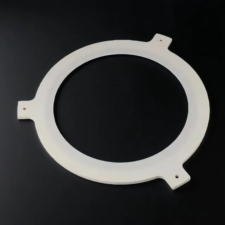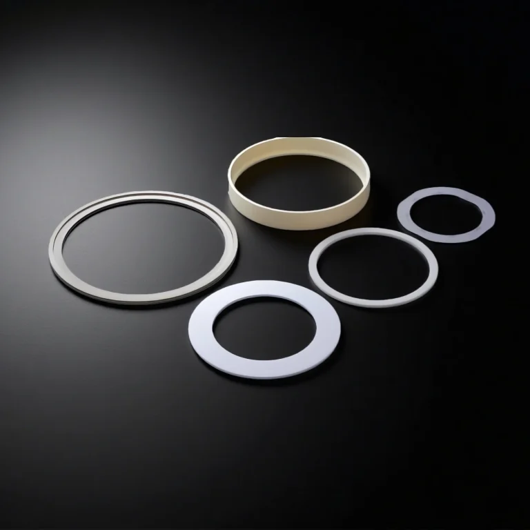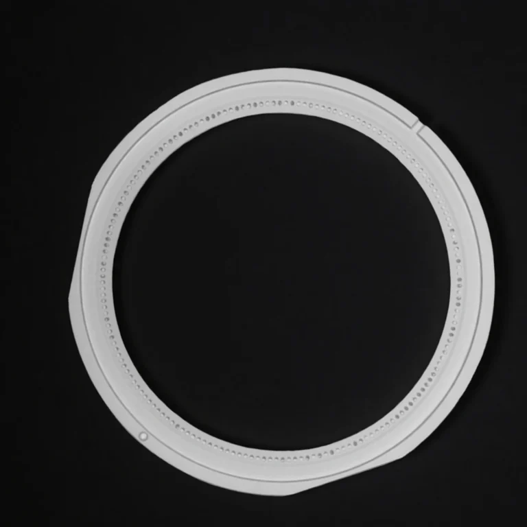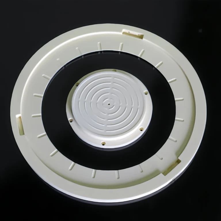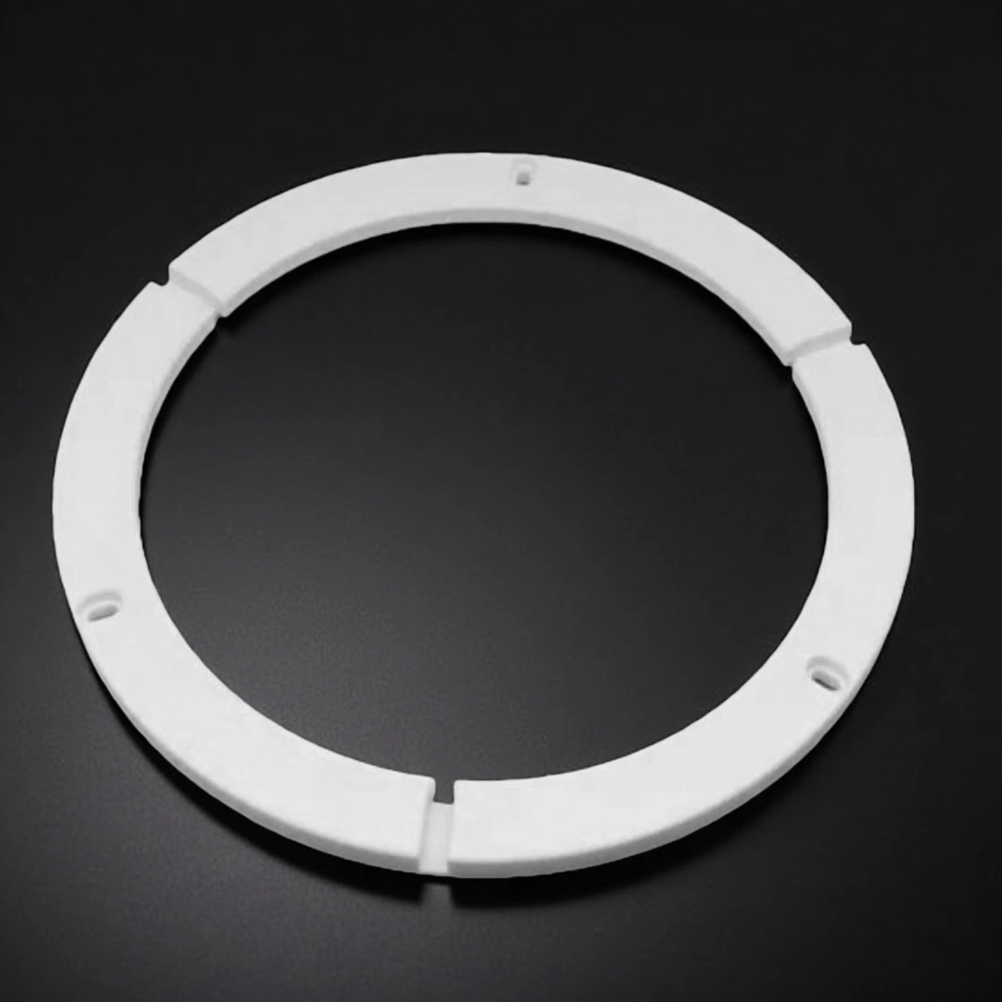
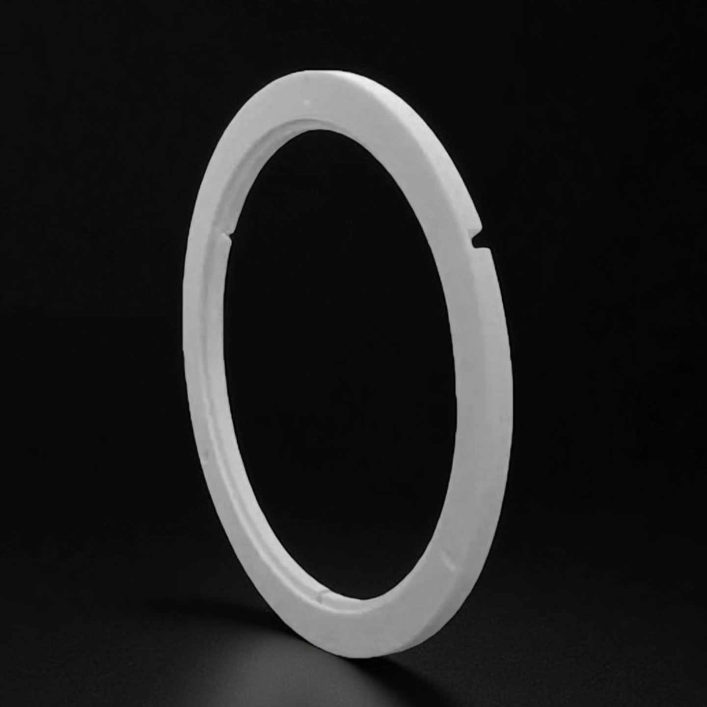
A High Purity Alumina Edge Ring is a dense, high-purity Al₂O₃ ceramic ring installed inside plasma or vacuum process chambers to define the process boundary, protect nearby hardware, and stabilize edge-zone behavior by using controlled ring geometry (OD/ID, steps, chamfers, radii) and dielectric isolation.
High Purity Alumina Edge Ring Benefits
-
Boundary-geometry control: engineered chamfer/radius/step profiles define a stable edge-zone boundary, helping keep the active plasma region where the chamber design intends. A controlled edge profile also reduces sensitivity to small assembly differences between maintenance cycles, so edge behavior stays repeatable after rebuilds.
-
Dense body for stability: a high-density alumina body supports consistent mechanical integrity under repeated clamp/seat cycles and thermal cycling typical of vacuum process tools. Dense structure helps lower the risk of micro-chipping at edges and contact faces, which is critical for parts that are frequently removed and reinstalled.
-
Dielectric isolation by design: high volume resistivity supports electrical stability around the edge-zone region, which is important when the ring sits near powered components or field gradients. Consistent dielectric behaviour helps reduce unintended coupling changes after part replacement, improving process repeatability without re-tuning the chamber every time.
-
Low damage risk edges: controlled edge finish (defined corner-break, chamfer, and deburring) reduces chip initiation during handling, installation, and cleaning. This is especially valuable for thin lip features or stepped designs, where sharp corners can crack under point contact during maintenance.
-
Fit-critical interface control: OD/ID and seating features are treated as functional interfaces, not just dimensions. Tight control of datums, concentricity, and contact-face condition helps the ring seat without rocking, maintains alignment with adjacent shields or fixtures, and reduces the chance of uneven wear patterns over time.
-
Plasma exposure performance reference: for chlorine-based plasma environments, the ring can be specified toward low corrosion-rate targets (example: < 0.1 μm/h in Cl₂ plasma), with final suitability confirmed against the actual chamber recipe and duty cycle. This approach helps buyers translate “material choice” into a measurable wear expectation for planned maintenance intervals.
-
Contamination-aware material selection: a high-purity Al₂O₃ edge ring is often chosen when teams want to minimize process-side contamination risk and keep chamber chemistry more predictable. This matters most in applications where surface deposits and chamber wall conditions strongly influence edge-zone drift and cleaning frequency.
High Purity Alumina Edge Ring Properties
| Property | Unit | 99.5% Al₂O₃ | 99.6% Al₂O₃ | 99.7% Al₂O₃ | 99.8% Al₂O₃ | 99.9% Al₂O₃ | 99.99% Al₂O₃ |
| Alumina content | % | 99.5 | 99.6 | 99.7 | 99.8 | 99.9 | 99.99 |
| Density | g/cm³ | 3.89 | 3.91 | 3.92 | 3.93 | 3.94 | 3.98 |
| Open porosity | % | 0 | – | – | – | – | – |
| Color | – | Ivory | Ivory | Ivory | Ivory | Ivory | Ivory |
| Water absorption | % | – | 0 | 0 | 0 | 0 | 0 |
| Young’s modulus (Elastic modulus) | GPa | 375 | 356 | 357 | 358 | 359 | 362 |
| Shear modulus | GPa | 152 | – | – | – | – | – |
| Bulk modulus | GPa | 228 | – | – | – | – | – |
| Poisson’s ratio | – | 0.22 | – | – | – | – | – |
| Compressive strength | MPa | 2600 | 2552 | 2554 | 2556 | 2558 | 2570 |
| Flexural strength | MPa | 379 | 312 | 313 | 314 | 315 | 320 |
| Fracture toughness | MPa·m¹ᐟ² | 4 | – | – | – | – | – |
| Hardness | GPa | 14.1 (≈1440 kg/mm²) | 23 | 24 | 25 | 26 | 30 |
| Thermal conductivity | W/m·K | 35 | 32–37 | 33–38 | 34–39 | 35–40 | 36–42 |
| Thermal shock resistance ΔT | °C | – | 222 | 223 | 224 | 225 | 228 |
| Maximum use temperature (no load) | °C | ≤1750 | 1755 | 1760 | 1765 | 1770 | 1800 |
| Coefficient of thermal expansion | 10⁻⁶/°C | 8.4 | – | – | – | – | – |
| Specific heat | J/kg·K | 880 | – | – | – | – | – |
| Volume resistivity | Ω·cm | >1×10¹⁴ | >1×10¹⁴ | >1×10¹⁴ | >1×10¹⁴ | >1×10¹⁴ | >1×10¹⁴ |
| Dielectric constant (relative permittivity) | – | 9.8 | 9.83 | 9.84 | 9.85 | 9.86 | 9.92 |
| Dielectric strength | kV/mm | 16.9 | 23.2 | 23.4 | 23.6 | 23.8 | 24 |
| Dissipation factor (loss factor @ 1 kHz) | – | 0.0002 | – | – | – | – | – |
High Purity Alumina Ceramic Edge Ring Specifications
| High Purity Alumina Edge Ring | ||
| Item No. | Diameter (mm) | Thickness (mm) |
| AT-HP-YH01 | Customize | |
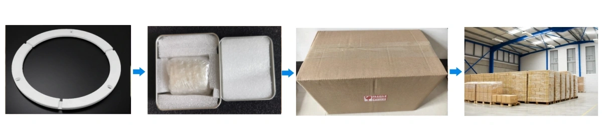
High Purity Alumina Edge Ring Packaging
- Clean protection: each ring is wrapped to prevent surface abrasion and edge impact during transit.
- Rigid isolation: foam/partitioned inner support keeps rings from contacting each other.