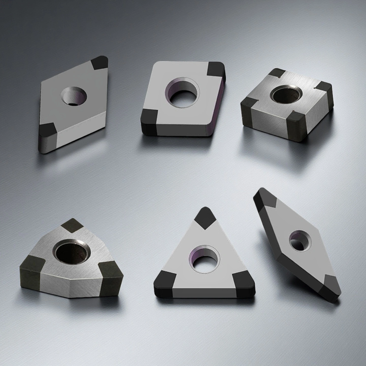
PCBN cutting tools are made from polycrystalline cubic boron nitride, a superhard material designed for high-speed precision machining of hardened steels, cast irons, and powder metallurgy components. With exceptional hardness (45–55 GPa), high thermal stability up to 1200 °C, and chemical inertness against ferrous alloys, PCBN tools deliver extended tool life and superior dimensional accuracy in dry or hard-turning applications.
PCBN Cutting Tools Benefits
- High-Temperature Strength – Maintains stable cutting performance up to 1200 °C, ensuring edge integrity under high-speed, dry machining of HRC 50–70 materials.
- Chemical Inertness – Non-reactive with Fe, Co, Ni, preventing diffusion wear and built-up edge formation in ferrous alloy machining.
- Extended Tool Life – Provides 5–10× longer life than carbide inserts, reducing tool change frequency and improving overall process efficiency.
- Dimensional Accuracy – Edge and chamfer tolerance within ±0.02 mm, achieving IT6–IT7 precision in continuous or interrupted cutting.
- Superior Surface Finish – Delivers Ra ≤ 0.4 µm on hardened steels and chilled cast iron, with wiper-edge geometry enabling higher feed rates.
- Thermal Conductivity & Stability – Conductivity of 60–120 W/m·K ensures uniform heat dissipation and prevents thermal cracking during dry or MQL machining.
Polycrystalline Cubic Boron Nitride (PCBN) Cutting Tools Technical Properties
| Property | Typical Value Range | Unit / Description |
|---|---|---|
| Crystal Structure | Cubic | Polycrystalline microstructure |
| Density | 3.43 – 3.48 | g/cm³ |
| Vickers Hardness (HV) | 45 – 55 | GPa (second only to diamond) |
| Compressive Strength | 4.5 – 6.5 | GPa |
| Flexural Strength | 0.8 – 1.2 | GPa |
| Fracture Toughness (K₁c) | 5 – 7 | MPa·m¹ᐟ² |
| Thermal Conductivity | 60 – 130 | W/m·K (anisotropic; grade-dependent) |
| Thermal Expansion Coefficient | 4.5 – 5.5 ×10⁻⁶ | K⁻¹ (RT–1000 °C) |
| Thermal Stability (Air) | Up to 1200 | °C (oxidation threshold) |
| Electrical Resistivity | 10⁶ – 10⁸ | Ω·cm |
| Elastic Modulus (Young’s Modulus) | 750 – 900 | GPa |
| Poisson’s Ratio | 0.15 – 0.20 | — |
| Chemical Stability | Inert to Fe, Co, Ni; reactive to Al at >1000 °C | — |
| CBN Content (by volume) | 45 % – 95 % | Adjusted for toughness or wear resistance |
| Working Temperature (inert/vacuum) | ≤ 1200 | °C (continuous cutting) |
| Typical Tool Life (hard turning) | 3 – 10× longer than carbide | — |
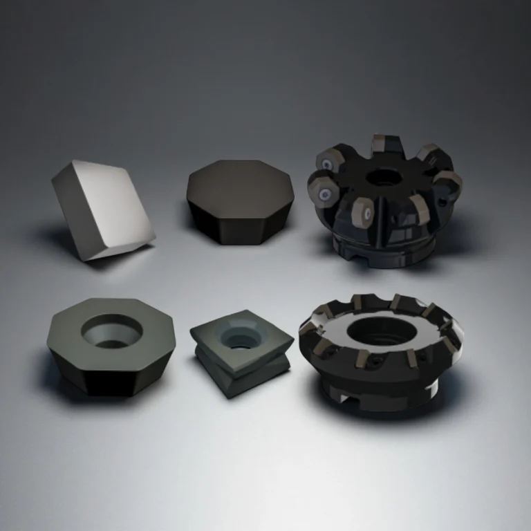
PCBN Cutting Tools Specifications
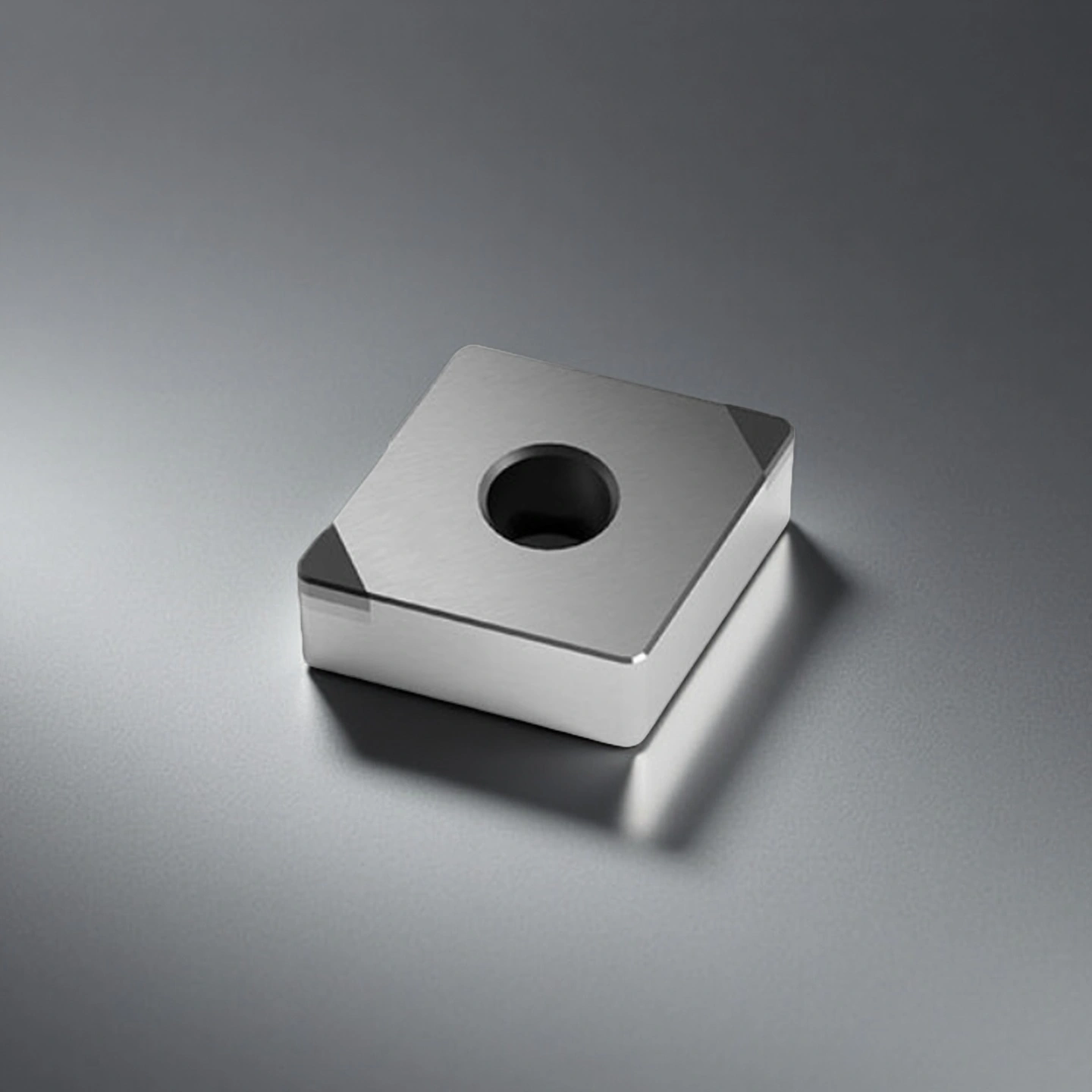
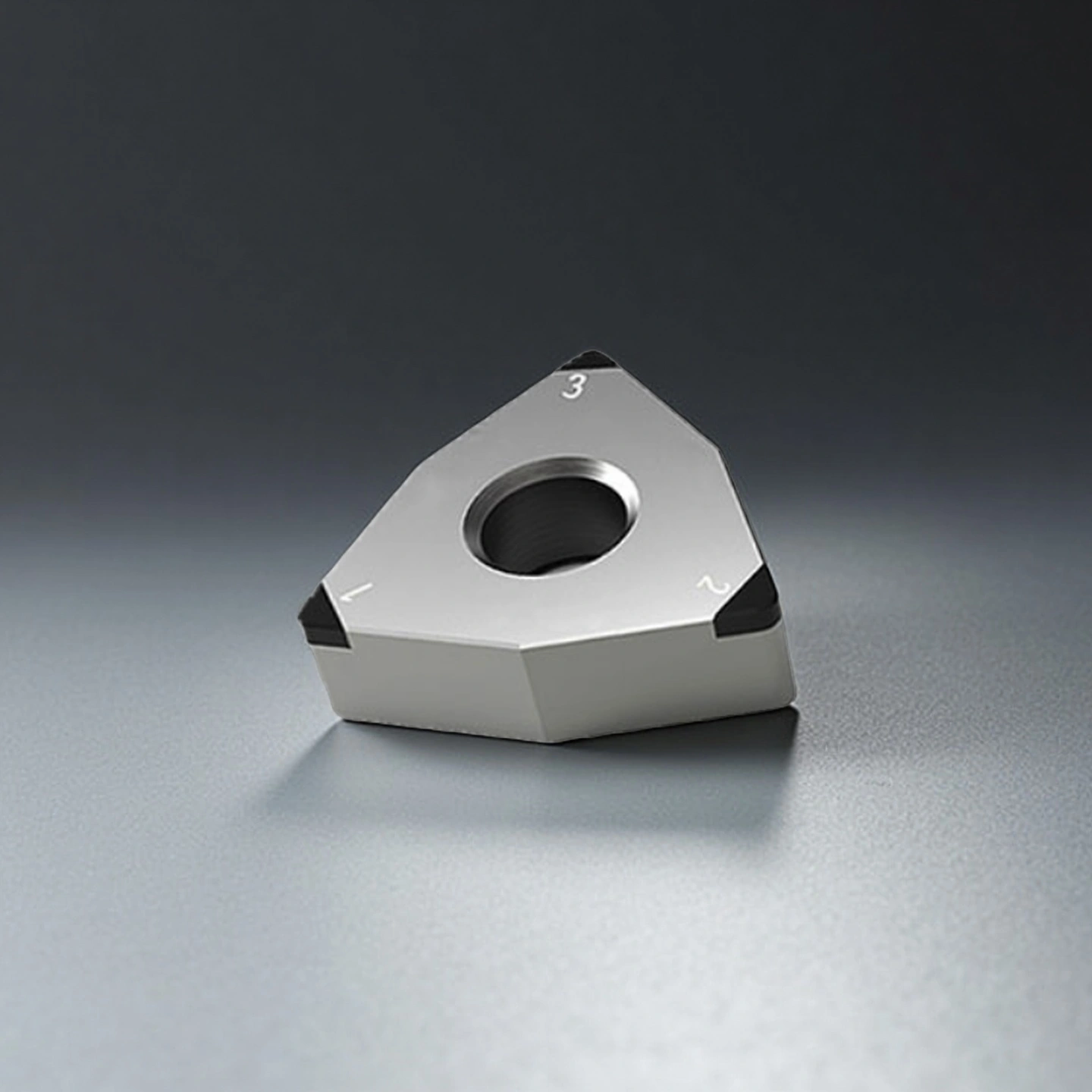
Type 1: PCBN Integral Welding Cutting Tool
| PCBN Integral Welding Cutting Tool | ||||||
| Item NO. | ISO Standard Designation | Cutting Edge Length(mm) | Inner Cutting Circle Dia.(mm) | Thickness(mm) | Bore Diameter(mm) | Radius of Cutting Edge Arc(mm) |
| AT-CNGA120402-4N | CNGA120402-4N | 12 | 12.7 | 4.76 | 5.15 | 0.2 |
| AT-CNGA120404-4N | CNGA120404-4N | 12 | 12.7 | 4.76 | 5.15 | 0.4 |
| AT-CNGA120408-4N | CNGA120408-4N | 12 | 12.7 | 4.76 | 5.15 | 0.8 |
| AT-CNGA120412-4N | CNGA120412-4N | 12 | 12.7 | 4.76 | 5.15 | 1.2 |
| AT-DNGA110402-4N | DNGA110402-4N | 11 | 9.525 | 4.76 | 3.81 | 0.2 |
| AT-DNGA110404-4N | DNGA110404-4N | 11 | 9.525 | 4.76 | 3.81 | 0.4 |
| AT-DNGA110408-4N | DNGA110408-4N | 11 | 9.525 | 4.76 | 3.81 | 0.8 |
| AT-DNGA150402-4N | DNGA150402-4N | 15 | 12.7 | 4.76 | 5.16 | 0.2 |
| AT-DNGA150404-4N | DNGA150404-4N | 15 | 12.7 | 4.76 | 5.16 | 0.4 |
| AT-DNGA150408-4N | DNGA150408-4N | 15 | 12.7 | 4.76 | 5.16 | 0.8 |
| AT-DNGA150412-4N | DNGA150412-4N | 15 | 12.7 | 4.76 | 5.16 | 1.2 |
| AT-SNGA120402-8N | SNGA120402-8N | 12 | 12.7 | 4.76 | 5.16 | 0.2 |
| AT-SNGA120404-8N | SNGA120404-8N | 12 | 12.7 | 4.76 | 5.16 | 0.4 |
| AT-SNGA120408-8N | SNGA120408-8N | 12 | 12.7 | 4.76 | 5.16 | 0.8 |
| AT-SNGA120412-8N | SNGA120412-8N | 12 | 12.7 | 4.76 | 5.16 | 1.2 |
| AT-TNGA160404-6N | TNGA160404-6N | 16 | 9.525 | 4.76 | 3.81 | 0.4 |
| AT-TNGA160408-6N | TNGA160408-6N | 16 | 9.525 | 4.76 | 3.81 | 0.8 |
| AT-TNGA160412-6N | TNGA160412-6N | 16 | 9.525 | 4.76 | 3.81 | 1.2 |
| AT-TNGA220404-6N | TNGA220404-6N | 22 | 12.7 | 4.76 | 5.16 | 0.4 |
| AT-TNGA220408-6N | TNGA220408-6N | 22 | 12.7 | 4.76 | 5.16 | 0.8 |
| AT-TNGA220412-6N | TNGA220412-6N | 22 | 12.7 | 4.76 | 5.16 | 1.2 |
| AT-VNGA160402-4N | VNGA160402-4N | 16 | 9.525 | 4.76 | 3.81 | 0.2 |
| AT-VNGA160404-4N | VNGA160404-4N | 16 | 9.525 | 4.76 | 3.81 | 0.4 |
| AT-VNGA160408-4N | VNGA160408-4N | 16 | 9.525 | 4.76 | 3.81 | 0.8 |
| AT-VNGA160412-4N | VNGA160412-4N | 16 | 9.525 | 4.76 | 3.81 | 1.2 |
| AT-WNGA060402-6N | WNGA060402-6N | 6 | 9.525 | 4.76 | 3.81 | 0.4 |
| AT-WNGA060404-6N | WNGA060404-6N | 6 | 9.525 | 4.76 | 3.81 | 0.8 |
| AT-WNGA060408-6N | WNGA060408-6N | 6 | 9.525 | 4.76 | 3.81 | 0.2 |
| AT-WNGA080402-6N | WNGA080402-6N | 8 | 12.7 | 4.76 | 5.16 | 0.2 |
| AT-WNGA080404-6N | WNGA080404-6N | 8 | 12.7 | 4.76 | 5.16 | 0.4 |
| AT-WNGA080408-6N | WNGA080408-6N | 8 | 12.7 | 4.76 | 5.16 | 0.8 |
| AT-WNGA080412-6N | WNGA080412-6N | 8 | 12.7 | 4.76 | 5.16 | 1.2 |
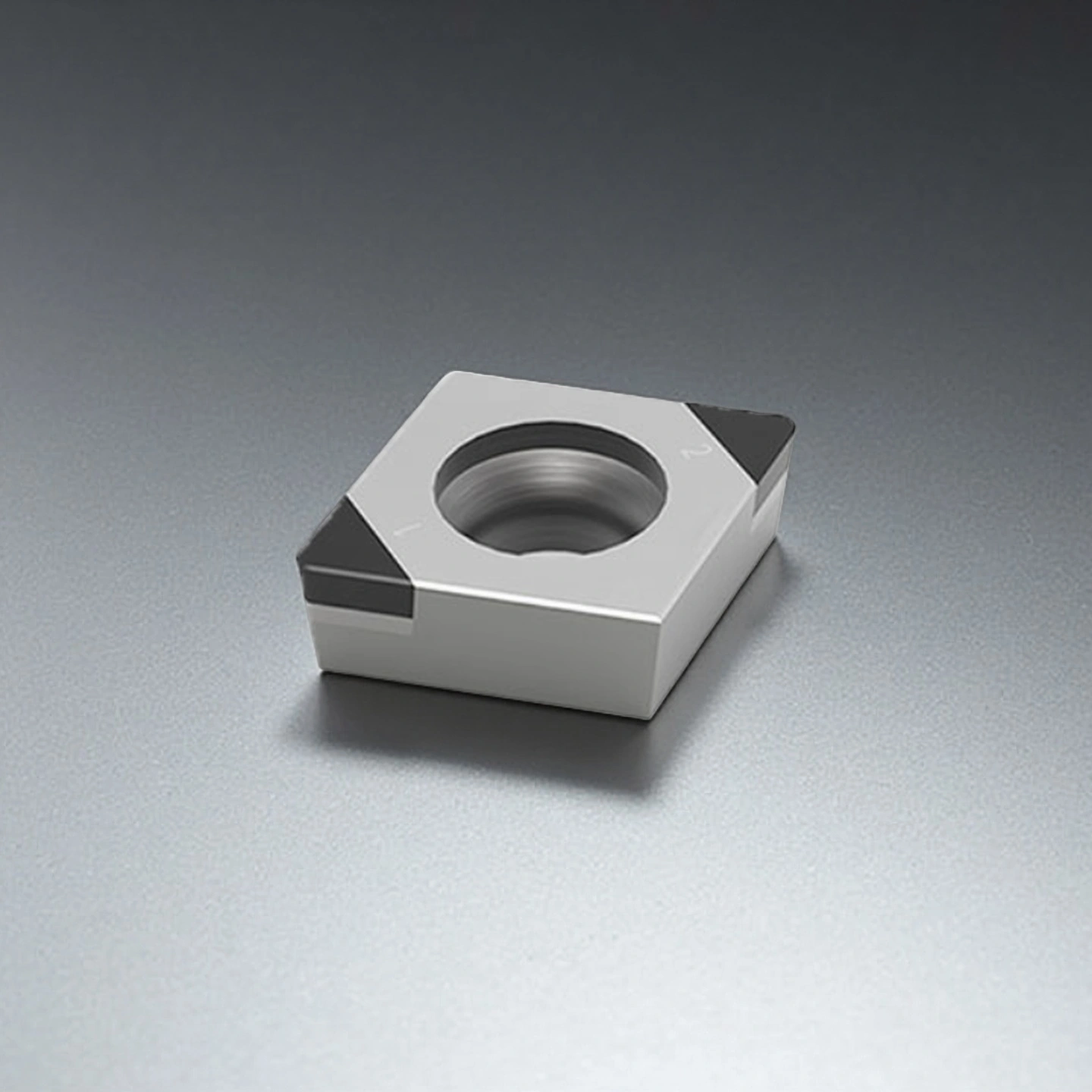
Type 2: PCBN Integral Composite Blades
| PCBN Integral Composite Blades | ||||||
| Item NO. | ISO Standard Designation | Cutting Edge Length(mm) | Inner Cutting Circle Dia.(mm) | Thickness(mm) | Bore Diameter(mm) | Radius of Cutting Edge Arc(mm) |
| AT-CCGW09T302-2N | CCGW09T302-2N | 9 | 9.525 | 3.97 | 4.4 | 0.2 |
| AT-CCGW09T304-2N | CCGW09T304-2N | 9 | 9.525 | 3.97 | 4.4 | 0.4 |
| AT-CCGW09T308-2N | CCGW09T308-2N | 9 | 9.525 | 3.97 | 4.4 | 0.8 |
| AT-CCGW09T312-2N | CCGW09T312-2N | 9 | 9.525 | 3.97 | 4.4 | 1.2 |
| AT-CCGW120402-2N | CCGW120402-2N | 12 | 12.7 | 4.76 | 5.5 | 0.2 |
| AT-CCGW120404-2N | CCGW120404-2N | 12 | 12.7 | 4.76 | 5.5 | 0.4 |
| AT-CCGW120408-2N | CCGW120408-2N | 12 | 12.7 | 4.76 | 5.5 | 0.8 |
| AT-CCGW120412-2N | CCGW120412-2N | 12 | 12.7 | 4.76 | 5.5 | 1.2 |
| AT-CNGA120402-2N | CNGA120402-2N | 12 | 12.7 | 4.76 | 5.15 | 0.2 |
| AT-CNGA120404-2N | CNGA120404-2N | 12 | 12.7 | 4.76 | 5.15 | 0.4 |
| AT-CNGA120408-2N | CNGA120408-2N | 12 | 12.7 | 4.76 | 5.15 | 0.8 |
| AT-CNGA120412-2N | CNGA120412-2N | 12 | 12.7 | 4.76 | 5.15 | 1.2 |
| AT-DCGW070202-2N | DCGW070202-2N | 7 | 6.35 | 2.38 | 2.8 | 0.2 |
| AT-DCGW070204-2N | DCGW070204-2N | 7 | 6.35 | 2.38 | 2.8 | 0.4 |
| AT-DCGW070208-2N | DCGW070208-2N | 7 | 6.35 | 2.38 | 2.8 | 0.8 |
| AT-DCGW11T302-2N | DCGW11T302-2N | 11 | 9.525 | 3.97 | 4.4 | 0.2 |
| AT-DCGW11T304-2N | DCGW11T304-2N | 11 | 9.525 | 3.97 | 4.4 | 0.4 |
| AT-DCGW11T308-2N | DCGW11T308-2N | 11 | 9.525 | 3.97 | 4.4 | 0.8 |
| AT-TCGW0902 | TCGW0902 | 9.6 | 5.56 | 2.38 | 2.5 | 0.2 |
| AT-TCGW1103 | TCGW1103 | 11 | 6. 35 | 3.18 | 2.8 | 0.2 |
| AT-TCGW16T302-3N | TCGW16T302-3N | 16 | 9.525 | 3.97 | 4.4 | 0.2 |
| AT-TNGA160404-3N | TNGA160404-3N | 16 | 9.525 | 4.76 | 3.81 | 0.4 |
| AT-TNGA160408-3N | TNGA160408-3N | 16 | 9.525 | 4.76 | 3.81 | 0.8 |
| AT-TNGA160412-3N | TNGA160412-3N | 16 | 9.525 | 4.76 | 3.81 | 1.2 |
| AT-TNGA220404-3N | TNGA220404-3N | 22 | 12.7 | 4.76 | 5.16 | 0.4 |
| AT-TNGA220408-3N | TNGA220408-3N | 22 | 12.7 | 4.76 | 5.16 | 0.8 |
| AT-TNGA220412-3N | TNGA220412-3N | 22 | 12.7 | 4.76 | 5.16 | 1.2 |
| AT-WNGA060402-3N | WNGA060402-3N | 6 | 9.525 | 4.76 | 3.81 | 0.2 |
| AT-WNGA060404-3N | WNGA060404-3N | 6 | 9.525 | 4.76 | 3.81 | 0.4 |
| AT-WNGA060408-3N | WNGA060408-3N | 6 | 9.525 | 4.76 | 3.81 | 0.8 |
| AT-WNGA080402-3N | WNGA080402-3N | 8 | 12.7 | 4.76 | 5.16 | 0.2 |
| AT-WNGA080404-3N | WNGA080404-3N | 8 | 12.7 | 4.76 | 5.16 | 0.4 |
| AT-WNGA080408-3N | WNGA080408-3N | 8 | 12.7 | 4.76 | 5.16 | 0.8 |
| AT-WNGA080412-3N | WNGA080412-3N | 8 | 12.7 | 4.76 | 5.16 | 1.2 |
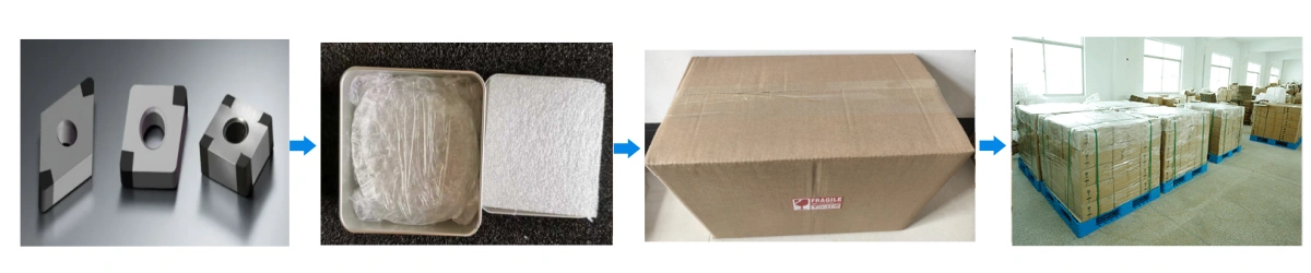
PCBN Cutting Tools Packaging
- Each insert is individually packed in anti-static plastic boxes with foam protection.