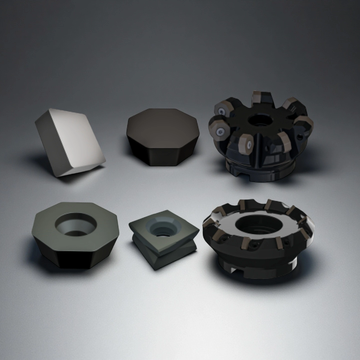
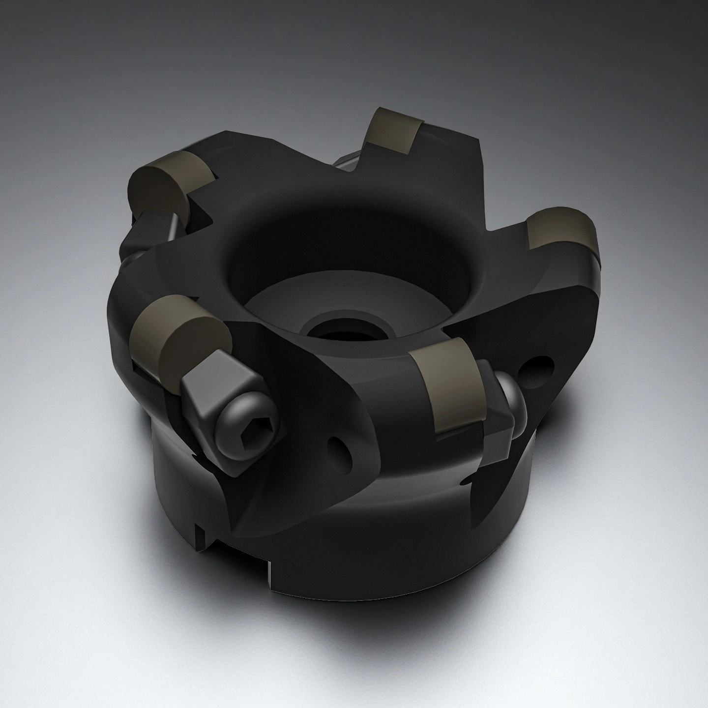
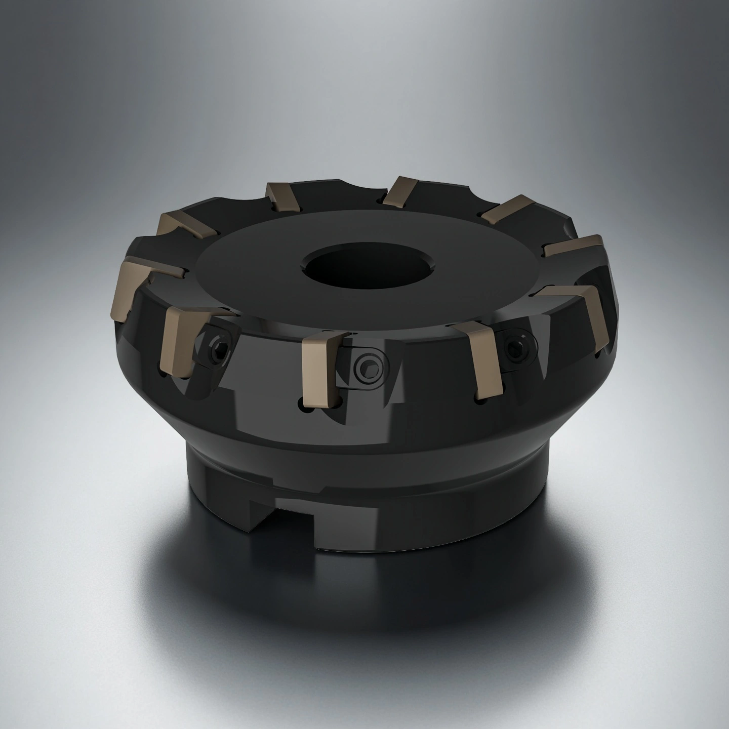
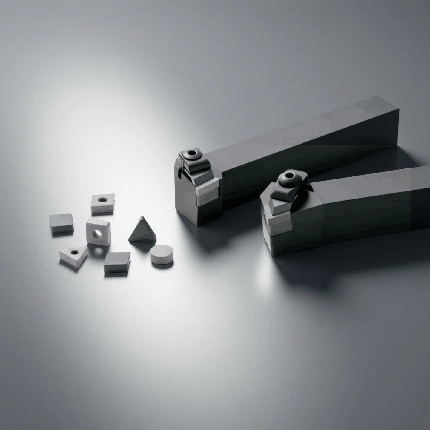
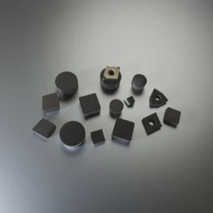
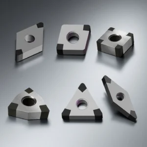
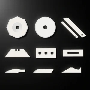
Silicon Nitride Cutting Tools are machining tools whose working edges are made from sintered silicon nitride (Si₃N₄) ceramics. They are engineered for high-speed, dry or MQL cutting where hot hardness, thermal-shock resistance and chemical stability are critical.
Silicon Nitride Cutting Tools Benefits
- High surface-speed capability: Stable performance in cast iron cutting at typical Vc 600–1200 m/min (application-dependent, trial required), even under dry machining, thanks to Si₃N₄ hot hardness and thermal stability.
- Low adhesion to iron phases: The chemical inertness of Si₃N₄ minimizes diffusion and adhesion to ferrous alloys, effectively reducing built-up edge and crater wear. This ensures smoother chip evacuation, lower friction and stable cutting forces during prolonged roughing cycles.
- Tunable edge preparation: Customizable T-land, honed or micro-chamfered edges allow precise control over thermal shock and notch wear behavior. Edge preparation can be optimized for heavy interrupted cutting and fine finishing operations.
- Thickness and flatness control: Manufactured with dimensional tolerances of ±0.025–0.05 mm, supporting balanced tool geometry and minimal runout. This precision helps maintain consistent workpiece engagement, cutting stability and repeatability in automated systems.
- SiAlON option for HRSA machining: The SiAlON composite grade (Si₃N₄–Al₂O₃ solid solution) provides improved resistance to thermal shock and oxidation compared with standard silicon nitride. It is particularly effective for roughing nickel-based superalloys and Inconel under dry or semi-dry conditions.
Silicon Nitride Cutting Tools Properties
|
Si3N4 Type |
Gas pressure sintering Si3N4 |
Hot pressing sintering Si3N4 |
High thermal conductivity Si3N4 |
|
Density (g/cm3) |
3.2 |
3.3 |
3.25 |
|
Flexural Strength (MPa) |
700 |
900 |
600~800 |
|
Young Modulus (GPa) |
300 |
300 |
300~320 |
|
Poisson's ratio |
0.25 |
0.28 |
0.25 |
|
Compressive strength (MPa) |
2500 |
3000 |
2500 |
|
Hardness (GPa) |
15 |
16 |
15 |
|
Fracture toughness (MPa*m1/2) |
5~7 |
6~8 |
6~7 |
|
Maximum working temperature (℃) |
1100 |
1300 |
1100 |
|
Thermal conductivity (W/m*K) |
20 |
25 |
80~100 |
|
Thermal expansion coefficient (/℃) |
3*10-6 |
3.1*10-6 |
3*10-6 |
|
Thermal shock resistance (ΔT ℃) |
550 |
800 |
/ |
|
Tolerance: |
|
1. Diameter Tolerance: ±0.003mm |
|
2. Hole Depth: ±0.005mm |
|
3. Surfance Roughness:Ra0.02 |
|
4. Cylindricity:±0.003mm |
|
5. Concentricity:±0.002mm |
|
6. Parallelism: ±0.002mm |
Si₃N₄ Cutting Tools Specifications
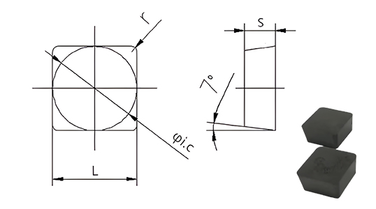
Type 1: Silicon Nitride 7° Square Blade with Relief Angle
|
Type 1: Silicon Nitride 7° Square Blade with Relief Angle |
|
Item NO. |
L - Cutting Edge Length(mm) |
i.c. - Inscribed Circle Diameter(mm) |
S - Thickness(mm) |
|
AT-SIN-SCGN0903 |
9.525 |
9.525 |
3.18 |
|
AT-SIN-SCGN0904 |
9.525 |
9.525 |
4.76 |
|
AT-SIN-SCGN1204 |
12.7 |
12.7 |
4.76 |
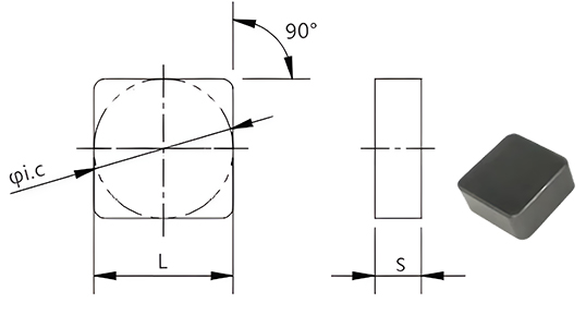
Type 2: Silicon Nitride Square CNC Cylindrical Turning Blade
|
Type 2: Silicon Nitride Square CNC Cylindrical Turning Blade |
|
Item NO. |
L - Cutting Edge Length(mm) |
i.c. - Inscribed Circle Diameter(mm) |
S - Thickness(mm) |
|
AT-SIN-SCGN0904 |
9.525 |
9.525 |
4.76 |
|
AT-SIN-SCGN1204 |
12.7 |
12.7 |
4.76 |
|
AT-SIN-SCGN1207 |
12.7 |
12.7 |
7.94 |
|
AT-SIN-SCGN1608 |
16.0 |
16.0 |
8.0 |
|
AT-SIN-SCGN2010 |
20.0 |
20.0 |
10.0 |
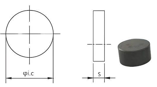
Type 3: Silicon Nitride Round Blade
|
Type 3: Silicon Nitride Round Blade |
|
Item NO. |
i.c. - Inscribed Circle Diameter(mm) |
S - Thickness(mm) |
|
AT-SIN-RNGN0604 |
6.35 |
4.76 |
|
AT-SIN-RNGN0904 |
9.525 |
4.76 |
|
AT-SIN-RNGN1204 |
12.7 |
4.76 |
|
AT-SIN-RNGN1207 |
12.7 |
7.94 |
|
AT-SIN-RNGN1608 |
16.0 |
8.0 |
|
AT-SIN-RNGN2008 |
20 |
8 |
|
AT-SIN-RNGN2010 |
20.0 |
10.0 |
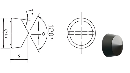
Type 4: Silicon Nitride Conical Hole Cutter Blade
|
Type 4: Silicon Nitride Conical Hole Cutter Blade |
|
Item NO. |
i.c. - Inscribed Circle Diameter(mm) |
S - Thickness(mm) |
|
AT-SIN-RCGX0605 |
6.35 |
5.0 |
|
AT-SIN-RCGX0907 |
9.525 |
7.94 |
|
AT-SIN-RCGX1207 |
12.7 |
7.94 |
|
AT-SIN-RCGX1510 |
15.875 |
10.0 |
|
AT-SIN-RCGX1910 |
19.05 |
10.0 |
|
AT-SIN-RCGX2010 |
20 |
10.0 |
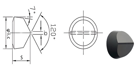
Type 5: Silicon Nitride V-Shaped Hole Cutter Blade
|
Type 5: Silicon Nitride V-shaped Hole Cutter Blade |
|
Item NO. |
i.c. - Inscribed Circle Diameter(mm) |
S - Thickness(mm) |
|
AT-SIN-RCGV0604 |
6.35 |
4.76 |
|
AT-SIN-RCGV0907 |
9.525 |
7.94 |
|
AT-SIN-RCGV1207 |
12.7 |
7.94 |
|
AT-SIN-RCGV1510 |
15.875 |
10.0 |
|
AT-SIN-RCGV1910 |
19.05 |
10.0 |
|
AT-SIN-RCGV2012 |
20.0 |
12.0 |
|
AT-SIN-RCGV2512 |
25.0 |
12.0 |
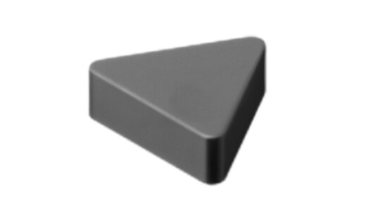
Type 6: Silicon Nitride Triangle Blade
|
Type 6: Silicon Nitride Triangle Blade |
|
Item NO. |
L - Cutting Edge Length(mm) |
i.c. - Inscribed Circle Diameter(mm) |
S - Thickness(mm) |
|
AT-SIN-TNGN1103 |
11.0 |
6.35 |
3.18 |
|
AT-SIN-TNGN1604 |
16.5 |
9.525 |
4.76 |
|
AT-SIN-TNGN1603 |
16.5 |
9.525 |
3.18 |
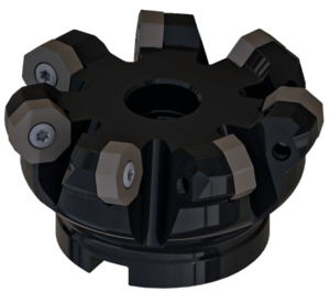
Type 7: Custom Silicon Surface Nitride Milling Cutter
|
Silicon Nitride Surface Milling Cutter 43° |
|
Item No. |
Diameter (mm) |
Thickness (mm) |
Picture |
|
AT-SIN-SK0043 |
Customize |
 |
|
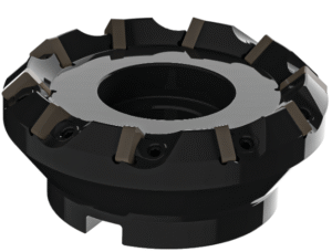
Silicon Nitride Surface Milling Cutter 45° |
|
Item No. |
Diameter (mm) |
Thickness (mm) |
Picture |
|
AT-SIN-SK0045 |
Customize |
 |
|
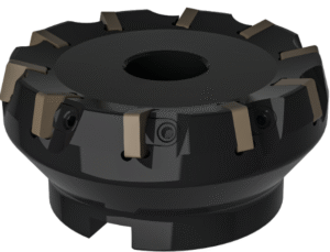
Silicon Nitride Surface Milling Cutter 75° |
|
Item No. |
Diameter (mm) |
Thickness (mm) |
Picture |
|
AT-SIN-SK0075 |
Customize |
 |
|
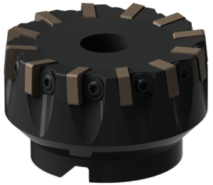
Silicon Nitride Surface Milling Cutter 88° |
|
Item No. |
Diameter (mm) |
Thickness (mm) |
Picture |
|
AT-SIN-SK0088 |
Customize |
 |
|
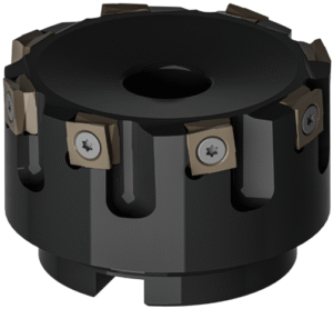
Silicon Nitride Milling Cutter 90° |
|
AT-SIN-SK0090 |
Customize |
 |
|
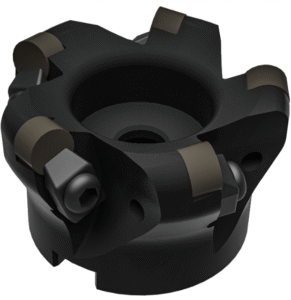
Silicon Nitride Square Milling Cutter |
|
AT-SIN-SK0001 |
Customize |
 |
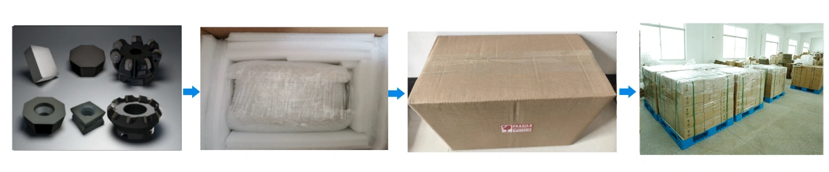
Si₃N₄ Ceramic Inserts Packaging
- Each tool is individually packed in anti-static, shock-absorbing foam boxes.
Silicon Nitride Cutting Tools Applications
ADCERAX Si₃N₄ ceramic inserts are developed for high-speed machining of grey cast iron, ductile iron and compacted graphite iron. Their combination of hot hardness, thermal-shock resistance and edge strength makes them suitable for rigid, stable machining conditions where conventional cutting tools may experience rapid wear at higher cutting speeds.
From automotive components to heavy castings, ADCERAX supports standard ISO insert families and drawing-reviewed configurations. Insert geometry, thickness, corner radius and edge preparation can be evaluated according to the workpiece, operation, toolholder and cutting conditions.
-
Automotive Cast-Iron Components
Typical parts: Brake discs, brake drums, flywheels, wheel hubs and other high-volume cast-iron components.
Typical operations: External turning, facing, roughing and finishing of grey or ductile cast-iron surfaces.
Application challenges: Automotive production often requires consistent cutting across repeated cycles while controlling edge wear, surface condition and interruptions at holes, grooves or casting features.
Why Si₃N₄ fits: Silicon nitride ceramic inserts retain hardness at elevated cutting temperatures and are suitable for high-speed dry machining. Round and square insert geometries can distribute cutting loads while maintaining edge strength during continuous or lightly interrupted cuts.
ADCERAX advantage: We can review the ISO insert family, corner radius and edge preparation according to the component geometry and machining stage. This provides a more application-focused insert configuration for roughing, semi-finishing or finishing operations.
-
Cast Housings and Heavy Machinery Components
Typical parts: Pump housings, gearbox cases, valve bodies, bearing housings and general machinery castings.
Typical operations: Rough turning, facing, bore machining and finishing of cast surfaces, shoulders and interrupted features.
Application challenges: Heavy castings may include casting skin, sand inclusions, uneven hardness or variable engagement. These conditions can increase the risk of edge chipping, vibration and unstable wear.
Why Si₃N₄ fits: The fracture resistance and thermal stability of silicon nitride make it suitable for demanding cast-iron machining where both cutting speed and edge reliability must be considered.
ADCERAX advantage: Insert thickness, support geometry, edge form and corner radius can be reviewed against the toolholder and workpiece features. T-land, honed and chamfered edge options can be considered for different levels of interruption and cutting load.
-
Engine and Powertrain Castings
Typical parts: Cylinder blocks, cylinder liners, bearing caps, exhaust components and compacted graphite iron parts.
Typical operations: High-speed turning, facing and finishing of grey, ductile or compacted graphite iron components.
Application challenges: Engine and powertrain parts may combine long continuous cuts with holes, shoulders and changing engagement. Compacted graphite iron can also place higher mechanical loads on the cutting edge than conventional grey iron.
Why Si₃N₄ fits: GPSN and HPSN silicon nitride routes can be considered for different combinations of hardness, interruption and machine rigidity. The final insert configuration should balance edge strength, cutting stability and the required surface condition.
ADCERAX advantage: ADCERAX supports round, square, triangular and clamping-hole insert families, together with drawing-reviewed dimensions and configurable edge preparation. This allows the insert to be evaluated around the actual machining operation instead of relying on one standard geometry for every cast-iron component.
-
Foundry and General Cast-Iron Machining
Typical parts: Flanges, pulleys, rolls, sleeves, industrial fittings and other grey or ductile iron components.
Typical operations: Removal of casting skin, diameter turning, facing, profiling and preparation of functional surfaces.
Application challenges: Foundry parts can vary in hardness, surface scale, material allowance and interruption. A cutting insert that performs well on one casting may need a different edge form or corner radius for another component.
Why Si₃N₄ fits: Silicon nitride ceramic inserts provide a practical route for increasing cutting speed in suitable cast-iron operations while maintaining resistance to heat and mechanical loading.
ADCERAX advantage: Standard ISO geometries and custom configurations can be reviewed for different casting sizes, machining allowances and toolholder systems. Trial support helps identify a suitable starting configuration before moving into regular production.
Si3N4 Ceramic Cutting Tools Usage Instructions
Correct installation, rigid toolholding and controlled cutting conditions are essential for stable performance from silicon nitride (Si₃N₄) cutting tools. The following guidelines cover installation, operation, wear monitoring, maintenance and handling for cast-iron machining.
-
Installation Guidelines
1. Pocket cleanliness and seating: Clean the insert pocket and remove chips, oil and burrs before installation. Debris beneath the insert can cause uneven seating, vibration and edge damage.
2. Insert matching: Confirm that the insert geometry, thickness and clamping features match the toolholder specification.
3. Toolholder inspection: Check the pocket, shim, clamp and screw for wear or deformation before installing the insert.
4. Clamping torque: Tighten the insert according to the toolholder manufacturer’s torque recommendation. Insufficient or excessive clamping can damage the insert or affect cutting stability.
5. Seating and runout: Verify that the insert is fully seated and that runout is acceptable for the machine, toolholder and operation.
-
Operation Parameters
The following are typical starting parameters and are application-dependent; verify on your machine and workpiece by trial.
1. Stable grey or ductile cast-iron machining:
a. Cutting speed (Vc): Typical starting reference of 600–900 m/min
b. Feed rate (f): Set according to the insert geometry, corner radius and surface requirement
c. Depth of cut (ap): Set according to the stock allowance, edge length and machine rigidity
d. Environment: Dry machining with consistent chip evacuation is generally preferred
2. Harder or interrupted cast-iron machining: Begin below the stable cutting-speed reference. A 15–25% speed reduction may be used as an initial trial reference.
3. Coolant consideration: If MQL or coolant is used, maintain a consistent supply. Avoid intermittent coolant contact with a hot ceramic edge because rapid temperature changes may cause thermal cracking.
4. Trial adjustment: Change only one parameter at a time and record the cutting conditions, edge condition and workpiece surface after each adjustment.
-
Tool Wear Monitoring
1. Initial inspection: Inspect the insert during setup trials and after each parameter adjustment.
2. Wear condition: Monitor flank wear, notch wear, micro-chipping, thermal cracks and changes in the workpiece surface.
3. Replacement point: Define the replacement point according to the application, edge condition and workpiece requirements instead of using one universal wear limit.
4. Stop condition: Stop machining if severe chipping, cracking, vibration or unstable wear occurs.
-
Maintenance & Handling
1. Post-operation cooling: Allow hot inserts to cool naturally. Do not quench them or apply coolant directly after machining.
2. Cleaning and storage: Clean inserts carefully and store them in protective trays or their original packaging.
3. Edge protection: Prevent ceramic cutting edges from contacting other inserts, tools or hard surfaces.
4. Toolholder maintenance: Inspect the pocket and clamping components before installing a new insert.
5. Reconditioning: Review the remaining edge condition and original geometry before considering regrinding.