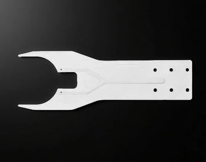
Custom Ceramic Arms and End Effectors for Precision Handling
Custom ceramic forks, blades and contact parts for wafer handling, carriers and precision workpieces.
ADCERAX is a China-based advanced ceramics manufacturer specializing in custom ceramic arms, handling forks, gripper fingers and vacuum end effectors for industrial automation. Their heat resistance, electrical insulation and wear resistance help protect workpieces, maintain stable positioning and extend service life.
Our engineers work directly with production, giving equipment builders a simpler path from initial design to repeat orders.
Choose a complete arm or replaceable ceramic contact tips.
Alumina, ZTA, Si3N4 and SiC considered by actual duty.
Small-batch validation before repeat purchasing.
Critical datums and acceptance points defined before production.
Solution families
Find the Ceramic Handling Solution That Matches Your Task
Compare the working outline, contact locations and mounting interface together. A ceramic end effector is the contact or support part at the robot interface; covers, pads and gripping hardware define the assembly around it.
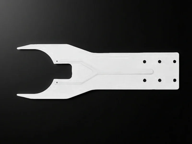
- Contact task
- Support around an open center while leaving clearance below the workpiece.
- Interface features
- Mounting-hole pattern; open fork head.
- Match to the drawing
- Opening width, contact position, reach and mounting-hole spacing.
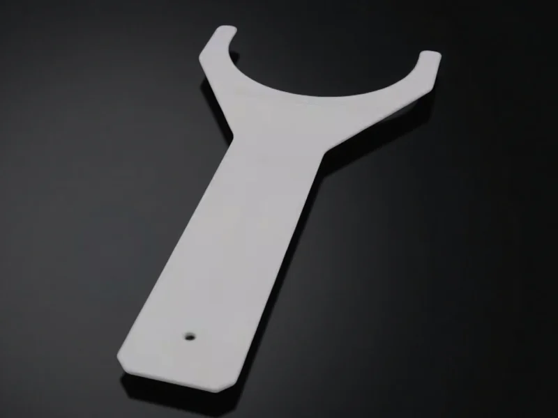
- Contact task
- Place support around a round or shaped workpiece.
- Interface features
- Curved opening; long shank; end mounting hole.
- Match to the drawing
- Opening profile, support height, shank position and entry clearance.
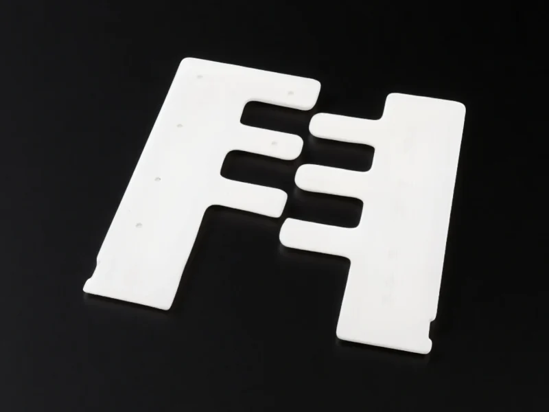
- Contact task
- Distribute support across a wider workpiece-contact layout.
- Interface features
- Open slots and small face holes.
- Match to the drawing
- Slot width, contact plane, working width and port arrangement.
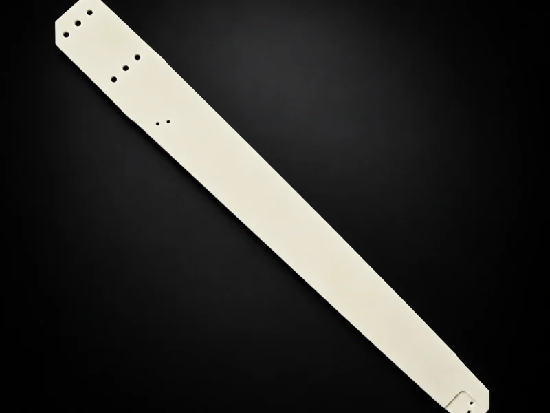
Narrow blades & fingers
- Contact task
- Bring a slender support profile into a restricted handling space.
- Interface features
- Long, solid blade profile with a group of small holes at one end.
- Match to the drawing
- Working thickness, unsupported reach, contact width and hole spacing.
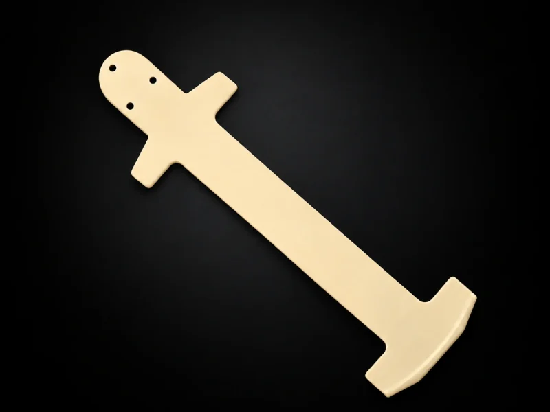
- Contact task
- Place support across a wider end span than the central arm.
- Interface features
- Transverse end features extend beyond the central arm profile.
- Match to the drawing
- End span, contact height, mounting interface and fixture clearance.
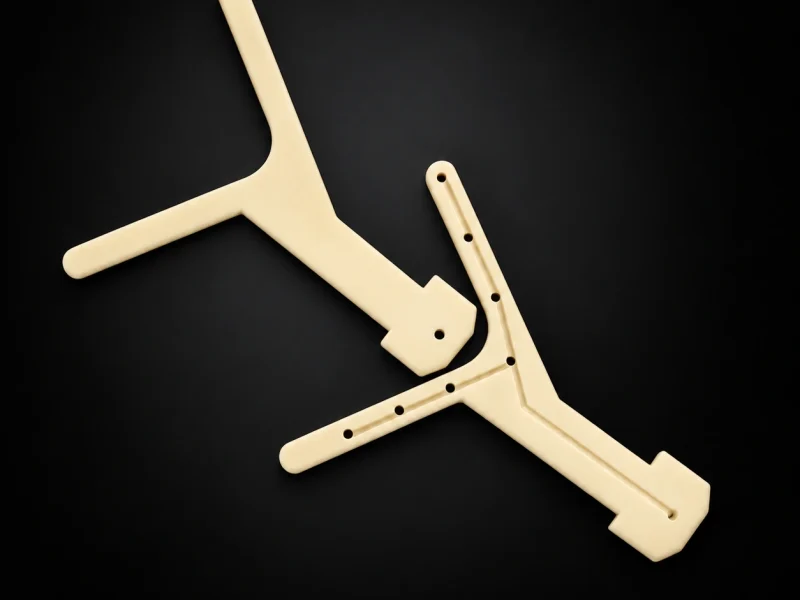
Y-shaped forks & grooved faces
- Contact task
- Branched outlines provide separated arm sections around an open center.
- Interface features
- Y-shaped outlines; one form has visible face grooves and small holes.
- Match to the drawing
- Branch span, surface-groove layout, hole positions and permitted contact zones.
Application fit
Ceramic end effectors for wafer-handling projects
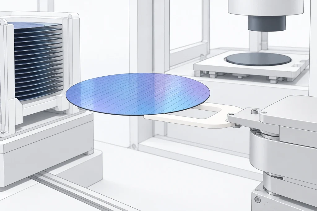
For wafer transfer, sorting and inspection, first decide where the workpiece may be touched. That choice sets the support positions, entry clearance and holding arrangement.
- Backside support
Place ceramic wafer forks or pads under permitted support areas; keep forbidden zones clear.
- Edge-only contact
- Define the edge profile, contact points and clearance to the wafer face.
- Transfer & inspection
- Match thickness and reach to the cassette, fixture or measurement position.
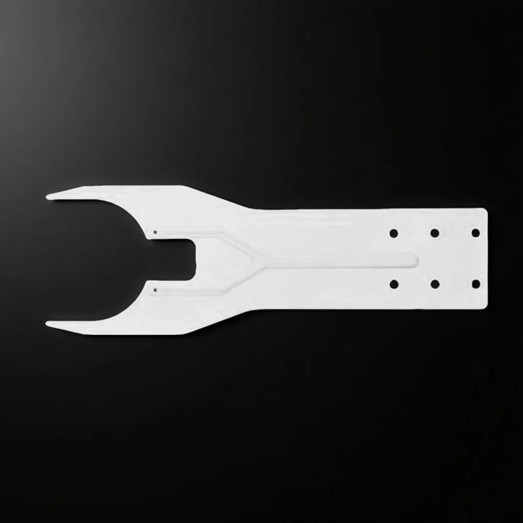
Fork geometry
Compare the opening, support position and equipment interface.
Glass, thin sheets & carriers
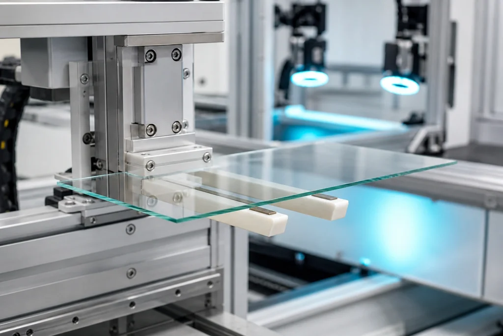
Glass and thin sheets make support span, warpage and contact-pad choice especially relevant. For a tray or carrier, align the support positions with its mass, center of gravity and approach path.
Vacuum and heated positions
Use the arm's actual location, temperature and pressure conditions. A transfer component outside the process zone has a different duty from a process-exposed part; pads, seals and bonding materials belong in the same review.
Identify existing equipment
Identify the robot, then define the ceramic end effector
Use the equipment model and installed end-effector details to define the part you need. Record the robot, wrist or holder, and finger separately. ADCERAX manufactures drawing-defined ceramic contact and support parts for the specified interface and operating conditions.
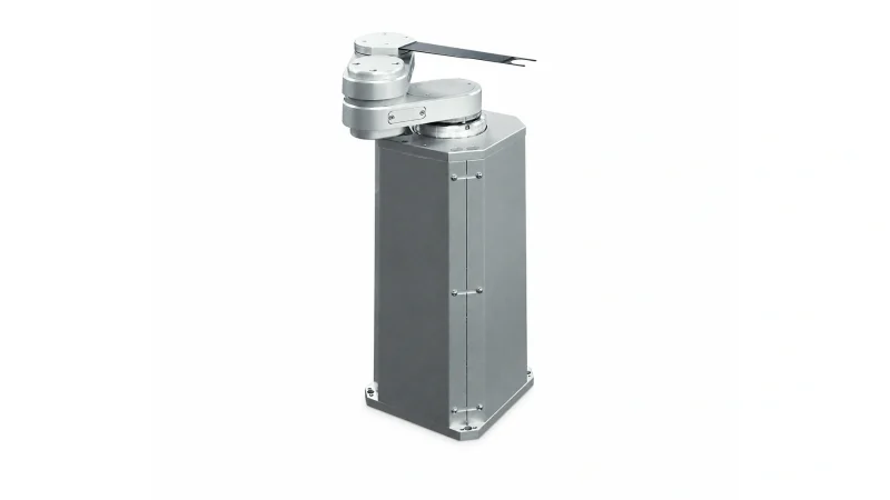
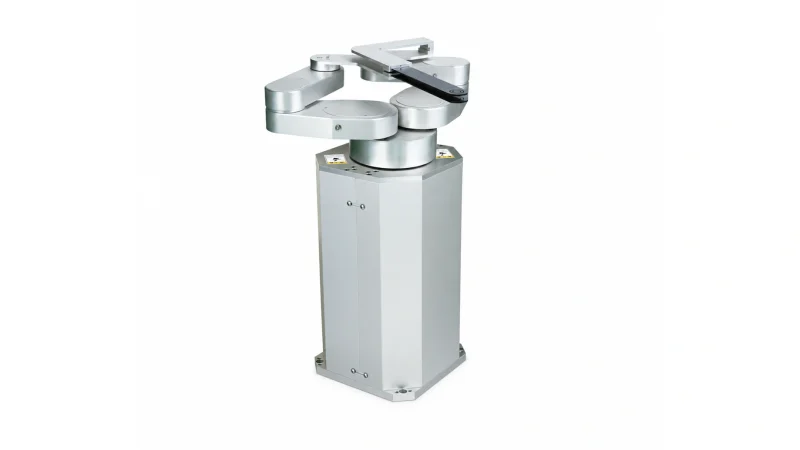
JEL SCR3100S series
Compact single-arm wafer handling in atmospheric cleanroom equipment. The SCR3100S-200-PM standard example handles wafers up to 150 mm.
- End-effector check
- Check the installed wrist and finger numbers, mounting datum and pickup method.
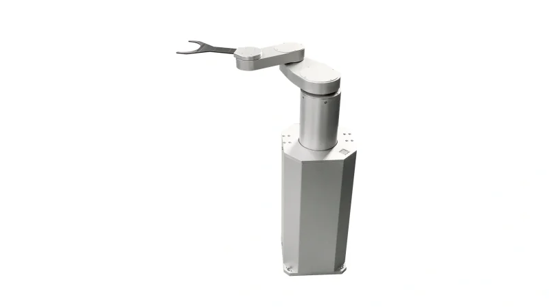
JEL STCR4160S series
Twin-arm wafer handling in atmospheric cleanroom equipment. The STCR4160S-300-PM standard example handles wafers up to 300 mm.
- End-effector check
Check upper and lower finger positions, spacing, wrist number and vacuum routing.
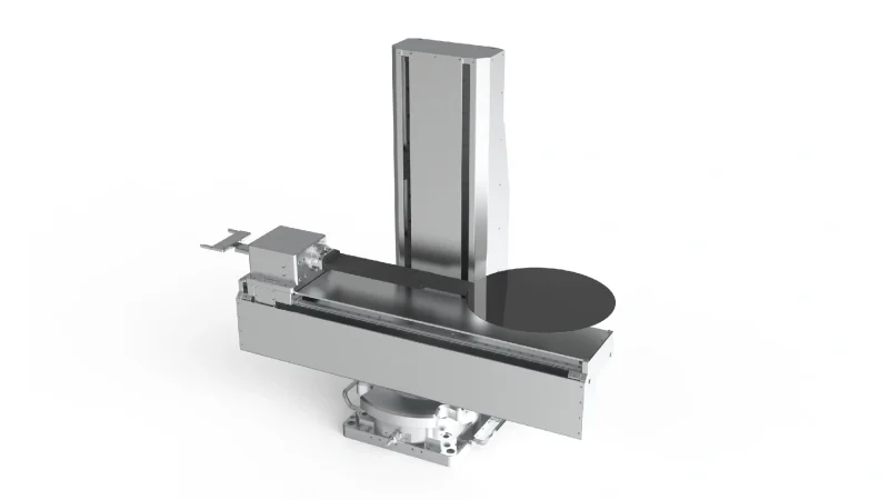
SRT Rb100 series
Wafer transfer for substrates up to 300 mm, with vacuum, passive support, edge-grip and Bernoulli holding options.
End-effector check
Identify the installed holding method, wrist interface and wafer-contact pattern.
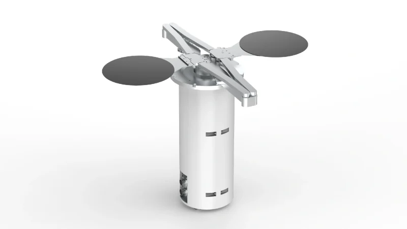
XIVI ROBOT LTR
Linear wafer transfer for 300 mm wafers. Its published configuration specifies an alumina ceramic fork, vacuum pickup and a fork thickness of up to 2.5 mm.
End-effector check
Check fork thickness, mounting geometry, vacuum port and transfer clearance.
XIVI ROBOT ZTR
Dual-arm substrate transfer in vacuum chambers, with published wafer sizes of 6, 8, 10 and 12 inches.
End-effector check
Check chamber conditions, end-effector interface and transfer clearance.
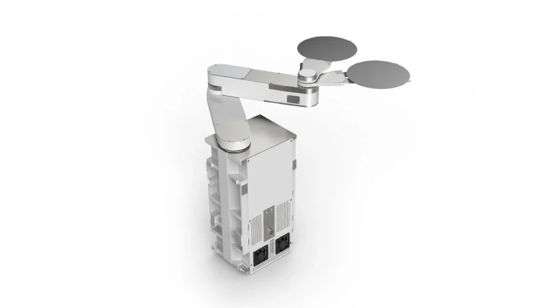
XIVI ROBOT STR dual-end-effector series
Wafer handling with two independently controlled arms for EFEM loading.
End-effector check
Check upper and lower end-effector spacing, orientation and motion clearance.
Identify existing equipment
Identify your existing ceramic arm
An original part number and equipment model help identify the design for a replacement review. Record the part or finger identifier separately from the robot, wrist or holder, then confirm the drawing revision and interface.
The original specifications below describe JEL vacuum fingers in high-purity alumina with a conductive Teflon coating. Compare the full finger model, wafer range and wrist option. ADCERAX evaluates a custom part against your drawing, wrist interface and acceptance requirements.
| JEL FINGER MODEL | ORIGINAL FORM & WAFER SIZE | ORIGINAL OVERALL LENGTH × THICKNESS (MM) | SCR3100S WRIST OPTIONS |
|---|---|---|---|
| SC-IW-200 | I-shaped; 3-inch and 100–200 mm wafers | 200 × 2 | SARS00169 / SARS02659 / SARS08603 |
| SC-YW-200 | Y-shaped; 100–200 mm wafers | 200 × 2 | SARS00169 / SARS02659 / SARS08603 |
| 3D-02229 | Y-shaped; 150–300 mm wafers | 242 × 2 | SARS00169 / SARS02659 / SARS08603 |
| SC3-YW-240 | Y-shaped; 300 mm wafers | 240 × 3 | SARS00958 / SARS02967 |
| 3D-01661 | Y-shaped; 300 mm wafers | 242 × 3 | SARS00958 / SARS02967 |
240 mm / 242 mm
Different length references
Overall length is separate from wafer diameter and unsupported reach. Compare the mounting datum, effective reach and motion clearance when reviewing these two finger lengths.
2 mm / 3 mm
Separate thickness checks
Match the original thickness against the mounting stack, contact height and available clearance. A similar outline or the same wafer size does not establish interchangeability.
01 Replacing an existing part
Record four identities separately: equipment model, wrist or holder module, ceramic finger part number and drawing revision. Add front, back, interface and port photographs where drawings are incomplete.
Resolve first
handedness, hole pattern, locating features, contact height, air ports and included accessories.
02 Developing a new design
Begin with the workpiece, permitted contact zones and available motion envelope. Then define the ceramic shape and the connection to the robot or holder.
Resolve first
contact layout, reach, section thickness, material route and supplied-part boundary.
03 Qualifying a second source
Freeze the drawing, material, assembly contents and acceptance plan before comparing samples or quotations.
Resolve first
critical dimensions, functional checks, documentation, change control and approval responsibility.
Choose the material route
Material Options for Your Custom Ceramic Arm
Consider 99.5%, 99.7% and 99.9% alumina, dense 3Y zirconia, structural silicon nitride and the two distinct SiC routes. Select the grade around the geometry and contact environment, rather than choosing on purity alone.
| MATERIAL ROUTE | DENSITY (g/cm³) | WHAT IT HELPS YOU COMPARE |
|---|---|---|
|
High-purity alumina 99.5% / 99.7% / 99.9% Al₂O₃ |
3.94 99.7% grade; typical |
A starting point for rigid, electrically insulating support parts. Compare the specified grade and contact-finish requirements; higher purity alone does not establish cleaner contact or ESD behavior. |
| Dense 3Y-TZP zirconia |
6.00–6.08 typical |
Consider fracture toughness together with the higher ceramic-body mass of the same geometry. Specify 3Y; other stabilizer systems and ESD formulations are separate materials. |
|
Structural silicon nitride Si₃N₄ |
3.2 typical |
A structural material route for comparing component mass, strength and fracture toughness. Use structural-grade data, rather than thin-substrate values. |
|
Reaction-bonded SiC RBSC / SiSiC |
≥3.02 Material data-sheet limit |
Contains residual silicon. Specify this route separately from pressureless-sintered SiC when considering the environment, cleaning exposure and manufacturing route. |
|
Pressureless-sintered SiC SSiC |
3.10 Typical |
Has no silicon-infiltrated phase. Compare its stiffness and ceramic-body mass for the proposed geometry; dense SSiC and a porous contact pad serve different roles. |
These are grade-specific material selection data. Part mass also depends on geometry and the supplied components; density alone does not set the arm’s load capacity. The material and manufacturing route are agreed for the selected configuration.
Need a Ceramic Arm That Fits Your Equipment?
Send your drawing or old-part photos with the workpiece, temperature, handling method and mounting interface. We’ll review the material, geometry and critical contact surfaces before quoting.
01 / What can be customized
Custom Ceramic Arms Built Around Your Handling Task
A ceramic arm must fit both the equipment and the workpiece it handles. Define the features below around your installation, contact conditions and purchase scope.
01
Arm form
Forks, blades, paddles, gripper fingers and replaceable contact pieces. Define the outline around the workpiece and available handling space.
02
Material route
Alumina, zirconia, silicon nitride and SiC. For an existing ZTA or other special-material part, provide the grade or material record.
03
Geometry & dimensions
Overall length, reach, width, thickness, fork opening, tine profile, steps, chamfers and edge radii.
04
Mounting interface
Hole patterns, slots, counterbores, locating features and metal-holder interfaces, referenced to the installation datums.
05
Contact areas & finish
Support locations, contact profiles, permitted contact zones, flatness, roughness and the finish on working surfaces.
06
Suction layout & assembly
Suction-hole locations, grooves, ports, covers, seals and connectors. Define the holding method and which components are included.
The manufacturing route and any sealed or internal passages are confirmed from the proposed geometry and assembly. A suction layout does not by itself establish suitability for use inside a vacuum chamber.
02 / Define custom geometry & fit
Define the dimensions that fit your equipment
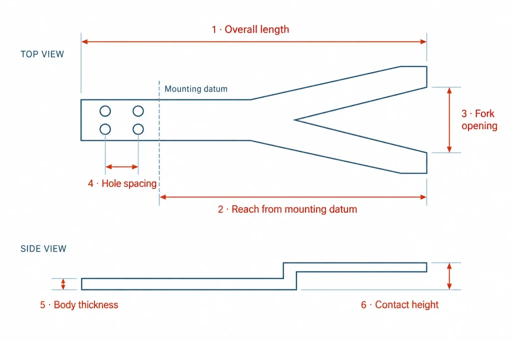
- Overall length describes the complete ceramic part. Reach starts at the mounting datum, so it tells you how far the working end extends into the machine.
- Fork opening and hole spacing locate the working area and attachment. Thickness and contact height determine vertical clearance and the support plane.
- For a replacement, compare these fields with the original revision and the wrist or holder interface. Include handedness and no-contact zones where they affect fit.
Read the interface beside the part
The drawing fixes the dimensions for the selected configuration.
03 / Define contact, holding & supply scope
Shape, gripping method and assembly are separate choices
A fork outline does not identify its holding method. Compare the contact route and supplied components separately to make like-for-like choices.
Passive support
The workpiece rests on defined support locations. Motion, orientation and contact geometry determine retention.
Vacuum-assisted holding
Contact openings connect to a gripping circuit. Pads, seals and the air path affect the assembled function.
Porous contact pads
A porous pad is a separate contact element from the dense ceramic body; visible holes do not prove porosity.
Edge grip / contact inserts
The ceramic contact piece works with a holder or gripping mechanism.
| Ceramic body | Drawing revision, material grade and contact features. |
| Cover / bonding | Cover material, sealing or bonding method and any no-adhesive requirement. |
| Contact pads / seals | Material, contact position, attachment and included replacement pieces. |
| Hardware / finish | Fasteners, connectors and surface treatments; who supplies and verifies each item. |
Vacuum gripping
Vacuum gripping depends on the pressure difference between the suction side and the surrounding environment.
Vacuum-chamber service
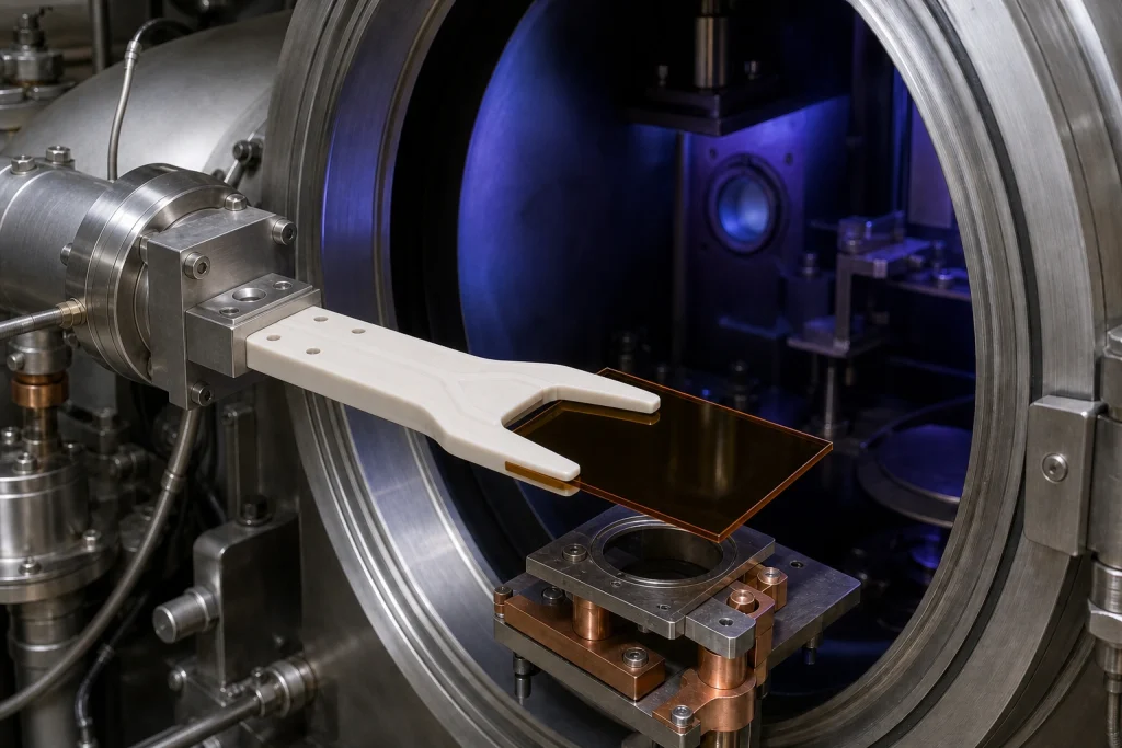
Vacuum-chamber service adds requirements for chamber pressure, outgassing, seals, cleaning and temperature.
Specify both operating pressures, with units, and the complete flow path.
A cover-sealed air path and a one-piece internal channel are different constructions; define the required route before comparing assemblies.
From Concept to Repeat Order
The process is organized around the decisions your project requires, from application screening to repeat production.
Confirm the handling task, workpiece, failure mode and operating environment.
Align the material, structure, interfaces, critical surfaces, inspection plan and lead time.
Build a small batch for fit, handling, thermal or vacuum trials in your equipment.
Carry the approved drawing, inspection points and packaging into repeat production.
Why ADCERAX
Custom Ceramic Arm Engineering and Production Support
- Engineering Support: Drawings, samples, materials and key interfaces reviewed before production.
- Flexible Production: From prototypes and small batches to repeat orders.
- Multi-Material Supply: Alumina, ZTA, zirconia, silicon nitride and silicon carbide.
- Precision Inspection: Key dimensions, datums, mounting features and contact surfaces checked before shipment.
- Repeat-Order Control: Approved drawings and inspection points retained for future batches.
- Export Support: Protective packaging, documents and international shipping.
ADCERAX coordinates engineering review, ceramic processing, precision finishing, inspection and export delivery through one supply chain—reducing handoffs from prototype to repeat production.
Frequently Asked Questions About Ceramic Arms
Should I use a full ceramic arm or ceramic tips on a metal holder?
Use a full ceramic arm when continuous insulation, clean contact and stable geometry are needed and impact is controlled. A hybrid holder is often better when the tool sees collision risk, high fastening loads or frequent maintenance because the ceramic contact pieces can be replaced separately.
Is high-purity or black ceramic automatically ESD safe?
No. Purity, color and electrical insulation do not establish electrostatic dissipation. Insulating ceramic, a bulk-dissipative formulation and a conductive or dissipative surface treatment are different routes. Define the required electrical behavior, bulk or surface resistance, contact pads, grounding path and test conditions for the assembled component before selecting a grade.
Can internal vacuum channels and custom suction holes be produced?
They can be reviewed from the drawing. Feasibility depends on wall thickness, channel path, port design, sealing method, machining access and the required holding or leakage test. The vacuum source and workpiece surface should be provided with the RFQ.
Can ADCERAX make a replacement from an old part?
Yes, an old part can be used as an engineering reference. For a dependable replacement, we still need mounting datums, key dimensions, functional surfaces, material information and operating conditions. A fit test is recommended before repeat purchasing.
What tolerances and surface finish should I specify?
Specify only the dimensions and surfaces that affect installation or function. Identify mounting datums, hole position, flatness or parallelism over a stated length, and roughness on the true contact area. Achievable values are confirmed after material, size and machining access are reviewed.
How can I troubleshoot common ceramic arm problems?
Check mounting torque, corner geometry and support spacing for breakage; vacuum sealing and hole distribution for unstable holding; and contact pressure and surface finish for scratches. For replacement-fit issues, verify mounting dimensions against the latest drawing.
Is a ceramic arm a complete robot or gripper?
A ceramic arm or end effector is the component that supports, contacts or holds the workpiece at the robot interface. The ceramic body may be supplied separately from covers, contact pads, seals, connectors and actuators. Define the required parts in the bill of materials.
Can an existing equipment part number identify a replacement?
An original part number narrows the design to review. For example, JEL SC-IW-200 identifies an I-shaped finger, while SC-YW-200 identifies a Y-shaped finger. In that reference table, SCR3100S is the robot model and the SARS identifiers are wrist options. Record your equipment model, fitted wrist or holder, and drawing revision separately. Compare the original length, thickness, mounting interface, contact geometry and supplied components. ADCERAX evaluates the custom part against the actual drawing and acceptance requirements; the original reference does not establish interchangeability.
Does vacuum gripping mean the arm is suitable for a vacuum chamber?
No. Vacuum gripping describes how a pressure difference holds the workpiece. Operation inside a vacuum chamber also depends on the pressure environment, outgassing, seals, adhesives, materials and cleaning requirements. Specify both the gripping circuit and the surrounding environment.
How should internal vacuum channels be specified?
Show the ports, channels, contact openings, cover or sealing arrangement and any no-adhesive requirement on the drawing. The construction route, supplied components and agreed leak or gripping tests are reviewed for that design. Monolithic internal channels cannot be assumed from a photograph or from the presence of surface grooves.
Which ceramic material should be selected?
Start with the contact task, geometry, moving mass, electrical requirement and environment. Compare 99.5%, 99.7% or 99.9% alumina by grade, dense 3Y-TZP zirconia, structural silicon nitride, reaction-bonded SiC and pressureless-sintered SiC. The density table helps compare ceramic-body mass at the same volume; finished-part and assembly acceptance remain separate.
Which ceramic arm configuration should I choose?
Choose a one-piece ceramic arm for continuous ceramic contact and insulation, a metal holder with replaceable ceramic fingers for easier maintenance, or a vacuum arm for suction-based handling. Match the configuration to your workpiece, mounting loads and operating conditions.
Request a Ceramic Arm Engineering Review
Share the project details you have, with a drawing or old-part photos where available.
- Drawing & Project: Drawings or reference photos, project type and any current issue.
- Workpiece & Interface: Workpiece dimensions and weight, holding method and mounting details.
- Operating Conditions: Temperature, atmosphere and any special requirements.
- Quantity & Delivery: Sample quantity, expected repeat demand and required delivery date.
ADCERAX will review the material, structure, critical dimensions, inspection requirements and prototype route before providing a quotation and expected lead time. Replacement projects may require a sample or fit check before the design is approved.
*Our team will answer your inquiries within 24 hours.
*Your information will be kept strictly confidential.
info@adcerax.com
Tel:+86-0731-84428843
WhatsApp:+86 19311583352
Within 24 hours