A specification-grade discussion of why alumina tubes that "survive" 1500–1700°C in catalog terms can still fail in continuous service, and how grain size, boundary chemistry, porosity, and support geometry combine to govern shape retention. Written for materials and process engineers who need to convert microstructural understanding into a defensible RFQ rather than a temperature label. The article separates creep from thermal shock and span-induced bending, identifies the procurement variables worth controlling, and ends with the supplier-evidence package that distinguishes design-grade alumina tubes from catalog-grade ones.
For alumina tubes used above 1500°C, creep resistance generally improves when the microstructure is dense, impurity-controlled, and not excessively fine, because very fine grains add grain-boundary area and accelerate diffusion-assisted deformation. Grain size is not the only lever — residual porosity, boundary glassy phases, dopant chemistry, tube geometry, support span, and applied load can dominate whether a tube that survives peak temperature still holds shape in continuous service. The correct specification question is therefore microstructure under service condition, not temperature rating alone.
Continuous service above 1500°C exposes alumina tubes to time-dependent deformation that no peak-temperature rating alone can predict.
What Creep Looks Like in Alumina Tubes Above 1500°C
Above approximately 1500°C, an alumina tube can remain chemically intact and still become mechanically unreliable because the limiting issue shifts from temperature tolerance to time-dependent deformation under load. Engineers see this as gradual bowing, loss of straightness, wall distortion, dimensional drift, or contact between the tube and nearby fixtures after extended hold times — particularly in horizontal layouts or wherever the tube carries sample weight or sealing hardware.
Continuous service temperature is not the same as peak withstand temperature. A tube can hold the furnace setpoint and still fail the application when shape retention matters. This distinction is where most upstream selection mistakes originate: catalog ratings describe survival, not function.
Above 1500°C, alumina tubes do not usually fail because the temperature is too high. They fail because the duty cycle assumed temperature was the only variable.
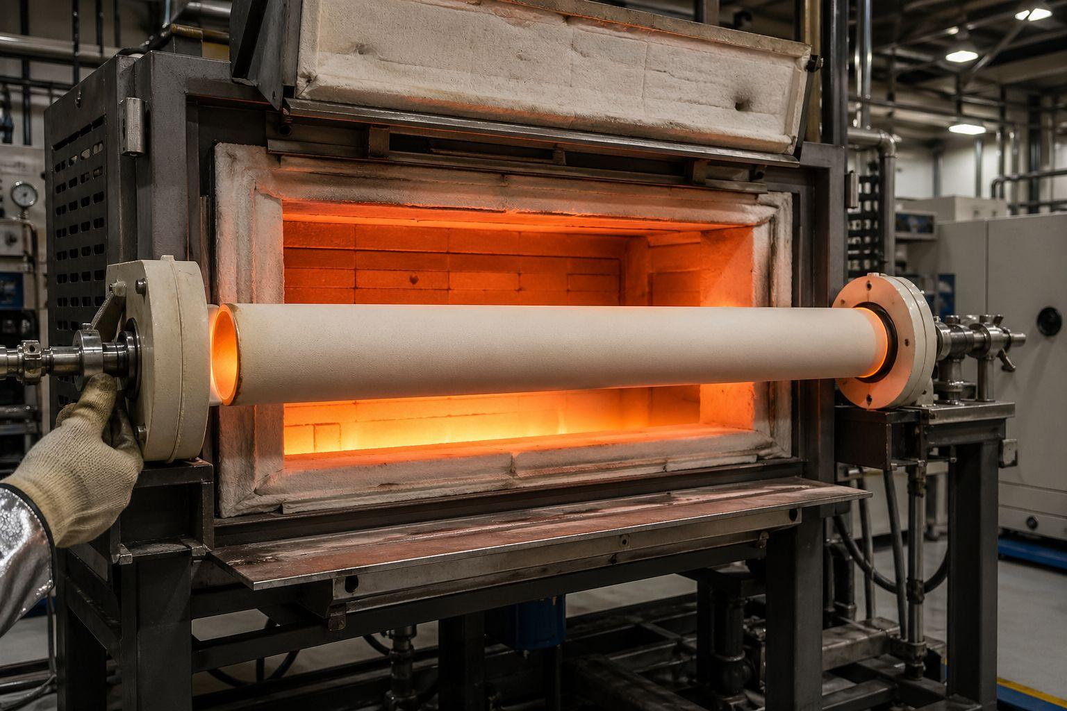
A typical scenario engineers in laboratory furnace and heat-treatment equipment design encounter is the horizontal protection sheath: nominally rated for 1700°C peak, specified at 99% purity, and visibly straight on installation. After several hundred hours of holds in the 1550–1650°C band with sample-side loading, the tube develops a measurable mid-span sag. The temperature label was correct. The service envelope was not.
Continuous Service Temperature vs Peak Withstand Temperature
Peak temperature describes what the material survives without immediate fracture or melting. Continuous service temperature describes what it tolerates over hours or thousands of hours without losing the property the application depends on — usually shape retention, mechanical strength, or chemical integrity. For tubes carrying load or spanning distance, the latter governs.
Why Horizontal Tubes Fail Sooner Than the Temperature Label Suggests
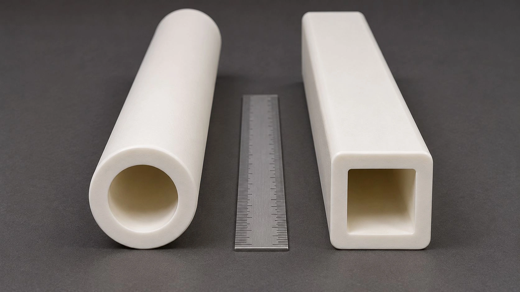
Horizontal orientation converts the tube's own weight, plus any attached fixtures or samples, into a steady bending stress at high temperature. Combined with long hold times, this drives steady-state creep that vertical or short-span configurations may never see. Wall thickness, outer diameter, and support span enter the calculation before grain size does.
How Grain Size Changes Creep Behavior — and When It Stops Being the Main Lever
Creep in polycrystalline alumina is strongly tied to stress, temperature, and grain size, because the dominant high-temperature deformation routes involve diffusion and grain-boundary processes. Fine-grained alumina tends to be more grain-size sensitive because greater boundary area creates more pathway for diffusion-assisted deformation and grain-boundary sliding. Coarse-grained alumina can move toward regimes where creep becomes less grain-size dependent and more stress-sensitive.
Reviews of alumina creep literature describe fine-grained behavior with grain-size exponents around 2–3, while coarse-grained alumina shows reduced grain-size dependence at higher stresses. Fine-grained 1.2 μm polycrystalline alumina has been reported near 1×10⁻⁴ s⁻¹ at 56 MPa and 1415°C in historical creep data — not as a universal benchmark, but as evidence that fine microstructures can deform measurably below the catalog peak rating.
This is the counterintuitive part. The intuition that "finer grain is always better" comes from room-temperature flexural and hardness data, where fine grains genuinely improve performance. Above 1500°C, the same microstructure can become a liability because grain-boundary diffusion has more interface to work with.
Why Very Fine Grains Can Improve Sinterability but Hurt High-Temperature Shape Retention
Fine starting powders sinter densely at lower temperatures and produce uniform tubes with attractive room-temperature data sheets. The trade-off appears only at service temperature: more boundary area means more diffusion paths, and creep rate increases accordingly. The same tube that looks excellent in incoming inspection can creep faster in continuous service than a coarser-grained alternative with identical purity.
Why Grain-Boundary Chemistry Can Matter as Much as Average Grain Size
Boundary chemistry is the variable most often missing from datasheets. Work on doped alumina has shown that ppm-level segregating dopants — certain rare-earth additions, in particular — can reduce creep rate in 1–2 μm alumina by orders of magnitude relative to undoped equivalents. The implication for procurement is direct: specifying "99.5% Al₂O₃" without addressing boundary phases or sintering-aid chemistry leaves the most influential variable uncontrolled.
A common diagnostic error in high-temperature alumina substitution projects is comparing two tubes by purity and average grain size alone, finding them nominally equivalent, and being unable to explain why one creeps and the other does not. The answer usually lives at the boundaries.
Creep vs Thermal Shock vs Support Error: The Misdiagnosis Section
Not every distorted or cracked alumina tube has a grain-size problem. Creep is time-dependent and geometry-dependent: it grows with hold time, temperature, span, and load, and shows up as gradual loss of straightness or progressive dimensional drift. Thermal shock is linked to rapid temperature gradients and produces cracking, spalling, or abrupt damage after ramping or quenching — not gradual sag. Support error is the third category: a tube too long for its span, too thin for its diameter, or clamped in a way that adds bending stress can mimic poor creep resistance even if the microstructure is fine.
Misdiagnosis is expensive. An engineer who blames the powder will spend a procurement cycle requalifying suppliers when the actual root cause was a 600 mm unsupported horizontal span on a 25 mm OD thin-wall tube.
| Failure Mode | Root Cause | Diagnostic Signature | Prevention Threshold |
|---|---|---|---|
| Creep deformation | Time + temperature + load + microstructure | Gradual bowing, sagging, dimensional drift over hold | Limit hold time at >1500°C; reduce span/load; specify creep-resistant microstructure |
| Thermal shock damage | Rapid gradient on ramp or quench | Abrupt cracks, edge spall, fracture after cycling | Ramp <5°C/min near upper range; verify per ASTM C1525 |
| Support-induced bending | Long unsupported span / poor fixture | Localized bend at mid-span, permanent set | Reduce span; add intermediate support; thicker wall |
| Purity-limited service failure | Boundary glassy/impurity phases mobile at temperature | Faster distortion than peer tubes; contamination | Tighten chemical analysis; control sintering aids |
| Porosity / density weakness | Insufficient densification, open porosity | Lower strength, leakage, earlier distortion | Specify bulk density and open porosity per ASTM C20 / C830 |
Failure modes referenced against ASTM C1211, C1291, C1525, C20/C830, and C577 verification methods; field-observed pattern across high-temperature furnace tube installations.
What Creep Looks Like in Service Records
Service logs that show distortion increasing monotonically with cumulative hours at temperature, without a corresponding ramp-rate excursion, point to creep. Tubes pulled for inspection show smooth bowing rather than sharp damage. The recovery direction — whether reversing the orientation or rotating the tube reduces the apparent sag over subsequent runs — is another diagnostic.
What Signs Point to Thermal Shock Instead
Sharp radial or longitudinal cracks, edge spalling, and damage that appears after a specific quench or ramp event point to thermal shock. The damage is event-correlated, not hour-correlated. ASTM C1525 thermal-shock methodology applies here, not creep verification.
When Geometry/Support Dominates Over Microstructure
If two tubes from different suppliers, both with acceptable purity and density, both fail at the same span and orientation, the variable is the assembly. The fix is mechanical — shorter span, intermediate support, vertical orientation, or thicker wall — not a different powder.
Selection Thresholds: When Alumina Still Works, and What Must Be Specified
The selection rule for this temperature range should not be "use high-purity alumina above 1500°C." It should be a window statement: alumina remains viable when the tube operates in a stable atmosphere with controlled ramp rates, manageable span and load, dense low-porosity microstructure, and a boundary chemistry that does not accelerate grain-boundary transport.
The decision begins to flip when one or more of the following move in the wrong direction: very long unsupported horizontal span, thin-wall geometry, repeated holds near the upper service range, large thermal gradients, vacuum or reducing conditions that tighten purity requirements, or microstructures optimized for easy densification rather than long-term creep resistance. Above 1700°C, even high-purity alumina ceramic grades require careful evaluation against alternative materials.
| Service Condition | Acceptable | Required | Either |
|---|---|---|---|
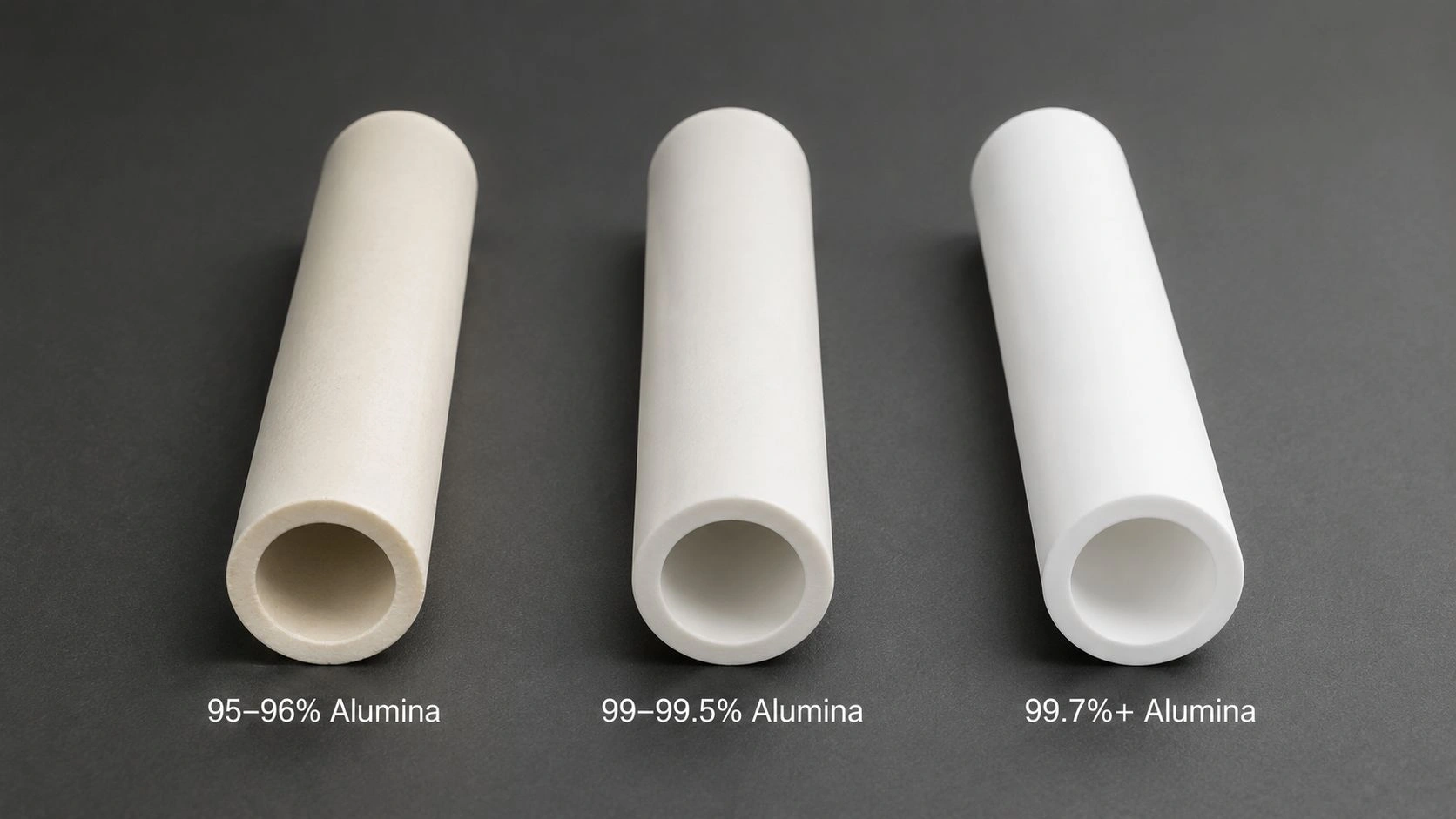
| Stable air, moderate load, controlled ramps <5°C/min | 99% Al₂O₃, controlled grain size 5–25 μm | Bulk density >3.85 g/cm³; open porosity <0.5% | Standard catalog grade if data verified |
| Continuous hold 1550–1700°C with mechanical load | — | 99.7%+ Al₂O₃, dopant disclosure, elevated-temp strength data | Custom microstructure spec |
| Long horizontal unsupported span | — | Geometry redesign or intermediate support; thicker wall | Supplier support recommendation in writing |
| Fast thermal cycling (>10°C/min) | — | Thermal shock data per ASTM C1525 | Consider redesign before microstructure change |
| Vacuum or reducing atmosphere, contamination-sensitive | 99.7%+ purity, certified chemistry | Atmosphere limit statement, outgassing data | Application-specific qualification |
Threshold ranges reflect typical specification practice for high-temperature industrial furnace ceramics; verify against supplier-specific test data per ASTM C1211 elevated-temperature strength and C1291 creep methods.
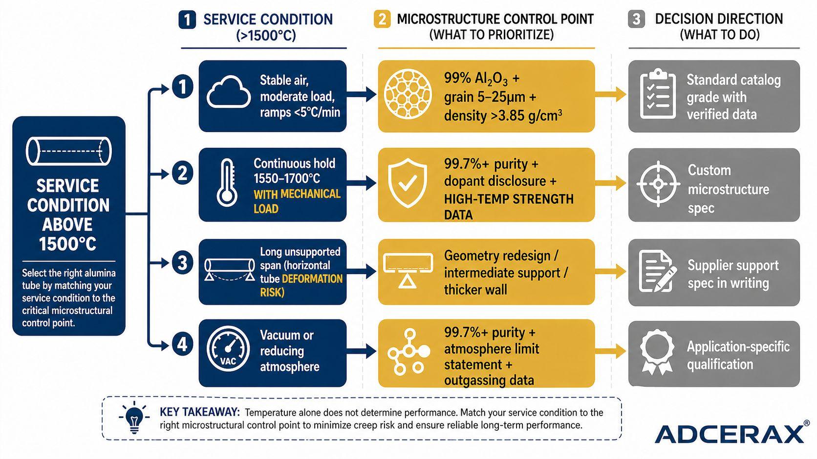
Selection routing maps service condition to the microstructural variable that actually controls outcome — not to the temperature label on the catalog page.
Practical Decision List: Fine-Grained vs Coarser, Denser Alumina
For continuous service above 1500°C with mechanical load: prefer microstructures in the moderate grain-size range with high density and controlled boundary chemistry over very fine-grained alumina, even when both meet the same purity specification. For pulse-style service with rapid cycling and minimal load: thermal shock resistance and wall thickness matter more than grain size selection.
When Purity Matters More Than Grain Size
In vacuum, reducing, or contamination-sensitive atmospheres, impurity volatilization and boundary phase mobility become the limiting factors. Here, 99.7%+ purity with documented chemistry outweighs grain size optimization. Purity controls what gets into the process; grain size controls how the tube holds shape.
When Alumina Should Yield to Another Material or a Redesigned Assembly
Above approximately 1700°C in continuous mechanical-load service, or in vacuum at temperatures where alumina volatilization becomes measurable, the engineering question is no longer "which alumina grade" but "is alumina the right material." Mullite, recrystallized SiC, or zirconia-toughened alumina enter the comparison. Redesigning the assembly to reduce span, eliminate horizontal load, or shorten hold time is often the cheaper path than material change. Browse alumina tube applications for context on where the boundaries of alumina viability typically sit.
What to Ask a Supplier to Prove Before Approval
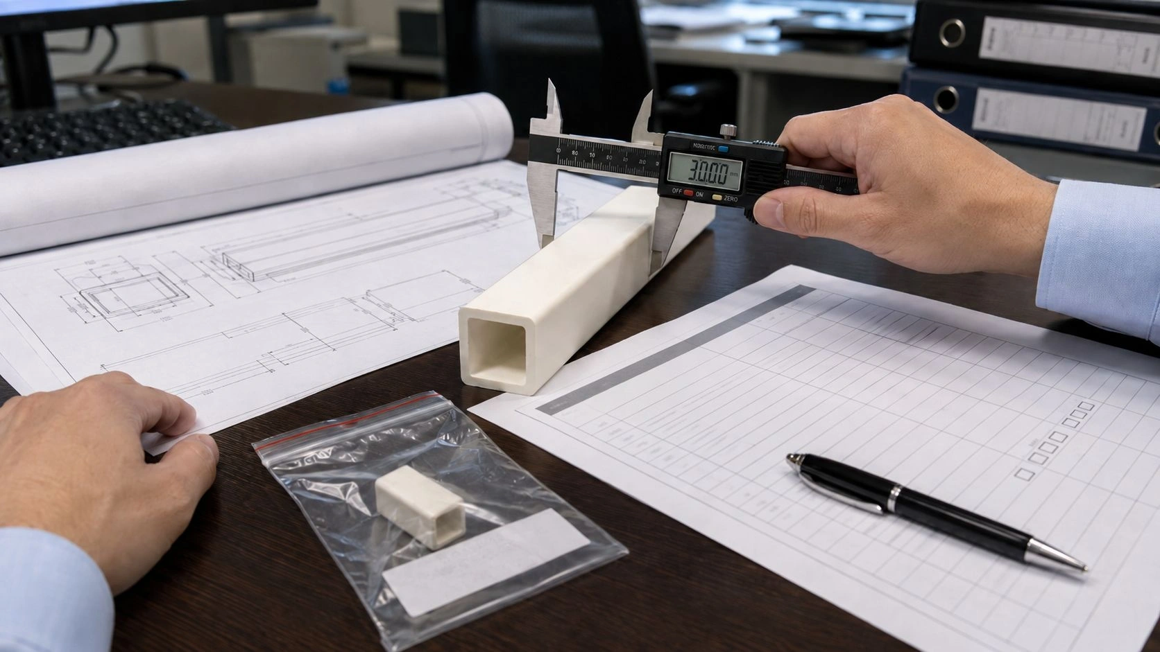
A workable RFQ for alumina ceramic tubes above 1500°C asks for more than "99% alumina." It requests chemical analysis range, bulk density and open porosity method, average grain size measurement method, any grain-boundary dopant or sintering-aid disclosure, elevated-temperature flexural strength data, creep or stress-rupture data when available, geometry tolerances, recommended support span and orientation, and atmosphere limits.
Where direct creep data are unavailable, ask what surrogate data exist under ASTM C1211 elevated-temperature flexural strength, C1291 tensile creep, or C1525 thermal shock. Equally important: ask the supplier to state what they do not guarantee. That single sentence often separates design-grade ceramics from catalog-grade ceramics. An RFQ omitting the atmosphere specification — air vs. inert vs. vacuum — is the most common reason vendor quotes diverge by 2–3× on nominally identical alumina tubes.
The minimum data package for any tube specified into 1500°C+ continuous service:
- Chemical analysis with guaranteed range, not nominal
- Bulk density and open porosity per ASTM C20 or C830
- Average grain size with measurement method named
- Sintering aid and dopant disclosure
- Elevated-temperature flexural strength per ASTM C1211, at the actual service temperature band
- Creep or stress-rupture evidence per ASTM C1291 if duty includes long holds under load
- Permeability per ASTM C577 if atmosphere isolation matters
- Supplier-recommended support span and orientation, in writing
This checklist supports the procurement file and the engineering qualification record simultaneously.
Conclusion
Above 1500°C, alumina tube selection divides on microstructure under service condition, not on temperature rating. Grain size matters — usually in the direction opposite to room-temperature intuition — but it operates inside a system that includes boundary chemistry, porosity, density, span, load, and atmosphere. The recommendation flips when continuous hold time grows, when geometry forces horizontal load on long spans, or when atmosphere chemistry pushes purity to dominate. The clean engineering position is to specify a creep-resistant microstructural window and require the supplier to prove it, rather than to buy a temperature label.
Drafting an RFQ for alumina tubes specified into continuous service above 1500°C? Send the peak temperature, hold profile, atmosphere, span, and load. ADCERAX engineers return a microstructure recommendation, density and purity targets, elevated-temperature data requirements, and a priced quote within three business days. The engineer who replies is the one who writes the spec.
FAQ
Does larger grain size always mean better creep resistance in alumina tubes?
No. Larger grain size often reduces grain-boundary area and can lower diffusion-assisted creep sensitivity, but the decision is not single-variable. Boundary chemistry, porosity, residual glassy phases, applied stress, and service geometry can outweigh average grain size in real tubes operating above 1500°C.
Why is a 1700°C alumina tube sometimes still a poor choice for continuous service?
Peak temperature tolerance and long-term dimensional stability are different questions. A tube may survive the setpoint but creep, sag, contaminate the process, or lose straightness if hold time, span, atmosphere, or load exceed what the catalog rating implicitly assumes about service envelope.
How can I tell whether a failed alumina tube had a creep problem or a thermal-shock problem?
Creep appears as progressive bowing, distortion, or dimensional drift correlated with cumulative hours at temperature. Thermal shock appears as abrupt cracking or spalling correlated with a specific ramp or quench event. If the tube is long, horizontal, or poorly supported, span-induced bending must also be ruled out.
What is the minimum supplier data package I should ask for above 1500°C?
Request guaranteed chemistry, bulk density and open porosity per ASTM C20 or C830, average grain size with method named, dopant or sintering-aid disclosure, elevated-temperature strength per ASTM C1211, atmosphere limits, and recommended support geometry. Ask whether creep data exist under ASTM C1291.