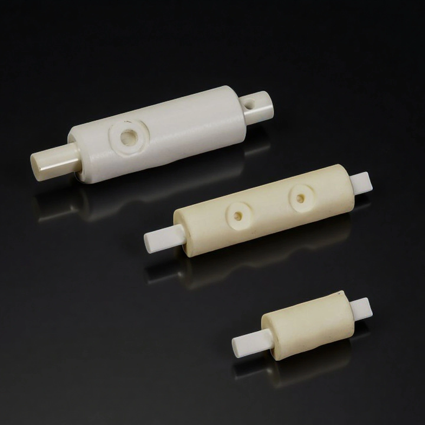
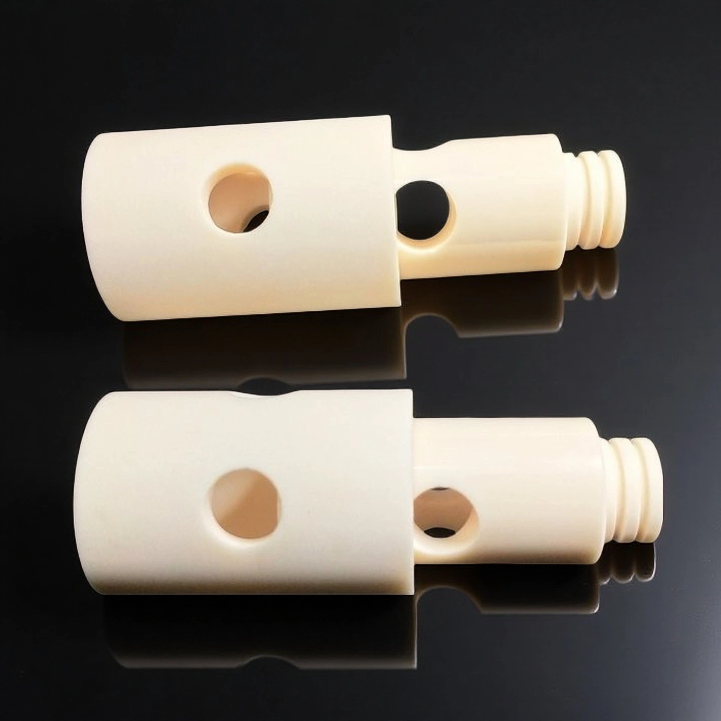
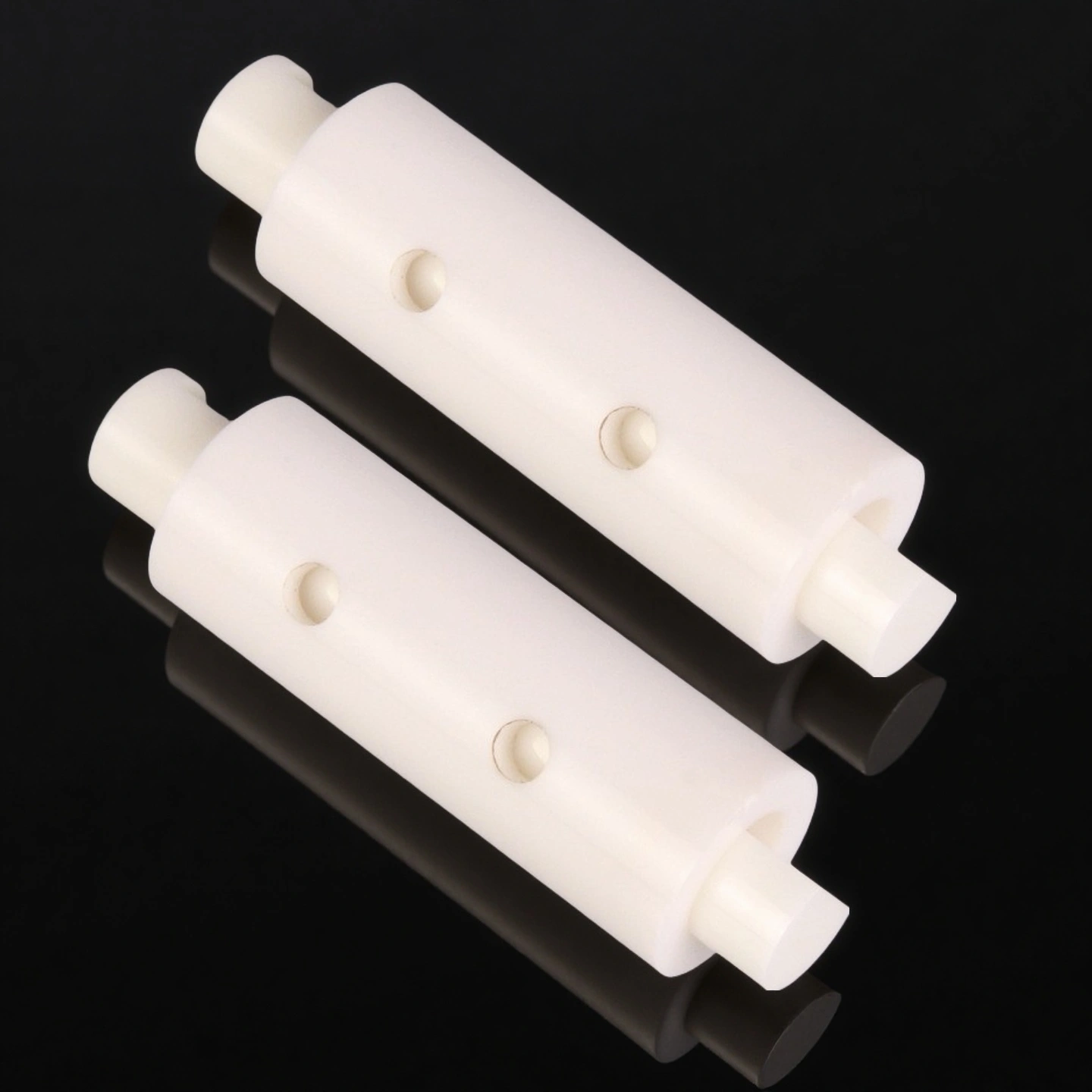
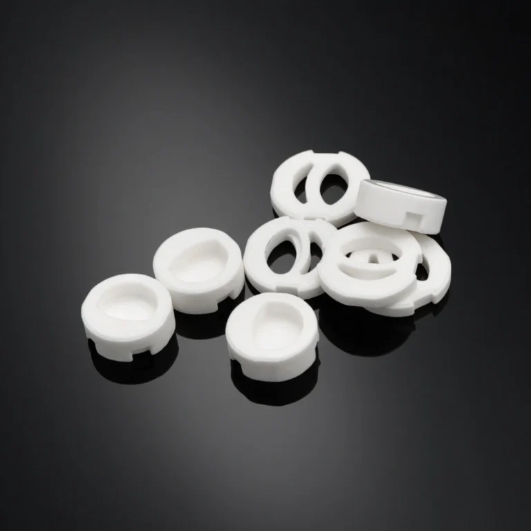
The alumina ceramic dispensing valve is a precision-engineered flow control component designed to accurately dispense adhesives, sealants, paints, and other viscous or reactive fluids in industrial automation and production lines.
Alumina Ceramic Dispensing Valve Benefits
- Wear resistance in filled media — ceramic seat/nozzle maintains flow in high-filler epoxies and TIMs.
- Low residue adhesion — polished alumina bore reduces stringing and clog initiation on CA/UV lines.
- Tight sealing — fine lapping and concentricity improve air-tightness and reduce micro-leaks.
- Thermal stability — low CTE geometry sustains dot size across temperature changes.
- Chemical inertness — compatible with many aggressive solvents and monomers; avoids media contamination.
Properties of Alumina Ceramic Dispensing Valve
|
Property |
Unit |
99.5% Al₂O₃ |
99.6% Al₂O₃ |
99.7% Al₂O₃ |
99.8% Al₂O₃ |
99.9% Al₂O₃ |
99.99% Al₂O₃ |
|
Alumina content |
% |
99.5 |
99.6 |
99.7 |
99.8 |
99.9 |
99.99 |
|
Density |
g/cm³ |
3.89 |
3.91 |
3.92 |
3.93 |
3.94 |
3.98 |
|
Open porosity |
% |
0 |
– |
– |
– |
– |
– |
|
Color |
– |
Ivory |
Ivory |
Ivory |
Ivory |
Ivory |
Ivory |
|
Water absorption |
% |
– |
0 |
0 |
0 |
0 |
0 |
|
Young’s modulus (Elastic modulus) |
GPa |
375 |
356 |
357 |
358 |
359 |
362 |
|
Shear modulus |
GPa |
152 |
– |
– |
– |
– |
– |
|
Bulk modulus |
GPa |
228 |
– |
– |
– |
– |
– |
|
Poisson’s ratio |
– |
0.22 |
– |
– |
– |
– |
– |
|
Compressive strength |
MPa |
2600 |
2552 |
2554 |
2556 |
2558 |
2570 |
|
Flexural strength |
MPa |
379 |
312 |
313 |
314 |
315 |
320 |
|
Fracture toughness |
MPa·m¹ᐟ² |
4 |
– |
– |
– |
– |
– |
|
Hardness |
GPa |
14.1 (≈1440 kg/mm²) |
23 |
24 |
25 |
26 |
30 |
|
Thermal conductivity |
W/m·K |
35 |
32–37 |
33–38 |
34–39 |
35–40 |
36–42 |
|
Thermal shock resistance ΔT |
°C |
– |
222 |
223 |
224 |
225 |
228 |
|
Maximum use temperature (no load) |
°C |
≤1750 |
1755 |
1760 |
1765 |
1770 |
1800 |
|
Coefficient of thermal expansion |
10⁻⁶/°C |
8.4 |
– |
– |
– |
– |
– |
|
Specific heat |
J/kg·K |
880 |
– |
– |
– |
– |
– |
|
Volume resistivity |
Ω·cm |
>1×10¹⁴ |
>1×10¹⁴ |
>1×10¹⁴ |
>1×10¹⁴ |
>1×10¹⁴ |
>1×10¹⁴ |
|
Dielectric constant (relative permittivity) |
– |
9.8 |
9.83 |
9.84 |
9.85 |
9.86 |
9.92 |
|
Dielectric strength |
kV/mm |
16.9 |
23.2 |
23.4 |
23.6 |
23.8 |
24 |
|
Dissipation factor (loss factor @ 1 kHz) |
– |
0.0002 |
– |
– |
– |
– |
– |
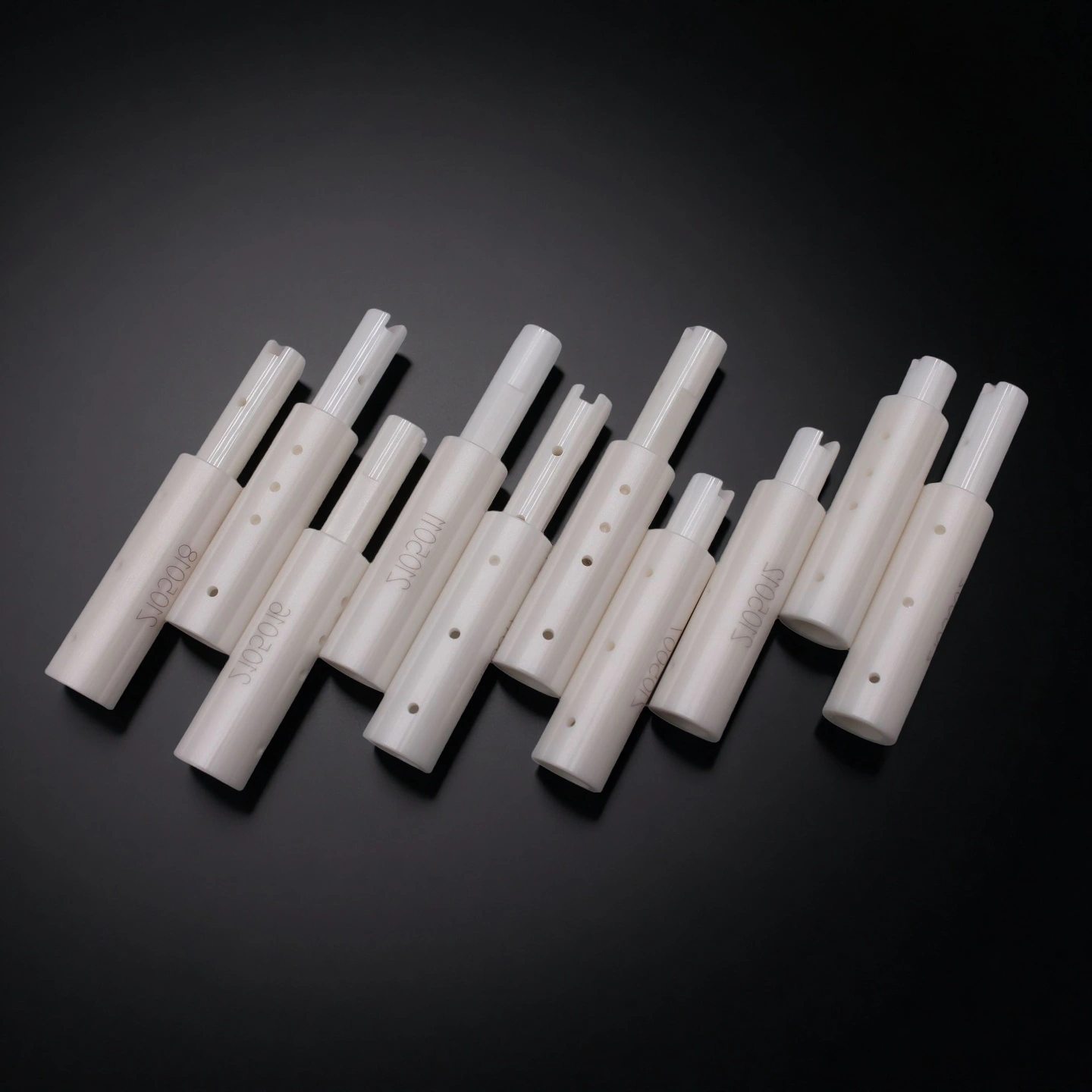
Alumina Ceramic Dispensing Valve Specifications
|
Item |
Size (mm) |
Diameter(mm) |
Length (mm) |
Purity(%) |
|
AT-YHL-DJF001 |
5*70 |
5 |
70 |
99 |
|
AT-YHL-DJF002 |
23*85 |
23 |
85 |
99 |
|
AT-YHL-DJF003 |
25*105 |
25 |
105 |
99 |
|
AT-YHL-DJF004 |
30*120 |
30 |
120 |
99 |
|
AT-YHL-DJF005 |
40*120 |
40 |
120 |
99 |
|
AT-YHL-DJF006 |
50*150 |
50 |
150 |
99 |
|
AT-YHL-DJF007 |
80*200 |
80 |
200 |
99 |
|
AT-YHL-DJF008 |
100*220 |
100 |
220 |
99 |
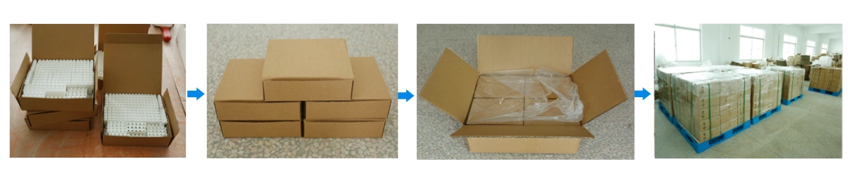
Alumina Ceramic Dispensing Valve Packaging
- Packaging: Individually foam-protected, anti-static bag sealed
- Standard carton: Multi-layer impact-protection
Usage Instructions: Alumina Ceramic Dispensing Valve
Proper installation, operation, and maintenance of the alumina ceramic dispensing valve directly influence dispensing accuracy, valve life, and production efficiency. Follow these guidelines to achieve stable and consistent performance in automated adhesive applications.
-
Installation
1. Manifold Preparation: Ensure manifold flatness and precise alignment before mounting. Torque bolts to the specified value to prevent ceramic seat distortion.
2. System Cleaning: Flush the fluid line with a compatible solvent before installation to remove old adhesive or particulates.
3. Filtration Setup: Always install an upstream 50–100 µm precision filter to prevent filler particles or dust from entering the orifice.
4. Calibration: Run initial dot calibration at operating temperature; record baseline pressure, cycle time, and dot volume for future reference.
5. Seal Inspection: Check all O-rings and PTFE/FFKM seals before assembly; replace aged or swollen components to maintain air-tightness.
-
Operation
1. Pressure Control: Keep inlet pressure within the validated range for the adhesive’s viscosity and nozzle size. Excess pressure can enlarge dots or shorten valve life.
2. Purging Cycle: Schedule timed purges (every 30–60 minutes for reactive adhesives) to prevent gel or residue buildup near the seat area.
3. Performance Monitoring: Inspect first-article dots each shift; record CV and mean volume. Adjust timing or pressure by micro-steps if deviation exceeds ±3%.
4. Temperature Management: For high-viscosity adhesives, pre-heat the fluid reservoir (40–60 °C range) to stabilize flow rate, but avoid direct heating on the ceramic valve body.
5. Cycle Rate: Recommended duty cycle ≤ 10 Hz for high-viscosity adhesives; consult engineering for higher-speed setups.
-
Storage
1. After Reactive Use: Purge the valve with appropriate solvent until discharge is clear. Dry with clean nitrogen and cap both ports to avoid dust entry.
2. Environmental Conditions: Store in a cool, dry place (20–30 °C, RH < 60%) away from UV and direct heat.
3. Long-Term Storage: For valves inactive over 3 months, relubricate plunger seals before reuse to avoid startup leakage.
-
Cleaning & Inspection
1. Routine Cleaning: Disassemble per the assembly drawing. Soak the nozzle and seat in approved solvent (e.g., acetone, ethanol, or MEK, depending on adhesive type).
2. Surface Protection: Never use metallic brushes or abrasive tools on the ceramic bore. Use soft nylon or lint-free swabs.
3. Visual Check: Examine the seat and plunger under magnification; any visible nicks or scratches require replacement.
4. Reassembly: Reinstall parts gently; apply even torque. Verify that there is no misalignment or trapped particles at the sealing surfaces.
-
Common Mistakes & Fixes
1. Volume drift in filled epoxy→ Increase upstream filter area; verify internal diameter wear; switch to finer polish grade; recalibrate at process temperature.
2. CA or UV adhesive stringing → Shorten shut-off delay (0.01–0.03 s); upgrade to mirror-polished Ra ≤ 0.2 µm bore; validate anti-bloom solvent purge before downtime.
3. Post-heat leakage or dripping → Re-specify seals for high-temperature range; check plunger runout ≤ 0.03 mm; re-lap seat surface if leakage persists.
4. Dot-size inconsistency after long run → Inspect adhesive temperature stability; recheck air pressure regulator and cycle timing accuracy.
5. Premature seat wear → Confirm adhesive filler hardness (e.g., Al₂O₃, BN); consider ceramic seat with increased density or alternate bore geometry.