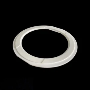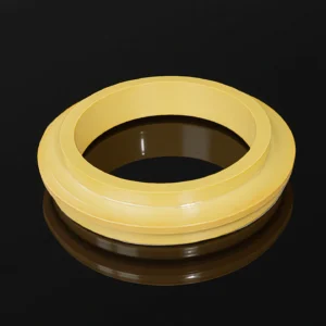
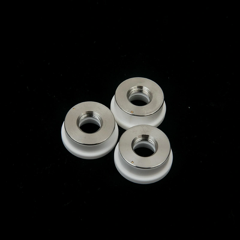
Ceramic ring for a laser cutting machine is a small insulating and positioning component installed between the nozzle and the contact/sensing assembly of the laser cutting head. Its job is to isolate the contact pin electrically, keep the nozzle coaxial with the optical axis, and maintain a consistent sensor gap so the head can trigger correctly during piercing and cutting.
Ceramic Ring for Laser Cutting Machine Benefits
- Low runout interface — nozzle coaxiality supported by concentricity targets (≤0.10 mm).
- Defined thickness stack-up — ring thickness tolerance (±0.05–±0.10 mm) stabilizes sensor gap.
- Material fit for duty — Al₂O₃ for standard use; ZTA option for impact-prone changeovers.
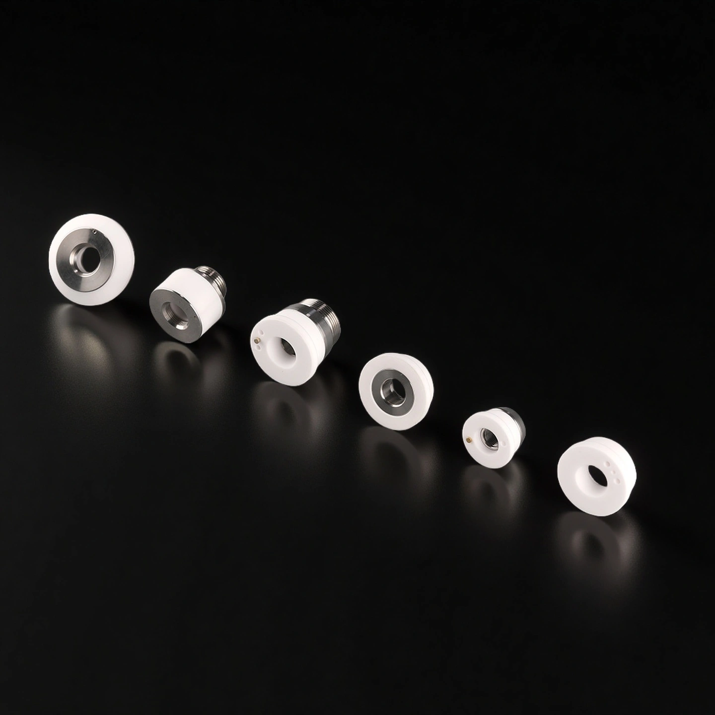
- Thread/model mapping — D28/M11, D32/M14, D41/M11 options reduce compatibility errors.
- Edge integrity — controlled chamfers to lower chip initiation during nozzle swaps.
What This Ceramic Ring Does in a Fiber Laser Cutting Head
A ceramic ring for a laser cutting machine is installed near the nozzle and sensing assembly of a fiber laser cutting head. Its role is not only insulation. It also helps maintain nozzle position, sensing contact stability and repeatable seating during nozzle replacement.
When the ring height, thread, seating face or contact layout is incorrect, the cutting head may show false trigger alarms, unstable capacitance sensing, inconsistent piercing or kerf offset after service. For this reason, the ceramic ring should be selected by size, thread, head model and actual assembly condition, not by outer diameter alone.
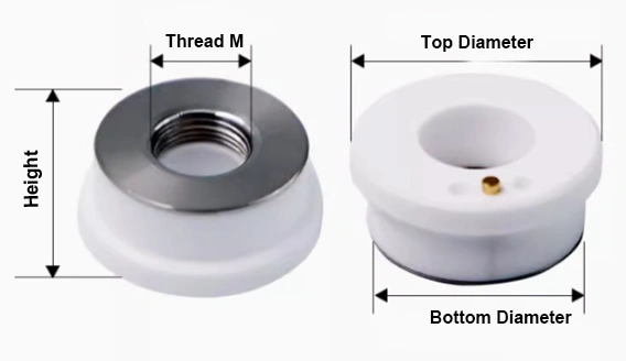
Ceramic Ring for Laser Cutting Machine Specifications
| Ceramic Ring for Laser Cutting Machine | |||||
| Item NO. | Name | Maximum Outer Dia.(mm) | Lower Outer Dia.(mm) | Height(mm) | M(Thread) |
| AT-D32M14 | Ceramic Rings | 32 | 28 | 12 | M14 |
| AT-D28M11 | Ceramic Rings | 28 | 24.5 | 12 | M11 |
| AT-D25M10 | Ceramic Rings(OSPR) | 25 | 18 | 19 | M10 |
| AT-D21.5M8 | Ceramic Rings(OSPR-3D) | 21.5 | — | 14 | M8 |
| AT-D24M8 | Ceramic Rings(WSX-Mini) | 24 | 20 | 12 | M8 |
| AT-D17.8M8 | Ceramic Rings(OSPR-3D) | 17.8 | 15 | 12.6 | M8 |
| AT-D19.5M8 | Ceramic Rings(JQ-3D) | 19.5 | 16 | 12.5 | M8 |
| AT-D31M11 | Ceramic Rings(PLST) | 31 | 26 | 13.5 | M11 |
| AT-D28.7M11 | Ceramic Rings(IPG) | 28.7 | 23.3 | 10.5 | M11 |
| AT-D32M12 | Ceramic Rings(TL) | 32 | 28 | 12 | M12 |
| AT-D28M12 | Ceramic Rings(TL) | 28 | 24.5 | 12 | M12 |
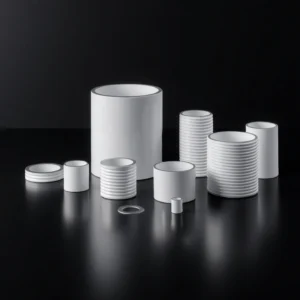
Material Selection: Alumina vs ZTA
Most laser cutting ceramic rings use alumina ceramic because it provides stable electrical insulation, good dimensional control and cost-effective replacement for common cutting head service. Alumina is suitable for standard spare-part kits, maintenance replacement and normal nozzle change frequency.
ZTA can be selected when the ring is exposed to frequent handling, repeated nozzle replacement or higher impact risk during maintenance. Compared with standard alumina, ZTA gives better toughness and can help reduce edge chipping risk in demanding replacement environments.
The material should be selected according to head structure, replacement frequency, impact risk, required insulation behavior and whether the ring includes metal contact components. ADCERAX can review the old ring, drawing or assembly photo before confirming the suitable material route.
Why Ring Accuracy Affects Cutting Stability
A laser head ceramic ring looks simple, but small dimensional errors can affect the cutting head response. If the ring height is too high or too low, the sensor gap may shift. If the seating face is not stable, the nozzle may not stay coaxial with the cutting head. If the edge chips during installation, the contact path may become unstable.
For maintenance teams, the most visible problems are false trigger alarms, repeated calibration, unstable piercing and kerf offset after nozzle replacement. For OEM and after-sales projects, the main concern is batch consistency. Rings supplied in the same kit should have controlled height, thread fit, seating face and visual quality to reduce field installation problems.
Common Failure Modes and Replacement Signs
| Failure Sign | Possible Cause | What to Check |
|---|---|---|
| False trigger alarm | Contaminated surface, poor contact or chipped edge | Check sensor contact area, ring edge and installation face. |
| Kerf offset after nozzle change | Ring height or seating face mismatch | Compare old ring height, lower OD and thread type. |
| Ring cracks during installation | Excessive torque or edge impact | Review tightening method and packaging protection. |
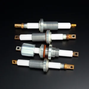
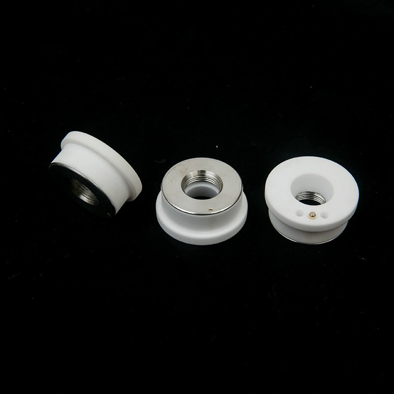
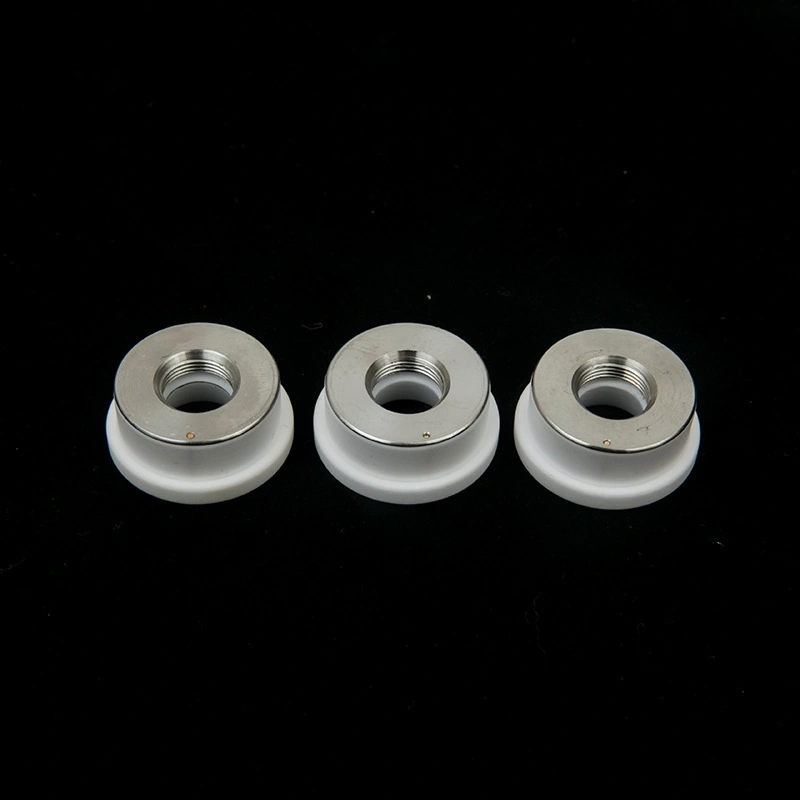
| Unstable capacitance sensing | Metal contact or ceramic insulation issue | Check copper pin, stainless contact and ceramic body condition. |
| Frequent recalibration | Batch inconsistency or incorrect model | Confirm model mapping and dimensional tolerance before reorder. |
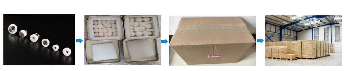
Ceramic Ring for Laser Cutting Machine Packaging
- Ceramic rings for laser cutting machines should be packed separately to prevent edge impact, thread damage and model mixing during transport. ADCERAX can use separated foam trays, anti-static bags, carton protection and size labels according to order requirements.
- For mixed-size orders, D28/M11, D32/M14, D41/M11 and other models should be separated clearly. This helps maintenance teams identify the correct ring quickly and reduces wrong installation during nozzle replacement.