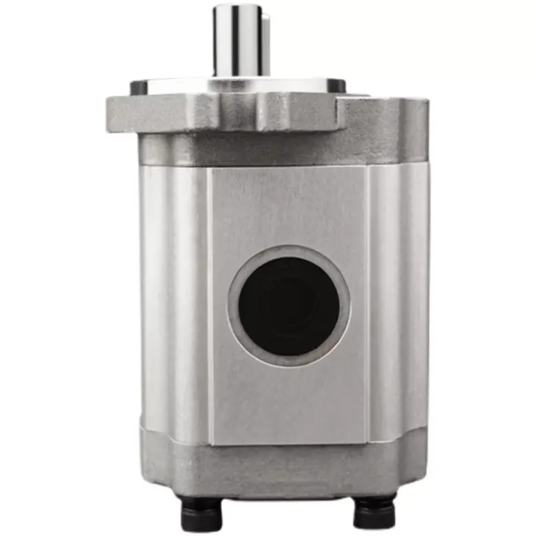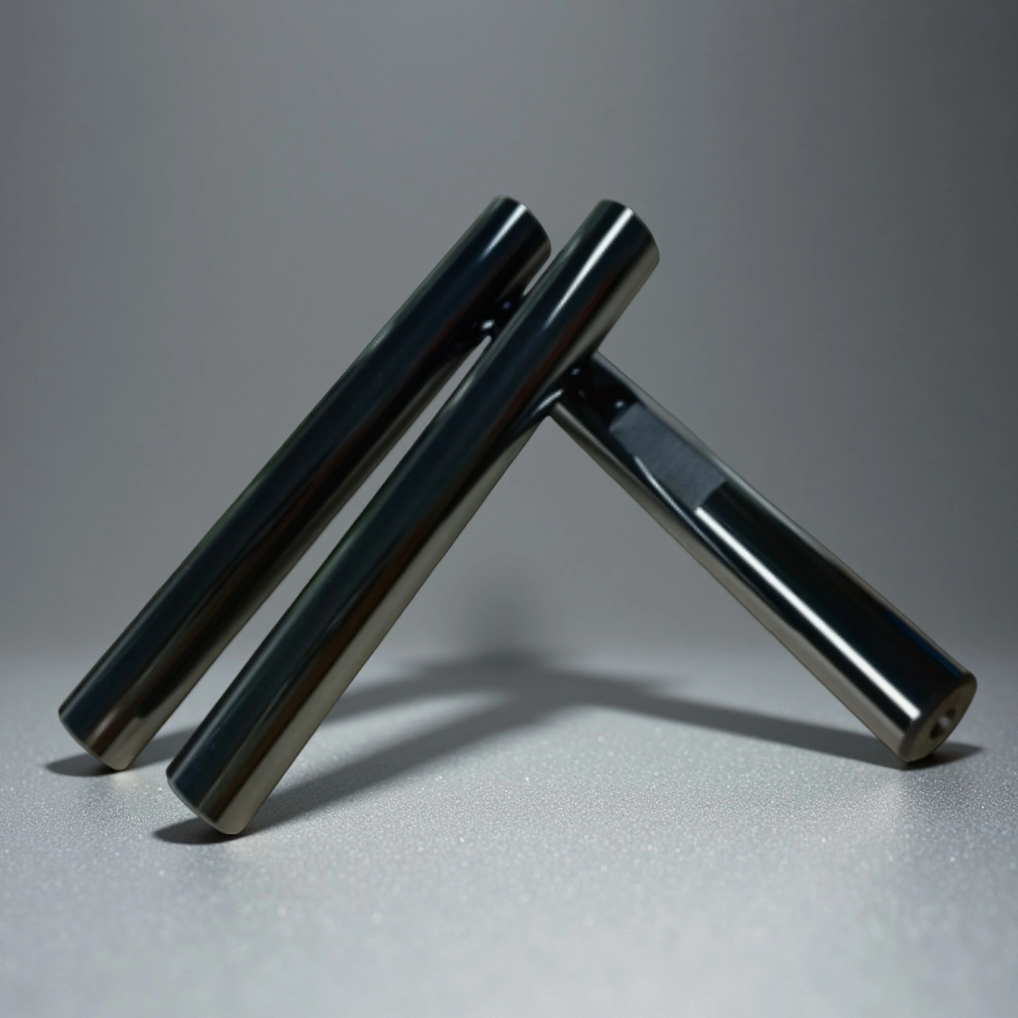
A silicon carbide shaft is a precision ceramic rotating component used in pumps and fluid-handling systems where metal shafts may suffer from corrosion, abrasive wear, chloride pitting or thermal distortion. ADCERAX provides custom SiC shafts made from sintered silicon carbide or reaction-bonded silicon carbide for chemical pumps, slurry pumps, magnetic drive pumps and desalination equipment.
Performance Characteristics of Silicon Carbide Shaft in Industrial Systems
-
Strength retention above 1200 °C
The shaft maintains structural integrity during prolonged thermal exposure, preventing deformation in reactors and heated pump systems. This behavior supports stable load transfer across continuous-duty operations. -
Hardness measured at 23–26 GPa
High hardness minimizes abrasive loss in particle-rich chemical slurries and reduces surface degradation over long service cycles. Its wear stability maintains smooth shaft rotation and reduces vibration. -
Thermal expansion coefficient around 4.0 × 10⁻⁶/K
Low expansion minimizes internal stress buildup in high-temperature systems and prevents misalignment during thermal cycling. This contributes to consistent rotation in heated pump stages. -
Surface roughness controllable to Ra 0.2 µm
Polished surfaces reduce friction at bearing interfaces and help maintain lubrication behavior. This supports extended operation at high rotational speeds. -
Friction coefficient near 0.15
Controlled friction behavior reduces heat generation and contact stress during rotation. This supports consistent movement in equipment exposed to particulate contamination.
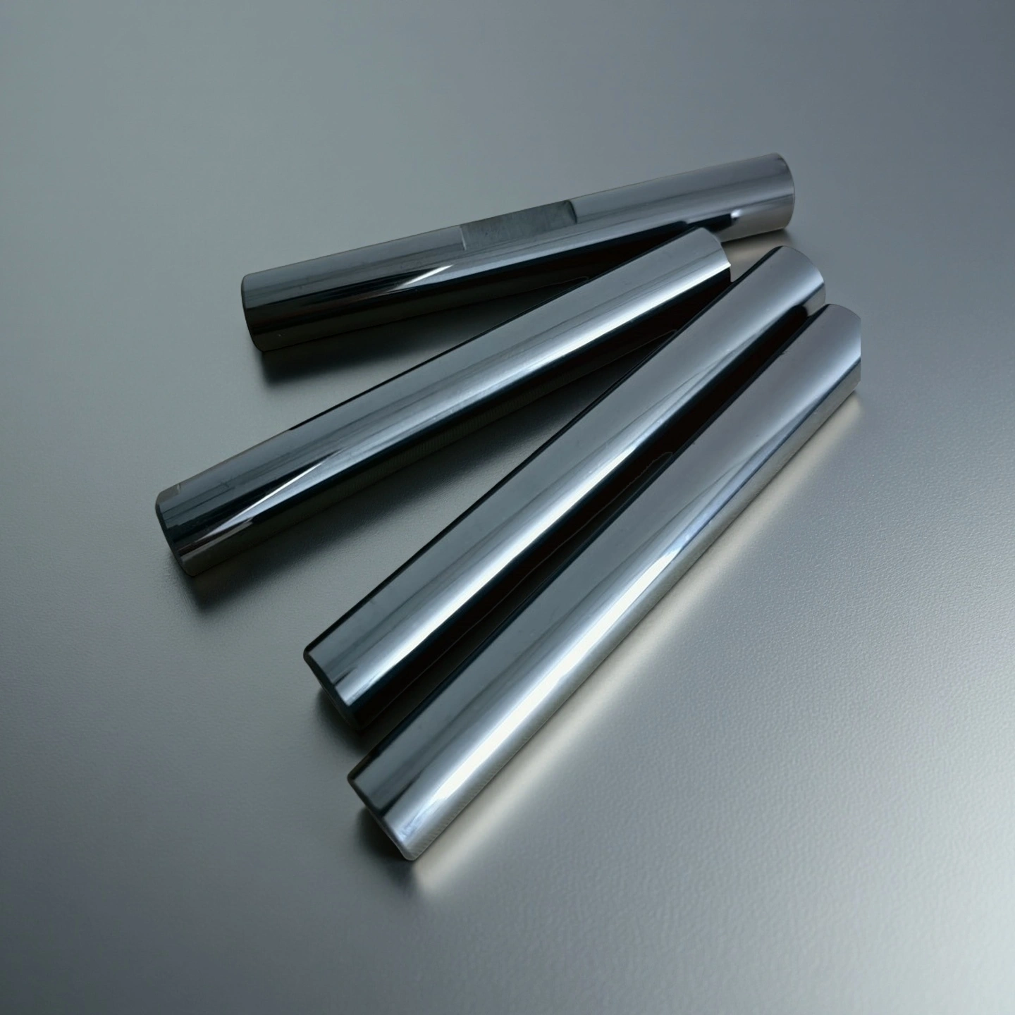
Engineering Performance Factors for Silicon Carbide Pump Shaft Design
The Silicon Carbide Shaft demonstrates stable mechanical, thermal, and chemical behavior under corrosive liquids, high-temperature cycles, and abrasive slurry conditions, making it suitable for evaluation by laboratory testing institutions and industrial material qualification processes.
| Engineering Factor | Typical Reference Data | What It Means for Pump Design |
|---|---|---|
| Material Grade | SSiC or RBSiC | The material grade affects corrosion resistance, wear behavior, size capability and cost. |
| Density | 3.10–3.15 g/cm³ | Density helps evaluate material compactness, shaft weight and assembly balance. |
| Hardness | 23–26 GPa | High hardness helps reduce abrasive wear in slurry and particle-loaded pump media. |
| Flexural Strength | 350–450 MPa | Flexural strength matters when the shaft faces bending load or wide bearing spacing. |
| Compressive Strength | 2000–2500 MPa | High compressive strength supports contact pressure from bearings, sleeves and seals. |
| Elastic Modulus | 380–420 GPa | High rigidity helps control shaft deflection in rotating pump assemblies. |
| Thermal Conductivity | 80–120 W/m·K | Thermal conductivity helps transfer local heat away from contact areas. |
| Thermal Expansion Coefficient | 4.0 × 10⁻⁶/K | Low expansion helps maintain alignment during temperature changes. |
| Thermal Shock Behavior | Application-dependent | This should be reviewed when pumps experience rapid heating, cooling or start-stop cycles. |
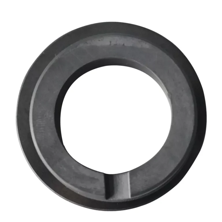
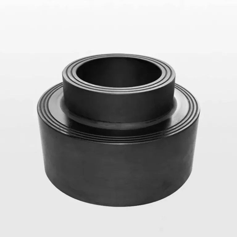
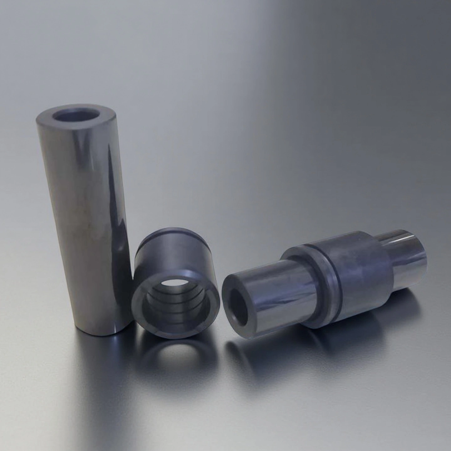
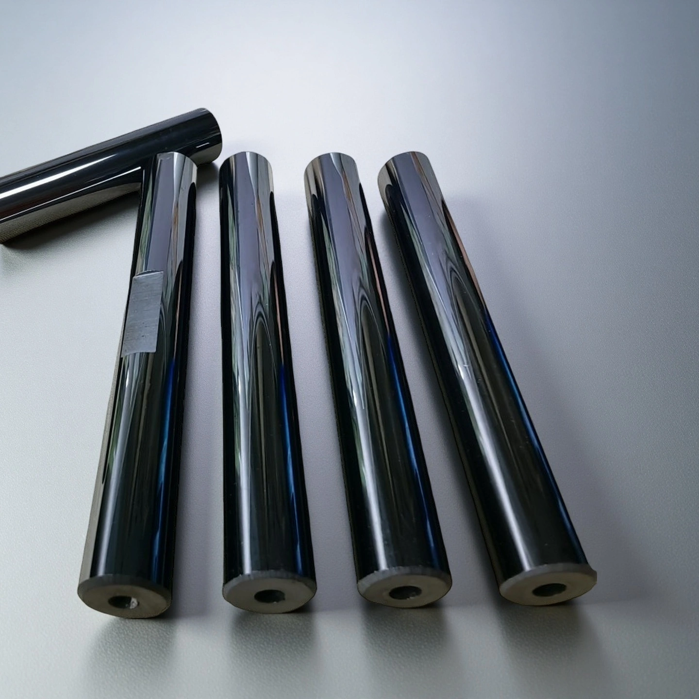
Dimensions of Silicon Carbide Shaft
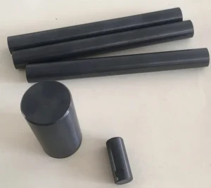
| SiC Shaft with Solid | |||
| Item No. | Diameter (mm) | Length (mm) | Purity(%) |
| AT-SCB-001 | 8 | 10-500 | 85-99 |
| AT-SCB-002 | 10 | 10-500 | 85-99 |
| AT-SCB-003 | 12 | 10-500 | 85-99 |
| AT-SCB-004 | 17 | 10-500 | 85-99 |
| AT-SCB-005 | 20 | 20-500 | 85-99 |
| AT-SCB-006 | 22 | 20-500 | 85-99 |
| AT-SCB-007 | 28 | 20-500 | 85-99 |
| AT-SCB-008 | 31 | 40-500 | 85-99 |
| AT-SCB-009 | 45 | 40-500 | 85-99 |
| AT-SCB-010 | 50 | 40-500 | 85-99 |
| AT-SCB-011 | 83 | 40-500 | 85-99 |
| AT-SCB-012 | 92 | 80-500 | 85-99 |
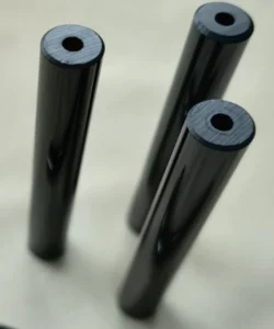
| SiC Shaft with Hollow | ||||
| Item No. | Outer Diameter (mm) | Inner Diameter (mm) | Length (mm) | Purity(%) |
| AT-SCG-001 | 16 | 6 | 42 | 85-99 |
| AT-SCG-002 | 16 | 8 | 42 | 85-99 |
| AT-SCG-003 | 18 | 10 | 42 | 85-99 |
| AT-SCG-004 | 20 | 10 | 45 | 85-99 |
| AT-SCG-005 | 24 | 12 | 51 | 85-99 |
| AT-SCG-006 | 24 | 12 | 51 | 85-99 |
| AT-SCG-007 | 24 | 10 | 51 | 85-99 |
| AT-SCG-008 | 25 | 12 | 56 | 85-99 |
| AT-SCG-009 | 28 | 14 | 60 | 85-99 |
| AT-SCG-010 | 28 | 14 | 70 | 85-99 |
| AT-SCG-011 | 28 | 14 | 70 | 85-99 |
| AT-SCG-012 | 28 | 14 | 60 | 85-99 |
| AT-SCG-013 | 30 | 16 | 70 | 85-99 |
| AT-SCG-014 | 30 | 16 | 70 | 85-99 |
| AT-SCG-015 | 32 | 16 | 85 | 85-99 |
| AT-SCG-016 | 32 | 16 | 85 | 85-99 |
| AT-SCG-017 | 32 | 18 | 85 | 85-99 |
| AT-SCG-018 | 32 | 18 | 85 | 85-99 |
| AT-SCG-019 | 32 | 20 | 85 | 85-99 |
| AT-SCG-020 | 32 | 20 | 85 | 85-99 |
| AT-SCG-021 | 32 | 15 | 85 | 85-99 |
| AT-SCG-022 | 32 | 15 | 85 | 85-99 |
| AT-SCG-023 | 32 | 22 | 85 | 85-99 |
| AT-SCG-024 | 32 | 22 | 85 | 85-99 |
| AT-SCG-025 | 32 | 18 | 74 | 85-99 |
| AT-SCG-026 | 32 | 18 | 74 | 85-99 |
| AT-SCG-027 | 40 | 20 | 85 | 85-99 |
| AT-SCG-028 | 44 | 25 | 108 | 85-99 |
| AT-SCG-029 | 49 | 25 | 108 | 85-99 |
| AT-SCG-030 | 49 | 30 | 108 | 85-99 |
| AT-SCG-031 | 49 | 28 | 108 | 85-99 |
| AT-SCG-032 | 49 | 25 | 108 | 85-99 |
| AT-SCG-033 | 49 | 25 | 108 | 85-99 |
| AT-SCG-034 | 49 | 24 | 108 | 85-99 |
| AT-SCG-035 | 49 | 25 | 108 | 85-99 |
| AT-SCG-036 | 58 | 35 | 140 | 85-99 |
| AT-SCG-037 | 58 | 30 | 123 | 85-99 |
| AT-SCG-038 | 68 | 40 | 150 | 85-99 |
SSiC vs RBSiC Silicon Carbide Shaft Selection
ADCERAX can review sintered silicon carbide and reaction-bonded silicon carbide options according to the pump media, load condition, dimensional requirement and cost target.
SSiC shafts are usually selected when high chemical resistance, wear stability and dense ceramic performance are required in aggressive media.
RBSiC shafts may be considered when larger or more complex shapes are needed and the operating conditions match the material’s application range.
Before quotation, our team reviews the working fluid, particle content, operating temperature, rotational speed, shaft size, end structure and mating parts to help select a practical SiC material route.
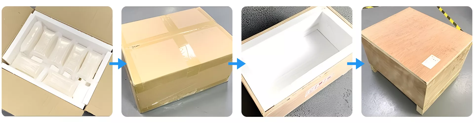
Packaging Method for Silicon Carbide Shaft
Silicon Carbide Shaft is protected using multi-layer cushioning that secures each component in an impact-absorbing inner tray. The sealed carton is then reinforced with a rigid wooden crate to prevent vibration and structural stress during long-distance transport. This packaging method ensures stable handling from factory dispatch to end-user installation.