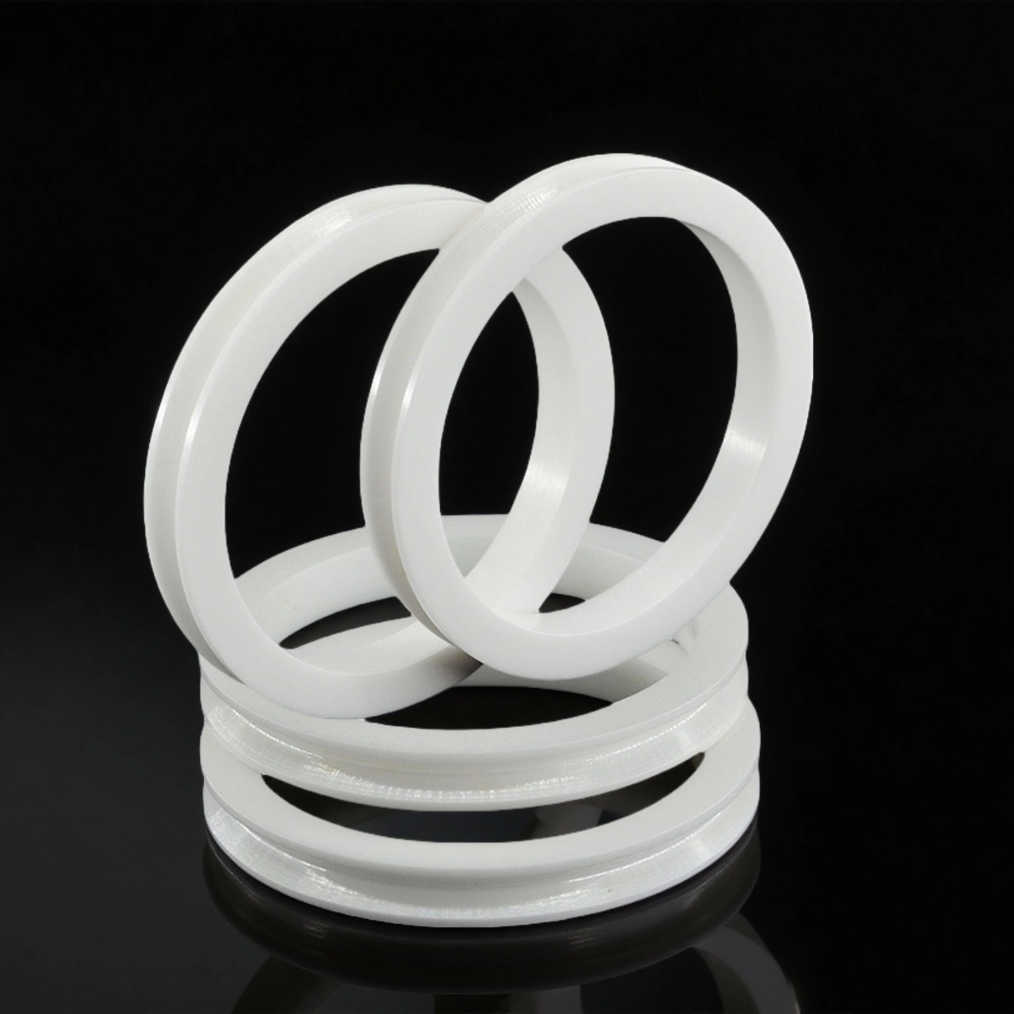
Abrasion-Controlled Zirconia Ceramic Wire Wheel for Wire Conversion Facilities
The Zirconia Ceramic Wire Wheel is engineered to perform under high-tension, high-speed conditions where dimensional stability and long wear life are critical. Its thermal, mechanical, and surface attributes contribute directly to reduced downtime, stable wire handling, and long-term operational reliability.
ADCERAX® Zirconia Ceramic Wire Wheel is designed for industrial wire drawing, stranding, and tensioning processes that demand stability and wear resistance under high load. It delivers consistent wire guidance across continuous production lines for copper, aluminum, and alloy conductors. Its high mechanical strength and polished surface reduce wire damage, extend service life, and minimize maintenance downtime. The wheel’s corrosion and heat resistance ensure reliable operation in both dry and lubricated environments.
Key Performance Characteristics of Zirconia Ceramic Wire Wheel
Fracture Toughness ≥ 8 MPa·m¹ᐟ² The Zirconia Ceramic Wire Wheel resists edge chipping and cracking under high mechanical stress, outperforming alumina ceramics by over 2.5× in dynamic loading applications.
Flexural Strength ≥ 1000 MPa It maintains integrity under repeated tensile forces in high-speed rotation environments, enabling long service life in continuous production.
Compressive Strength > 2000 MPa Suitable for heavy-load tensioning systems, it retains its structure under high axial force without material deformation.
Surface Roughness ≤ 0.2 µm (Ra) The ultra-smooth finish reduces wire friction and coating wear, critical in high-speed drawing lines with thin insulation layers.
Roundness and Concentricity ≤ 0.01 mm Precision machining ensures consistent line tension and uniform wire exit, supporting process repeatability.
Density = 6.05 g/cm³ The compact structure delivers balanced rotational mass, improving stability at speeds up to 30,000 rpm.
Continuous Temperature Resistance up to 800 °C The Zirconia Ceramic Wire Wheel performs reliably in high-heat zones such as annealing or dry drawing sections without thermal degradation.
Thermal Shock Resistance ≥ 400 °C (ΔT) It endures rapid heating and cooling cycles with no microcrack propagation, maintaining service life in fluctuating line temperatures.
Corrosion Inertness in Alkaline Emulsions Prolonged exposure to oil-based lubricants and wire drawing emulsions does not affect surface integrity, reducing replacement frequency.
Technical Properties of Zirconia Ceramic Wire Wheel
The Zirconia Ceramic Wire Wheel delivers outstanding performance under high-speed mechanical loading and thermal cycling. Its engineered composition and controlled microstructure provide exceptional strength, surface finish, and chemical stability required for modern wire processing applications.
Property
Specification
Material Composition
≥ 99.8% ZrO₂ with Y₂O₃ stabilization
Density
6.05 g/cm³
Vickers Hardness
1200–1300 HV
Fracture Toughness (KIC)
≥ 8 MPa·m¹ᐟ²
Flexural Strength
≥ 1000 MPa
Compressive Strength
> 2000 MPa
Thermal Conductivity
2.2 W/m·K @ 20°C
Maximum Operating Temperature
800 °C continuous, 1000 °C short-term
Thermal Shock Resistance
ΔT ≥ 400 °C
Surface Roughness (Ra)
≤ 0.2 µm (polished)
Chemical Stability
Inert to oils, alkaline emulsions, drawing fluid
Grain Size
≤ 0.5 µm (submicron controlled)
Open Porosity
< 0.1%
Phase Composition
≥ 95% tetragonal phase retained
Specifications of Zirconia Ceramic Wire Wheel
Zirconia Ceramic Wire Wheel
Catalogue No.
Outer Diameter (mm)
Bearing Bore D (mm)
Height (mm)
Groove Type
AT-YHG-L1001
14
3
6
V-Groove
AT-YHG-L1002
15
3
4
V-Groove
AT-YHG-L1003
23
4
10
U-Groove
AT-YHG-L1004
23
5
9
U-Groove
AT-YHG-L1005
26
4
10.5
U-Groove
AT-YHG-L1006
26
5
10.5
U-Groove
AT-YHG-L1007
26
6
10.5
U-Groove
AT-YHG-L1008
30
5
11
U-Groove
AT-YHG-L1009
30
6
11
U-Groove
AT-YHG-L1010
30
8
11
U-Groove
AT-YHG-L1011
32
5
20
V-Groove
AT-YHG-L1012
32
6
20
V-Groove
AT-YHG-L1013
35
5
10
U-Groove
AT-YHG-L1014
35
6
10
U-Groove
AT-YHG-L1015
35
8
10
U-Groove
AT-YHG-L1016
40
4
12
U-Groove
AT-YHG-L1017
40
5
24
U-Groove
AT-YHG-L1018
40
6
24
U-Groove
AT-YHG-L1019
45
8
14
U-Groove
AT-YHG-L1020
45
10
16
U-Groove
AT-YHG-L1021
45
10
16
V-Groove
AT-YHG-L1022
50
8
16
V-Groove
AT-YHG-L1023
50
10
18
V-Groove
AT-YHG-L1024
60
8
13
V-Groove
AT-YHG-L1025
60
10
13
V-Groove
AT-YHG-L1026
60
8
18
U-Groove
AT-YHG-L1027
72
12
25
V-Groove
AT-YHG-L1028
76
9
25
V-Groove
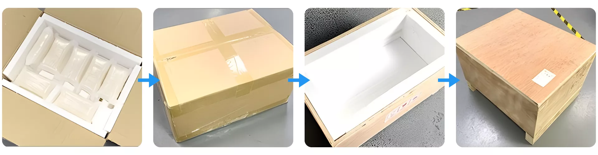
Packaging of Zirconia Ceramic Wire Wheel
Zirconia Ceramic Wire Wheel is first individually cushioned in custom foam trays to prevent vibration and collision during transit. The inner foam box is sealed and then double-layered with an outer corrugated carton for added compression resistance. For international shipping, the entire unit is secured in a reinforced wooden crate with full internal lining to ensure impact protection and moisture isolation.
ADCERAX® Zirconia Ceramic Wire Wheel addresses performance bottlenecks in industrial wire processing lines where traditional metal or alumina wheels fail to maintain precision, wear resistance, and thermal stability. Its technical advantages enable higher uptime, reduced material waste, and smoother line tension control across demanding applications involving large-diameter or surface-sensitive wire products.
High-Tension Stranding of Large Cross-Section Conductors Using Zirconia Ceramic Wire Wheel
✅Key Advantages
1. Torsional Crack Resistance The wheel withstands complex axial and radial forces during conductor twisting due to its ≥ 8 MPa·m¹ᐟ² fracture toughness. This prevents stress-induced microcracks when processing bundled wires under dynamic torque.
2. Roundness Retention During Long Runs With a measured roundness deviation of ≤ 0.01 mm, the Zirconia Ceramic Wire Wheel maintains concentric wire payout over stranding lengths exceeding 800 meters, minimizing cumulative lay error.
3. Surface Abrasion Immunity Even after 500+ km of stranding operation with 150 mm² aluminum conductors, Ra ≤ 0.2 µm was maintained, reducing jacket wear and conductor misalignment incidents.
✅ ️Problem Solved
Lay-Length Variation and Jacket Damage in HV Stranding
A European cable plant manufacturing 3-core 185 mm² HV cables experienced inconsistent conductor lay and periodic insulation scoring due to steel pulley surface erosion. After switching to ADCERAX® Zirconia Ceramic Wire Wheels, jacket abrasion defects were eliminated and lay length variation was reduced by 38%, as verified by in-line vision monitoring over a 30-day trial. No wheel change was required during the test cycle.
Continuous Wet Drawing of Stainless-Steel Welding Wire with Zirconia Ceramic Wire Wheel
✅Key Advantages
1. Chemical Stability in Emulsified Baths No measurable surface degradation was detected after 720 h exposure to pH 8–9 alkaline emulsions, confirming long-term corrosion resistance under wet drawing conditions.
2. Micro-Vibration Control Concentricity of ≤ 0.01 mm and submicron grain finish suppressed vibration-induced oscillations at wire speeds of >25 m/s, improving spooling uniformity and drawing tension stability.
3. Abrasive Slurry Resistance Even with high slurry content (Fe, Al₂O₃), wheel surfaces remained within <0.3 µm Ra deviation after 3 months of continuous duty, compared to steel wheels exceeding 1.2 µm in the same interval.
✅ ️Problem Solved
Diameter Deviation and Premature Wheel Failure in Stainless Wire Lines
A South Korean welding wire manufacturer faced premature wheel wear and output variability while drawing 0.9 mm stainless wire in continuous alkaline emulsions. The plant replaced alumina rollers with ADCERAX® Zirconia Ceramic Wire Wheels, resulting in wire diameter deviation reduction from ±0.06 mm to ±0.015 mm and doubling the wheel service interval from 3 weeks to 6 weeks under 24/7 conditions.
Tension Control in High-Speed PVC Wire Extrusion Lines Using Zirconia Ceramic Wire Wheel
✅Key Advantages
1. Low Thermal Transfer to Insulation The thermal conductivity of 2.2 W/m·K prevents heat transfer to soft PVC jackets post-extrusion, maintaining dimensional stability through the cooling tunnel.
2. Scratch-Free Jacket Protection Polished contact surface with Ra ≤ 0.2 µm ensures defect-free guidance even for 0.75 mm² multi-core PVC wires at extrusion line speeds of >300 m/min.
3. High-Speed Balance Integrity Dynamic performance is sustained up to 30,000 rpm with no observable runout-induced feed inconsistency, enabling stable payout during rapid production shifts.
✅ ️Problem Solved
Jacket Thickness Variation in Multi-Speed PVC Extrusion Lines
A Canadian cable producer operating 600 m/min extrusion lines for thin-wall PVC automotive cables faced quality rejection due to inconsistent jacket thickness during rapid speed ramp-ups. After integrating ADCERAX® Zirconia Ceramic Wire Wheels, thickness deviation was stabilized within ±0.03 mm and surface scuffing incidents dropped by 90%, confirmed by cross-section inspection and end-customer audits.
Usage and Handling Recommendations for Zirconia Ceramic Wire Wheel
To ensure the Zirconia Ceramic Wire Wheel performs optimally in high-speed wire production environments, users must follow proper installation, operational, and maintenance procedures. Understanding key handling principles can reduce downtime, extend service life, and protect both the wheel and wire integrity during continuous operation.
Installation Guidelines for Zirconia Ceramic Wire Wheel
1. Align shaft and bore precisely before mounting. Misalignment during installation may lead to concentricity errors and increase mechanical vibration under load. Use a calibrated dial indicator to confirm axial and radial runout are within acceptable limits.
2. Avoid over-tightening mounting components. Excessive torque on set screws or collars may stress the wheel structure and induce premature failure. Use torque-controlled tools and avoid applying external impact during setup.
3. Verify rotational direction and load path. The wheel must rotate in the intended direction relative to groove design and wire feed orientation. Incorrect rotation can result in increased surface abrasion and wire deflection.
Daily Operation Best Practices for Zirconia Ceramic Wire Wheel
1. Conduct visual surface inspections at shift changes. Monitor for signs of surface glazing, groove wear, or discoloration that indicate thermal or mechanical stress accumulation. Replace the unit if significant degradation is detected.
2. Maintain clean, contaminant-free contact surfaces. Accumulated particles or residual emulsion can alter friction levels and damage coated wires. Clean with isopropyl alcohol and non-abrasive lint-free cloths regularly.
3. Monitor operating temperature near the wheel. Excessive ambient or shaft heat (>60 °C) can affect dimensional stability over time. Consider airflow control or insulation if high temperatures are detected.
Cleaning and Maintenance of Zirconia Ceramic Wire Wheel
1. Use only approved non-abrasive cleaning agents. Avoid acids, caustic compounds, or coarse tools that may compromise the surface finish or chemical stability. Use soft brushes and pH-neutral solutions.
2. Inspect bore area for wear or deformation. Damage to the fit area may reduce concentricity and compromise mechanical performance. Replace any wheel with bore deformation exceeding 0.01 mm.
3. Log usage cycles and replacement intervals. Track line hours and load cycles to develop predictive maintenance schedules. Typical replacement interval ranges between 6 to 12 weeks, depending on application intensity.
Storage and Handling of Spare Zirconia Ceramic Wire Wheels
1. Store in dry, vibration-free environments. Avoid stacking or placing the wheel on hard surfaces unprotected. Use the original foam tray or soft shelving.
2. Protect from thermal shock during relocation. Allow wheels to acclimate to operational ambient temperature before use if moved from cold storage. Rapid heating may induce micro-cracks.
3. Label spare units with traceability data. Keep batch number, delivery date, and inspection result visible for each unit. This supports quality tracking and ensures conformance during audits.
Q1: How does the Zirconia Ceramic Wire Wheel reduce conductor surface damage during stranding? The Zirconia Ceramic Wire Wheel features a surface roughness of ≤ 0.2 µm, which minimizes friction and eliminates abrasion on insulated or bare conductors. This is especially critical for multi-core cables with tight jacket tolerances. Its consistent roundness (≤ 0.01 mm) ensures smooth payout, reducing risk of jacket scoring over long runs.
Q2: What makes the Zirconia Ceramic Wire Wheel suitable for high-speed wire drawing applications? With a balance tolerance rated to G 2.5 and flexural strength ≥ 1000 MPa, the wheel remains stable at rotational speeds exceeding 30,000 rpm. This eliminates vibration-induced feed irregularities common in steel or alumina wheels. Its dense microstructure maintains shape even under dynamic load.
Q3: Does the Zirconia Ceramic Wire Wheel perform reliably in wet drawing environments? Yes, it is chemically inert in alkaline emulsions and oil-based fluids, allowing uninterrupted operation in wet wire drawing lines. Unlike steel, it does not corrode or pit under prolonged exposure. Its smooth, non-porous surface resists slurry buildup and wire contamination.
Q4: How does the wheel perform under frequent thermal cycling? The Zirconia Ceramic Wire Wheel withstands thermal shock ≥ 400 °C (ΔT) without microcracking or phase degradation. This is critical in extrusion or annealing lines where temperature transitions are abrupt. Its phase stability (>95% tetragonal retention) ensures toughness is preserved after repeated cycles.
Q5: What advantage does the Zirconia Ceramic Wire Wheel offer over alumina in wear life? It delivers up to 5× longer wear life than alumina wheels under abrasive wire handling conditions. Its Vickers hardness of 1200–1300 provides exceptional resistance to groove deformation and surface fatigue. This leads to reduced replacement frequency and downtime.
What Customers Are Saying About Zirconia Ceramic Wire Wheel
⭐️⭐️⭐️⭐️⭐️ “We replaced hardened steel wheels with Zirconia Ceramic Wire Wheel on our HV cable stranding line and saw immediate results. The surface wear is almost negligible after 3 weeks, and there’s no visible insulation scoring on thick copper bundles. Maintenance alerts triggered 40% less often compared to last quarter.” — Lucas H., Engineering Manager, VoltLine Systems GmbH (DE)
⭐️⭐️⭐️⭐️⭐️ “Our stainless-steel MIG wire line runs 24/7 under wet alkaline emulsions, which destroyed previous ceramic wheels. The ADCERAX model has now run over 1000 hours with no dimensional change and stable feed pressure. It’s clearly the most stable contact wheel we’ve sourced in five years.” — Nathan R., Production Director, ArcWorks Precision Metals (US)
⭐️⭐️⭐️⭐️⭐️ “We use the Zirconia Ceramic Wire Wheel post-extrusion for PVC-coated automotive cables, where surface damage can cost us a full batch rejection. Since adopting this unit, we’ve had zero jacket scuffing incidents across 17 shifts. Dimensional stability under ramp-up is excellent.” — Sara M., QA Lead, NexFlex Automotive Cabling Corp. (KR)
⭐️⭐️⭐️⭐️⭐️ “We order custom-grooved versions of the Zirconia Ceramic Wire Wheel for our multi-core aluminum stranding lines. The groove finish is consistently within spec, and turnaround time has been reliable. We now standardize all new lines with this part.” — Thomas V., Procurement Lead, NorthGrid Cabling Technologies (CA)
To meet the diverse industrial demands across wire handling systems, ADCERAX® all Zirconia Ceramic Wire Wheel solutions are fully configurable to ensure alignment with customer-specific production environments and mechanical constraints.
Geometry and Profile Matching
Custom shaping options are configured to fit unique wire routing layouts and equipment structures.
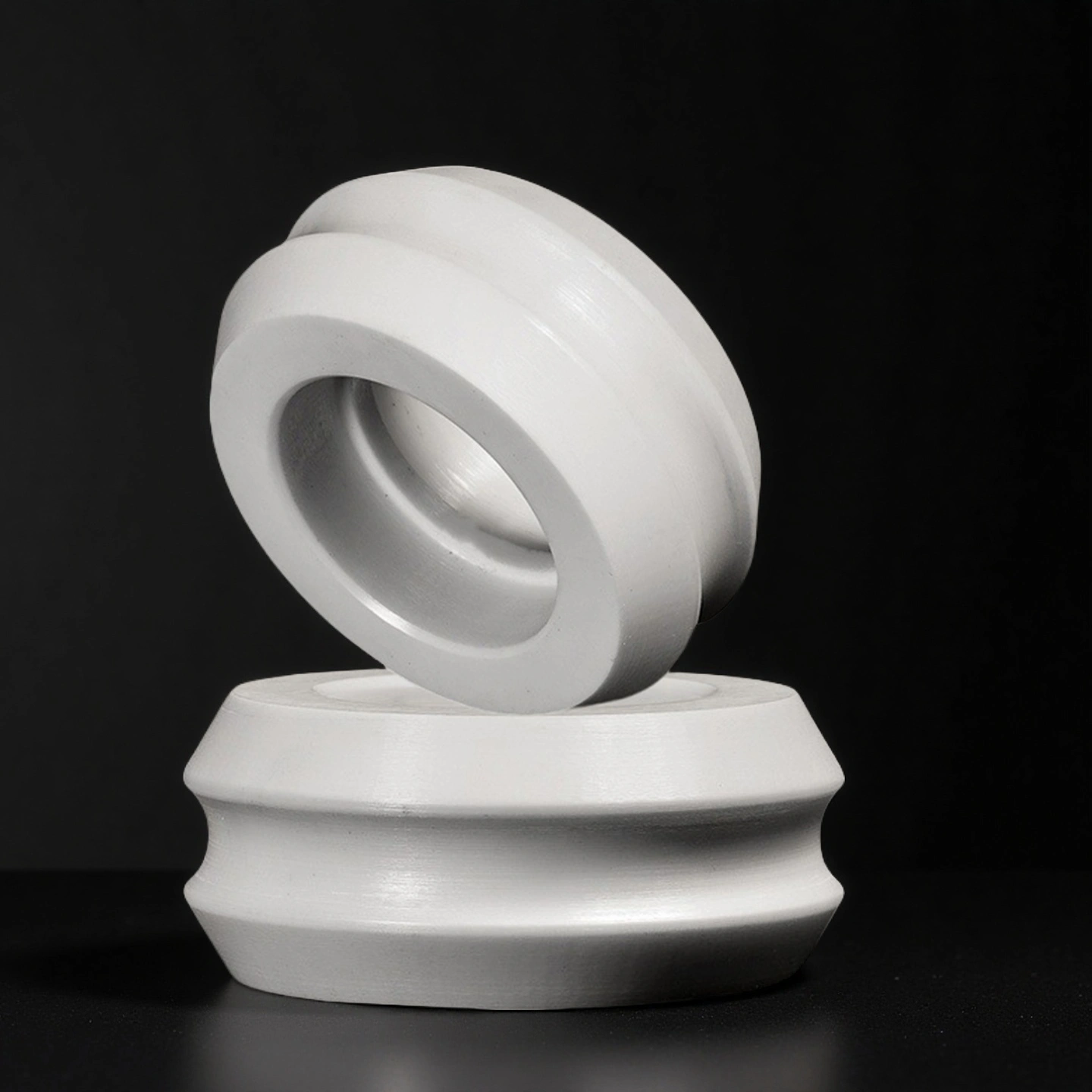
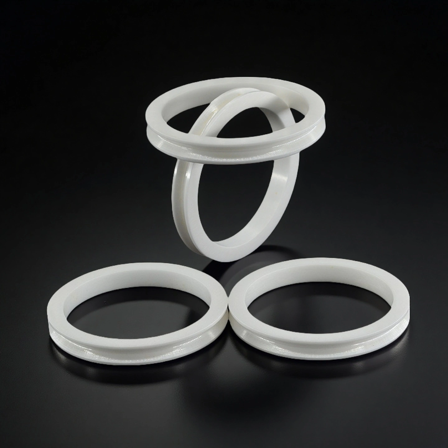
Groove Form: U, V, or flat grooves optimized for wire type
Edge Chamfering: Smooth entry/exit transition for fragile wires
Shoulder Height: Profile height adjusted for lateral alignment stability
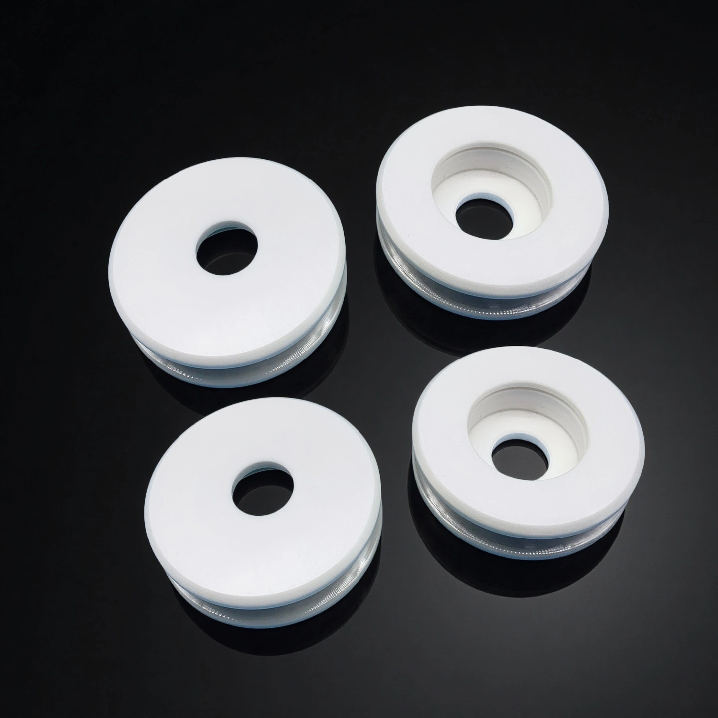
Mounting and Interface Adaptation
Interface dimensions are tailored to integrate directly with existing pulley systems or proprietary machines.
Bore Design: Customized bore fitting for keyed or plain shafts
Fixing Slots: Hole pattern modified for fixture compatibility
Assembly Fit: Press or slip fit based on drive configuration
Surface Engineering Options
Surface treatments can be applied to enhance contact performance or adapt to fluid exposure.
Polishing Level: Roughness controlled for low-friction contact
Coating Application: Optional film layers for oil or slurry resistance
Gloss Adjustment: Surface reflectivity matched for sensor feedback systems
Load and Stress Adaptation
Material microstructure and internal balance can be fine-tuned for specific stress environments.
Dynamic Balancing: Mass distribution optimized for high-RPM usage
Wall Thickness: Section profile tuned for axial compression limits
Stress Pathway: Stress lines engineered to prevent microfracture zones