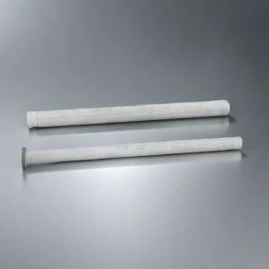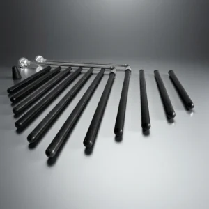
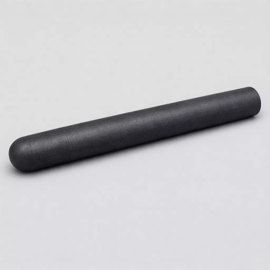
What Is a Silicon Carbide Protection Tube?
A silicon carbide protection tube is a ceramic sleeve used to protect thermocouples or temperature sensors from direct exposure to molten metal, corrosive gas, flame impact and rapid thermal cycling. In industrial furnaces and process heating systems, the tube acts as a stable barrier between the sensor and the working environment, helping maintain measurement accuracy and reduce premature sensor damage.
Compared with many oxide ceramic or metallic protection tubes, SiC protection tubes provide higher thermal conductivity, stronger wear resistance and improved stability in harsh thermal atmospheres. They are commonly selected for aluminum processing, heat-treatment furnaces, chemical process lines, burner ports and other high-temperature measurement positions.
Key Performance Features of Silicon Carbide Protection Tube
-
Dense Microstructure Stability
The SSiC matrix maintains structural density above 3.10–3.15 g/cm³, enabling resistance to gas penetration during long production cycles.
This high density supports measurement systems that require stable barrier protection in molten metal environments. -
Thermal Conductivity Efficiency
Heat transfer is supported by conductivity values of 90–120 W/m·K, reducing thermal lag for temperature sensors.
This helps maintain accurate readings under variable furnace heating conditions. -
Thermal Expansion Control
The material’s coefficient of 3.6–4.1 × 10⁻⁶/K minimizes dimensional change under rapid heating.
This reduces shock-related failure during high-frequency thermal cycling. -
Extended Temperature Endurance
The tube operates at 1,600–1,650 °C in air, supporting measurement applications inside continuous casting lines.
In controlled gas atmospheres, stability extends up to 1,900 °C, allowing protection in advanced furnace systems. -
Corrosion Resistance to Industrial Gases
The covalent Si–C structure resists SO₂, H₂S, and nitride-forming gases common in chemical plants.
This reduces sensor degradation when exposed to fluorides, alkalis, or combustion by-products. -
Molten Metal Compatibility
The surface remains unwetted by molten aluminum, copper, and zinc, preventing chemical erosion during immersion.
Lifetimes in these environments often reach 5–10× that of oxide ceramics. -
Flexural Strength Reinforcement
Strength values above 350 MPa allow stable operation when inserted into high-velocity gas streams or mechanical guide ports.
This prevents breakage when the tube is used in long-span or unsupported configurations. -
Compressive Load Resistance
The material withstands compressive forces greater than 2,200 MPa, supporting weight-bearing furnace designs.
This ensures integrity when the tube functions as a support or protection barrier in heated zones. -
Thermal Cycling Stability
The microstructure tolerates gradients exceeding 600 °C/min without cracking.
This performance reduces replacement frequency in rapid-heating furnaces and high-throughput casting systems.
Technical Specifications of Silicon Carbide Protection Tube
ADCERAX® Silicon Carbide Protection Tube is engineered for use in high-temperature, corrosive, and mechanically demanding industrial systems, where stable thermal behavior, predictable structural strength, and long-term chemical resistance are essential for reliable operation.
| Property | Specification | What It Means for Application |
|---|---|---|
| Material Type | SSiC / RBSiC | Allows selection according to thermal shock, corrosion exposure and mechanical loading requirements. |
| Density | 3.10–3.15 g/cm³ | Higher density helps limit gas penetration and improves barrier stability in harsh atmospheres. |
| Apparent Porosity | <0.1% | Low porosity supports corrosion resistance and reduces infiltration from gas or molten media. |
| Hardness | HV > 2200 | Helps resist abrasion from particles, scale and high-velocity furnace flow. |
| Flexural Strength | >350 MPa | Supports stable operation in long or partially unsupported tube configurations. |
| Compressive Strength | >2200 MPa | Helps the tube resist mechanical loading during installation and high-temperature service. |
| Thermal Conductivity | 90–120 W/m·K | Supports faster heat transfer and more responsive thermocouple measurement. |
| Thermal Expansion Coefficient | 3.6–4.1 × 10⁻⁶/K | Reduces dimensional change during heating and cooling cycles. |
| Maximum Service Temperature in Air | 1600–1650 °C | Suitable for many high-temperature furnace and burner-zone measurement positions. |
| Maximum Service Temperature in Controlled Atmosphere | Up to 1900 °C | May support selected high-temperature systems when atmosphere and loading are properly reviewed. |
| Thermal Shock Resistance | Stable under rapid thermal gradients | Helps reduce cracking risk during repeated insertion, heating and cooling cycles. |
| Corrosion Resistance | SO₂, H₂S, alkali vapor, molten Al/Cu/Zn | Supports thermocouple protection in corrosive gas and non-ferrous metal environments. |
| Oxidation Resistance | High stability at elevated temperatures | Helps reduce surface degradation during long furnace campaigns. |
| Electrical Resistivity | High, non-conductive ceramic | Supports sensor isolation in many industrial measurement systems. |
| Microstructure | Fine-grain, high-density SiC matrix | Improves long-term barrier behavior and surface stability. |
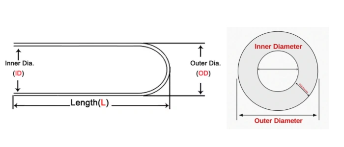
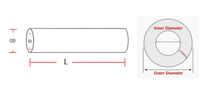
Dimensions of Silicon Carbide Protection Tube
The following silicon carbide protection tube sizes are reference options for preliminary selection. Final availability should be confirmed according to OD, ID, wall thickness, length, closed-end structure, mounting interface, sensor type and operating environment. Custom sizes can be reviewed from drawings, samples or application requirements.
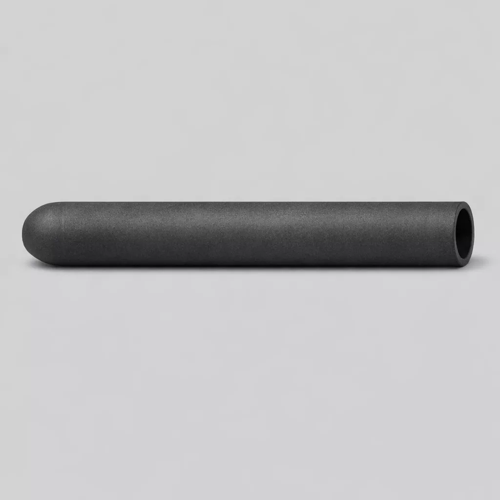
Type 1-SIC Protection Tube One End Closed
| Item | Outer Diameter (mm) | Inner Diameter (mm) | Length (mm) | SiC Content |
| AT-THG-G1001 | 20 | 10 | 500 | 92% |
| AT-THG-G1002 | 25 | 15 | 500 | 92% |
| AT-THG-G1003 | 30 | 20 | 500 | 92% |
| AT-THG-G1004 | 35 | 25 | 500 | 92% |
| AT-THG-G1005 | 40 | 30 | 500 | 92% |
| AT-THG-G1006 | 45 | 35 | 500 | 92% |
| AT-THG-G1007 | 50 | 40 | 500 | 92% |
| AT-THG-G1008 | 55 | 45 | 500 | 92% |
| AT-THG-G1009 | 60 | 50 | 500 | 92% |
| AT-THG-G1010 | 70 | 25 | 850 | 99% |
| AT-THG-G1011 | 70 | 30 | 850 | 99% |
| AT-THG-G1012 | 90 | 63 | 1000 | 99% |
| AT-THG-G1013 | 100 | 73 | 1250 | 99% |
| AT-THG-G1014 | 110 | 80 | 1200 | 99% |
| AT-THG-G1015 | 119 | 99 | 1050 | 99% |
| AT-THG-G1016 | 120 | 95 | 1200 | 99% |
| AT-THG-G1017 | 133 | 105 | 430 | 99% |
| AT-THG-G1018 | 155 | 130 | 1040 | 99% |
| AT-THG-G1019 | 168 | 140 | 430 | 99% |
| AT-THG-G1020 | 273 | 243 | 700 | 99% |
| AT-THG-G1021 | 280 | 230 | 1500 | 99% |
| AT-THG-G1022 | 20 | 8 | 1000 | 99% |
| AT-THG-G1023 | 25 | 13 | 1500 | 99% |
| AT-THG-G1024 | 30 | 18 | 1500 | 99% |
| AT-THG-G1025 | 35 | 23 | 1500 | 99% |
| AT-THG-G1026 | 40 | 26 | 1600 | 99% |
| AT-THG-G1027 | 50 | 35 | 1600 | 99% |
| AT-THG-G1028 | 60 | 40 | 1600 | 99% |
| AT-THG-G1029 | 20 | 10 | 500 | 99% |
| AT-THG-G1030 | 25 | 15 | 500 | 99% |
| AT-THG-G1031 | 30 | 20 | 500 | 99% |
| AT-THG-G1032 | 35 | 25 | 500 | 99% |
| AT-THG-G1033 | 40 | 30 | 500 | 99% |
| AT-THG-G1034 | 45 | 35 | 500 | 99% |
| AT-THG-G1035 | 50 | 40 | 500 | 99% |
| AT-THG-G1036 | 55 | 45 | 500 | 99% |
| AT-THG-G1037 | 60 | 50 | 500 | 99% |
| Item | Outer Diameter (mm) | Inner Diameter (mm) | Length (mm) | SiC Content |
| AT-THG-G2001 | 22 | 12 | 1000 | 99% |
| AT-THG-G2002 | 28 | 18 | 1000 | 99% |
| AT-THG-G2003 | 32 | 10 | 1000 | 99% |
| AT-THG-G2004 | 38 | 28 | 1000 | 99% |
| AT-THG-G2005 | 42 | 32 | 1000 | 99% |
| AT-THG-G2006 | 47 | 37 | 1000 | 99% |
| AT-THG-G2007 | 56 | 46 | 1000 | 99% |
| AT-THG-G2008 | 55 | 45 | 1000 | 99% |
| AT-THG-G2009 | 68 | 56 | 1000 | 99% |
| AT-THG-G2010 | 40 | 20 | 500 | 99% |
| AT-THG-G2011 | 30 | 18 | 500 | 99% |
| AT-THG-G2012 | 40 | 25 | 500 | 99% |
| AT-THG-G2013 | 30 | 18 | 400 | 99% |
| AT-THG-G2014 | 40 | 40 | 400 | 99% |
| AT-THG-G2015 | 70 | 25 | 850 | 99% |
| AT-THG-G2016 | 70 | 30 | 850 | 99% |
| AT-THG-G2017 | 90 | 63 | 1000 | 99% |
| AT-THG-G2018 | 105 | 70 | 1250 | 99% |
| AT-THG-G2019 | 104 | 82 | 1200 | 99% |
| AT-THG-G2020 | 120 | 100 | 1050 | 99% |
| AT-THG-G2021 | 115 | 90 | 1200 | 99% |
| AT-THG-G2022 | 128 | 90 | 430 | 99% |
| AT-THG-G2023 | 150 | 140 | 1040 | 99% |
| AT-THG-G2024 | 170 | 140 | 430 | 99% |
| AT-THG-G2025 | 270 | 240 | 700 | 99% |
| AT-THG-G2026 | 285 | 235 | 1500 | 99% |
| AT-THG-G2027 | 22 | 10 | 1000 | 99% |
| AT-THG-G2028 | 25 | 13 | 1500 | 99% |
| AT-THG-G2029 | 30 | 18 | 1500 | 99% |
| AT-THG-G2030 | 35 | 23 | 1500 | 99% |
| AT-THG-G2031 | 40 | 26 | 1600 | 99% |
| AT-THG-G2032 | 50 | 35 | 1600 | 99% |
| AT-THG-G2033 | 60 | 40 | 1600 | 99% |
![]() Download Silicon Carbide Protection Tube More Size
Download Silicon Carbide Protection Tube More Size
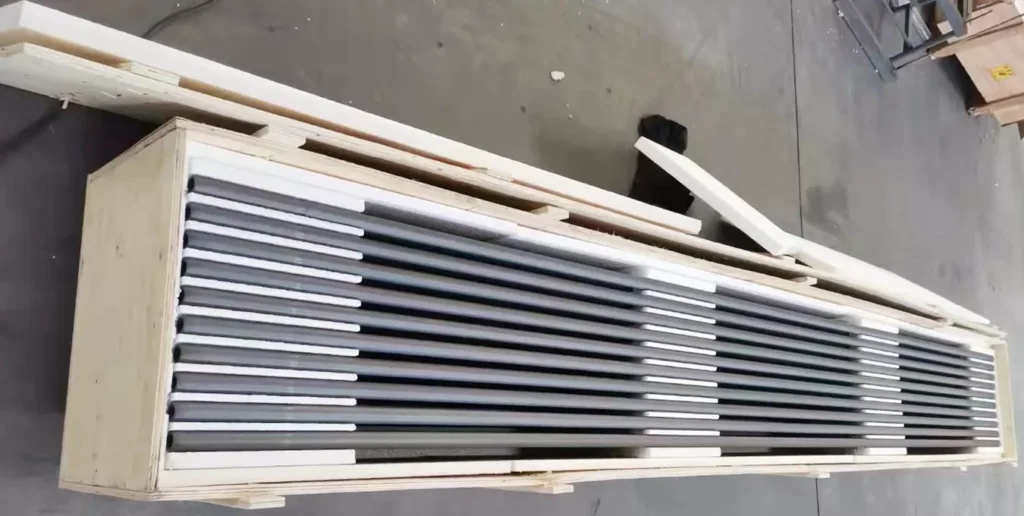
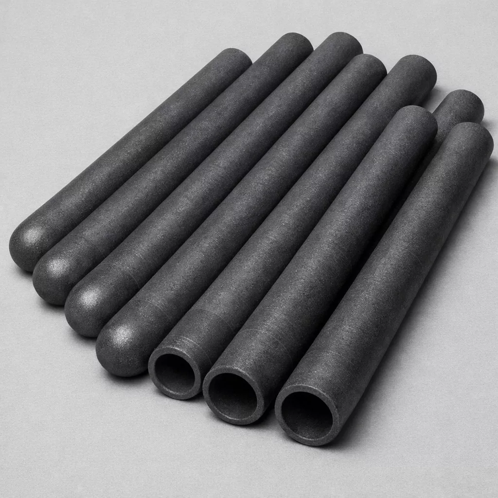
Packaging for Silicon Carbide Protection Tube
Silicon carbide protection tubes are separated with protective spacers and packed with cushioning materials to reduce vibration, edge contact and impact during transport. Long or closed-end tubes can be packed in reinforced cartons or wooden cases according to size, quantity and shipping route.