Alumina tube helium leak testing should be specified by test method, not by the phrase "helium leak tested" alone. ISO 20485 covers tracer-gas leak testing, while ASTM E493, E498, E499, and E1603 address different mass-spectrometer leak-test modes. For alumina tubes, the correct standard depends on whether the part is an open tube, closed-end tube, metallized tube, brazed assembly, or sealed feedthrough. The RFQ must define test direction, pressure condition, fixture, calibrated leak reference, acceptance leak rate, units, and report format.
Without those definitions, "helium leak tested" is a marketing claim rather than a receiving-inspection standard. This guide maps which standard applies to which alumina tube configuration, explains how to set an acceptance leak rate, separates ceramic body leakage from joint and fixture leakage, and closes with a complete RFQ and test report checklist.
The alumina ceramic tubes for custom dimensions, drawing-based submission, and vacuum-system applications covered in this guide include open furnace tubes, closed-end protection tubes, multi-bore insulators, and metallized ceramic tubes — each requiring a different helium leak test setup before the specification is executable.
Which standards apply to alumina tube helium leak testing
There is no single universal helium leak testing standard that applies to every alumina tube in the same way. The standard must be selected from the part's configuration and the test method needed to create a meaningful pressure boundary.
The Standards Map below identifies eight standards and references relevant to alumina tube helium leak testing:
| Standard / reference | Best use in alumina tube context | What it does not decide |
|---|---|---|
| ISO 20485:2017 | General tracer-gas leak testing method language | Final acceptance leak rate |
| ISO 20484:2017 | Leak-testing vocabulary and terminology alignment | Test fixture design |
| ASTM E432 | Method-selection guide for leak testing | Product-specific pass/fail value |
| ASTM E493 | Inside-out testing for sealed devices | Ordinary open-tube fixture leakage |
| ASTM E498 | Tracer probe mode with mass spectrometer or RGA | Universal alumina tube acceptance |
| ASTM E499 | Detector probe mode | Whether the leak is ceramic or fixture-related |
| ASTM E1603 | Hood mode leakage measurement | Drawing tolerance or ceramic grade |
| ASTM E908 | Reference leak calibration support | Application-specific leak-rate requirement |
Standards are method anchors; verify the latest edition, customer specification, and application-specific acceptance criteria before releasing a drawing or purchase order.
ISO 20485 is the broad international framework — it defines tracer-gas leak testing as the detection of a leak using a tracer gas and a tracer-gas-specific detector, typically with helium-4 mass spectrometer. ISO 20484 provides the vocabulary that aligns terminology between supplier and customer. ASTM E432 guides method selection, while E493, E498, E499, and E1603 each define a specific mass-spectrometer leak-test configuration. For alumina tubes, the test must be chosen from the part configuration: the same alumina material requires different test logic when it is an open tube inserted in a fixture versus a metallized tube brazed into a hermetic vacuum assembly.
ISO 20485 as the tracer-gas method umbrella
ISO 20485 establishes the technical language for specifying tracer-gas leak testing on a drawing or purchase order. Referencing "ISO 20485" in an RFQ signals the general method family — helium tracer gas, mass spectrometer or equivalent detector, defined pressure differential — without locking into a single fixture configuration. Additional specification fields (test direction, acceptance rate, fixture definition) must accompany any ISO reference.
ASTM method families for different test setups
The ASTM E-family standards separate leak-test modes by how helium is introduced and measured. E493 is designed for sealed devices tested with helium inside the part and the detector monitoring from outside. E498 uses a tracer probe directed at possible leak points from outside. E499 uses a detector probe to sense helium escaping from a part held at higher helium pressure. E1603 uses a hood or chamber enclosure to accumulate helium from a part and measure total leakage over time. Each mode has different sensitivity, setup complexity, and applicability to a given alumina tube geometry.
Why an open alumina tube needs a fixture-defined test
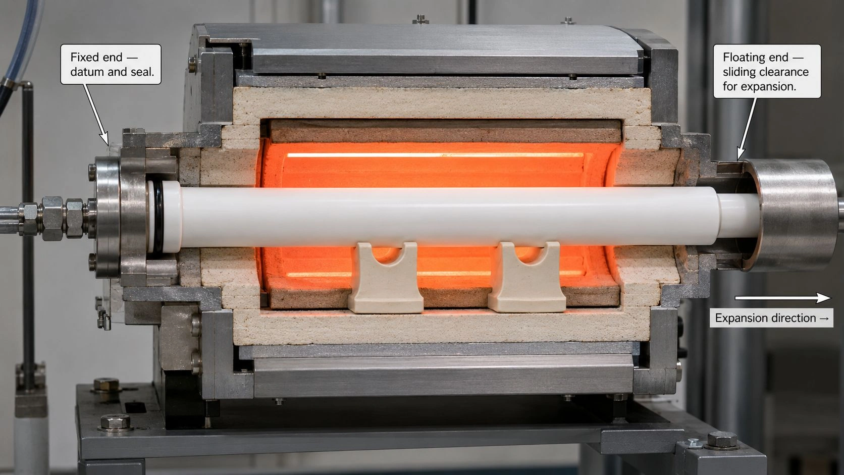
An open alumina tube has no inherent sealed boundary. Helium placed inside or outside the tube will flow freely unless the test fixture creates end seals that define the pressure differential. That means the test is actually measuring the combination of the tube wall, the fixture end seals, and all connections. Before accepting a "passed" result on an open tube, the fixture itself must be verified as leak-tight by a blank test without the ceramic tube inserted.
What leak rate and unit should be specified
Specifying an acceptance leak rate requires both a numeric value and a unit. Common units in helium leak testing are mbar·L/s, Pa·m³/s, atm·cc/s, and scc/s. These are not interchangeable without conversion — 1 mbar·L/s equals approximately 10⁻¹ Pa·m³/s and approximately 0.987 atm·cc/s — and drawing or purchase-order errors involving unit mismatch create acceptance disputes.
Published vacuum leak detection guidance confirms that standard helium conditions apply when the test object has vacuum inside, helium outside at atmospheric pressure, and the internal vacuum is below 1 mbar. That configuration is specific to sealed parts and must be explicitly defined when applied to alumina tube assemblies. For configurations that differ — pressurized helium inside, atmospheric outside, or partial helium mixtures — the test conditions must be stated and the resulting leak rate interpreted accordingly.
For context: published ADCERAX documentation on metallized alumina ceramic tubes states that properly brazed assemblies can achieve helium leak rates of ≤1×10⁻⁹ mbar·L/s under the defined test conditions for hermetic brazed components. That value applies to metallized and brazed assemblies, not to open alumina furnace tubes, thermocouple protection tubes, or laboratory ceramic sleeves tested in a fixture without a brazed hermetic interface. [CITE: Published ADCERAX metallized alumina ceramic tube data states that properly brazed tubes can achieve helium leak rates ≤1×10⁻⁹ mbar·L/s — a value that applies specifically to metallized/brazed hermetic assemblies under defined vacuum conditions, confirming that this acceptance rate cannot be assumed for open alumina tubes or fixture-mounted ceramic sleeves without equivalent sealing configuration.]
The acceptance leak rate for any alumina tube application must therefore be set by the application requirement — the tolerable gas exchange rate at operating conditions — not by a single catalog value.
Why "pass helium leak test" is incomplete
A specification that says only "pass helium leak test" fails to define what was tested, under what conditions, to what value, by what method, with what fixture, and against what calibrated reference. A supplier can technically satisfy that wording with any result that a detector registers as below its noise floor, which may not correspond to the application's actual requirement.
mbar·L/s vs Pa·m³/s vs atm·cc/s
For alumina tube specifications, mbar·L/s is the most common unit in European industrial vacuum practice; Pa·m³/s is the SI unit; atm·cc/s and scc/s appear frequently in US semiconductor and military specifications. Specify one unit on the drawing and confirm the supplier reports in the same unit. If conversion is needed, confirm the conversion factor is agreed in the purchase document.
Application-based acceptance rate, not universal acceptance rate
A high-vacuum component in a mass spectrometer or particle accelerator may require leak rates below 10⁻¹⁰ mbar·L/s. A furnace tube used to isolate a process atmosphere may only need a leak rate that prevents significant gas exchange at operating differential pressure. A vacuum-tight ceramic sleeve in an analytical instrument may have an intermediate requirement. The acceptance value must derive from the application's actual leakage tolerance, not from a generic "ceramic quality" assumption.
Do not confuse ceramic leakage, joint leakage, and fixture leakage
A helium signal during alumina tube testing does not automatically mean the ceramic wall is defective. Before attributing a test failure to the alumina body, three alternative leak paths must be ruled out.
Test fixture leakage is the most common source of false failures on open alumina tubes. The temporary O-ring seals, plugs, adhesives, or end caps used to create a closed test volume on an open tube may themselves introduce the measured helium signal. A blank fixture test — running the test setup without the tube — is the minimum verification step before a ceramic rejection is issued.
End seal, metallization, or braze joint leakage is the most relevant leak path in metallized alumina tubes and brazed assemblies. The ceramic-to-metal interface, metallized band, braze fillet, and thermal-cycle cracks at the joint may all introduce helium before the ceramic body is involved. Published guidance from vacuum leak detection references confirms that helium detectors can localize leaks faster than pressure-rise methods, but localization requires a deliberate test sequence — not a single-point measurement that cannot distinguish between the ceramic wall and the braze.
Helium background and false positives arise when residual helium in the test environment, contamination in the handling gloves, or prior use of helium in the same test fixture elevates the background reading above the intended detection threshold. Monitoring background before and after the part test is standard practice in calibrated leak testing.
The most practically important misdiagnosis in alumina tube helium leak testing is attributing a fixture or joint leak to the ceramic body. A blank fixture verification step and leak localization procedure should always precede a ceramic rejection decision.
Open tube fixture leakage vs ceramic wall defects
For open alumina tubes, the fixture is the primary variable. Different fixture designs will give different measured leak rates for the same ceramic tube. The drawing or test procedure must specify the fixture design, or the test result is not reproducible across suppliers.
Metallized and brazed joint leakage identification
For metallized tubes and brazed assemblies, the metallized alumina ceramic tube test should be designed to measure the assembly's hermetic performance at the joint — not the ceramic body in isolation. A test that measures only the ceramic wall of a metallized assembly may show a very low leak rate for the ceramic itself while the braze joint, if present, is not yet validated.
Method selection by alumina tube configuration
The Tube Configuration vs Test Method table below maps six common alumina tube types to their primary leak-path and practical test logic:
| Alumina tube type | Main leak path to control | Typical test logic | RFQ risk |
|---|---|---|---|
| Open straight tube | Fixture seal and tube wall | Fixture-defined vacuum or pressure boundary | Fixture leak mistaken for ceramic leak |
| Closed-end alumina tube | Closed end, wall, microcracks | Helium across wall / end with defined pressure differential | End defect missed by wrong setup |
| Multi-bore tube | Bore isolation and end sealing | Bore-by-bore fixture test if isolation matters | Cross-leakage not tested |
| Metallized alumina tube | Metal-ceramic interface | Hermetic assembly leak test | Ceramic body blamed for braze leak |
| Brazed feedthrough assembly | Braze, metal part, ceramic interface | Assembly-level helium leak test | Tube-only test not representative |
| Furnace protection tube | Atmosphere isolation, not hermetic package | Application-defined leak or pressure hold test | Over-specifying semiconductor package leak rates |
Test logic is application-specific; confirm fixture design, helium direction, pressure condition, and calibration standard before issuing a purchase order or acceptance report.
For open alumina furnace tubes, the test setup must create the sealed boundary that the ceramic wall does not inherently provide. For closed-end alumina protection tubes, the test applies helium across the closed end and wall, and the setup should specify where the helium is introduced and where it is monitored. For metallized tubes and brazed assemblies, ASTM E493-style inside-out testing or hood-mode accumulation may be appropriate depending on part scale and leak-rate sensitivity. ISO 20485 provides the tracer-gas method language applicable across all of these configurations.
The ceramic tubes and pipes category at ADCERAX covers alumina, SiC, zirconia, and BN formats — a useful cross-reference when evaluating whether alumina or an alternative ceramic material is appropriate for the sealing and leak-rate requirements of a specific application.
RFQ and test report checklist for alumina tube helium leak testing
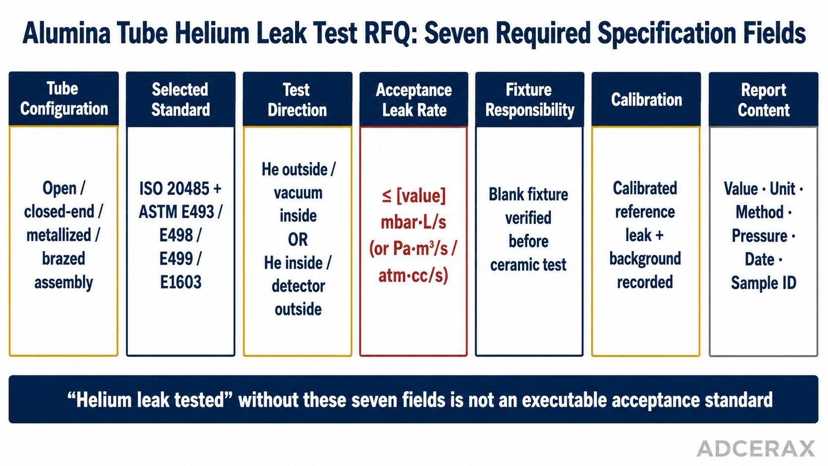
Alumina tube helium leak testing specification requires seven distinct fields — specifying only "helium leak tested" without these fields creates an acceptance criterion that cannot be executed.
The RFQ Fields table below provides minimum specification language for a purchasing document or drawing note:
| RFQ field | Why it matters | Recommended wording |
|---|---|---|
| Tube configuration | Determines method | "Open tube / closed-end tube / metallized tube / brazed assembly" |
| Selected standard | Controls test language | "Test per ISO 20485 and applicable ASTM method" |
| Test direction | Defines helium path | "Helium outside / vacuum inside" or "helium inside / detector outside" |
| Acceptance leak rate | Creates pass/fail criterion | "Acceptance ≤ [value] [unit] under stated test condition" |
| Fixture responsibility | Prevents false failure | "Supplier to verify blank fixture before part test" |
| Calibration | Ensures traceability | "Use calibrated reference leak; record background level" |
| Report content | Enables receiving inspection | "Report measured value, unit, method, pressure, date, sample ID" |
For test reports, require the supplier to include detector model or RGA method, calibration reference and traceability, background level at the start of the test, helium concentration if below atmospheric, pressure condition, measured leak rate, pass/fail result, sample identification, and test date. [CITE: Expert engineering guidance on helium leak testing specification confirms that a drawing or purchase order must define the standard, test method, direction, pressure, helium concentration, acceptance leak rate, unit, fixture responsibility, calibration requirement, and report fields — because the difference between "helium leak tested" and an executable acceptance standard is precisely these seven specification elements.]
For qualification of new alumina tube designs for vacuum or hermetic applications, a test-method review between the supplier and the customer before the first production run reduces the risk of acceptance disputes — especially when the fixture design, pressure condition, and calibrated reference leak have not been previously agreed.
Specifying helium leak testing for alumina tubes or metallized ceramic assemblies? Share your tube drawing, tube configuration, sealing method, operating pressure, target leak rate, preferred standard, and report requirements. ADCERAX engineers review the test condition and return a recommended alumina tube specification with method guidance and documentation plan; turnaround depends on inquiry complexity — no RFQ commitment required at this stage.
The alumina ceramic material and product family at ADCERAX supports custom tube geometry, tight dimensional tolerances, special purity grades, and drawing-based submissions — the starting point for any helium leak test specification that must be tied to a verified and repeatable part definition.
Frequently Asked Questions
Is there one standard for helium leak testing alumina tubes?
No. The correct standard depends on the tube configuration and the test method required to create a meaningful pressure boundary. ISO 20485 provides general tracer-gas method language applicable across configurations, while ASTM standards E493, E498, E499, and E1603 define specific mass-spectrometer leak-test modes. The drawing or purchase order must reference the applicable standard and define test direction, fixture, pressure, acceptance rate, and report format.
Can an open alumina tube be helium leak tested?
Yes, but only with a defined test fixture that creates a sealed boundary on both ends. Because an open tube has no inherent pressure boundary, the test result measures the combination of the tube wall and the fixture seals. The fixture must be verified as leak-tight by a blank test before the ceramic result is accepted as valid.
What helium leak rate should be specified for alumina tubes?
There is no universal acceptance value. The leak-rate target depends on the application: high-vacuum components may require rates below 10⁻¹⁰ mbar·L/s; furnace atmosphere isolation tubes may need only a pressure-hold style test; brazed hermetic assemblies typically require rates in the 10⁻⁹ to 10⁻¹⁰ mbar·L/s range. The acceptance value must be derived from the application's actual leakage tolerance and must include units and the specific test conditions under which it was measured.
What units are used for helium leak rate?
The most common units are mbar·L/s, Pa·m³/s, atm·cc/s, and scc/s. These are related by defined conversion factors but should not be mixed without explicit conversion. The drawing and test report should agree on one unit, or the purchase document should provide the agreed conversion basis to prevent acceptance disputes.
Does a helium leak failure mean the alumina ceramic is porous or defective?
Not necessarily. The helium signal may originate from the test fixture, O-ring end seals, metallization layer, braze joint, or residual background helium rather than from porosity or cracks in the ceramic body. A blank fixture test and leak localization procedure should be performed before a ceramic rejection decision is made.
What should a supplier report after helium leak testing an alumina tube?
The report should include the test standard and method, detector model or RGA mode, calibration reference and traceability, background level at the start of the test, pressure condition, helium concentration if below atmospheric, measured leak rate with unit, pass/fail result against the stated acceptance criterion, sample identification, and test date. These fields together make the report usable for receiving inspection, traceability records, and qualification documentation.