SiC tubes can resist creep well at 1400°C when the applied stress, support span, tube diameter, wall thickness, atmosphere, and SiC grade are correctly matched — but "rated to 1400°C" does not automatically mean "load-bearing without deformation." Creep is time-dependent strain under sustained temperature and stress. A long horizontal tube, a point-loaded fixture, an excessive unsupported span, or a corrosive atmosphere can still cause sag, ovality, or delayed cracking even when the temperature specification is formally met. The RFQ must define load, span, temperature profile, and verification method before any grade recommendation can be confirmed.
That distinction — between a temperature limit and a load-bearing limit — is the engineering boundary this guide unpacks.
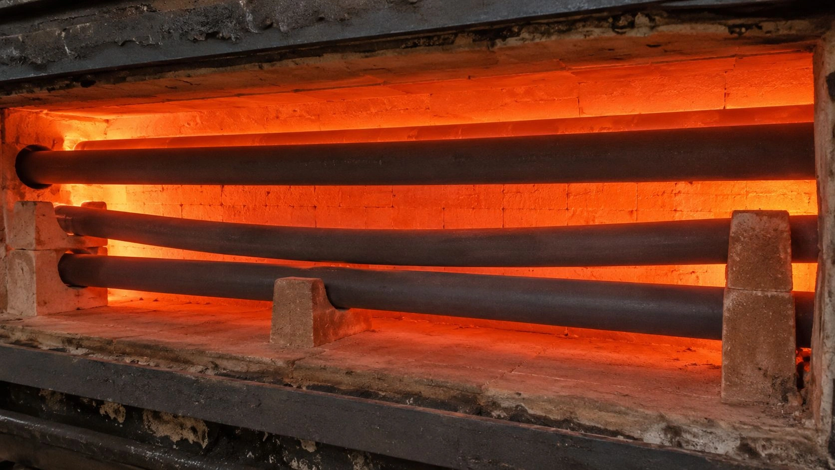
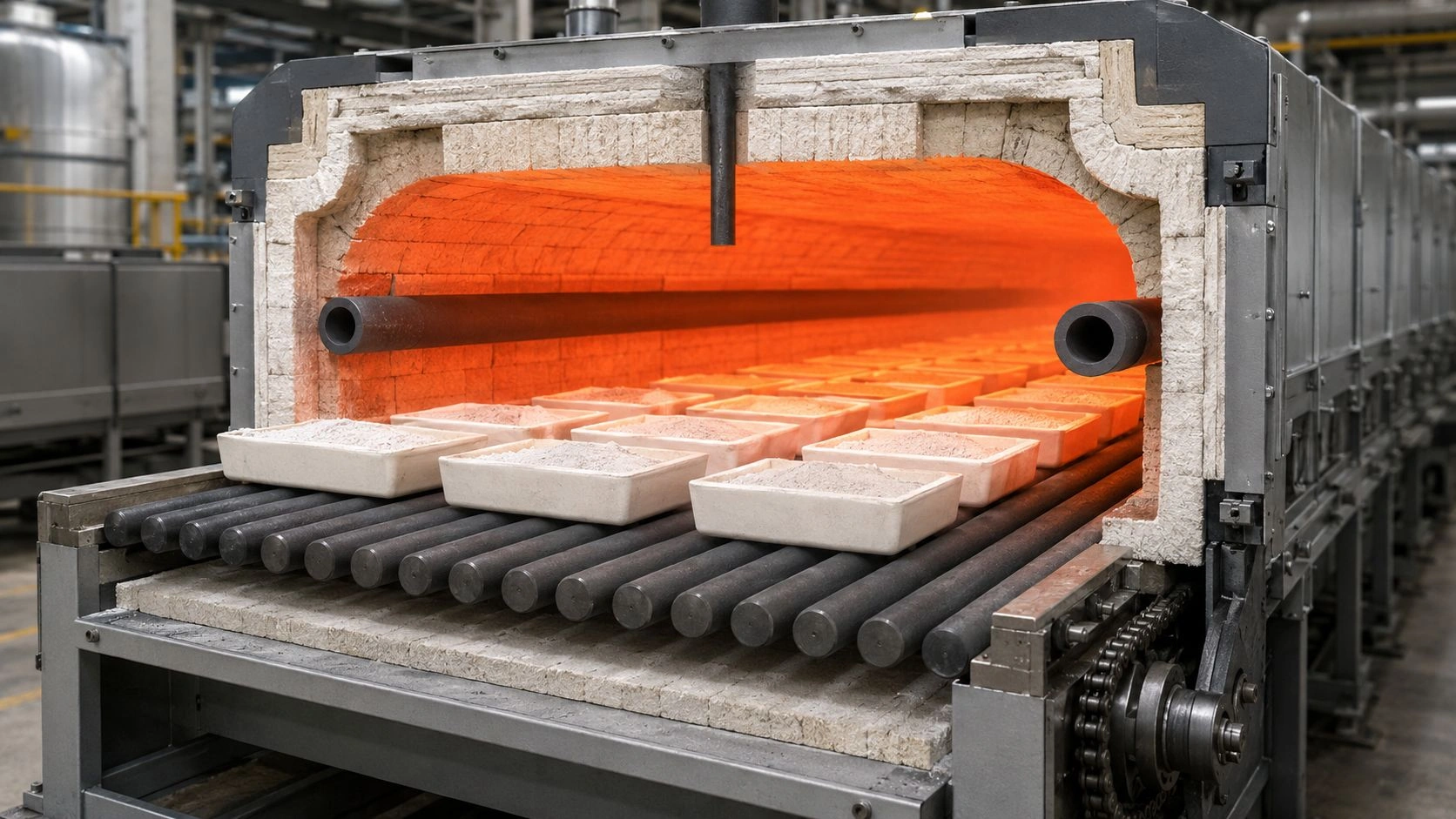
A long horizontal SiC tube under sustained load at 1400°C faces a different engineering question than a short vertical protection tube at the same temperature — support span, bending stress, and time at temperature all contribute to creep risk.
This article is part of ADCERAX's coverage of silicon carbide tubes for high-temperature furnace, radiation, and heat-exchange applications, where load-bearing behavior under sustained thermal conditions is a central specification variable.
Does a SiC tube creep at 1400°C under load?
The short answer is: SiC has strong high-temperature dimensional stability, but creep risk is not zero by definition at 1400°C under sustained load. Creep means time-dependent strain under simultaneous temperature and stress. A tube may survive a short high-temperature exposure without measurable deformation and still show gradual sag or ovality during continuous furnace service if bending stress is too high.
ASTM C1291 defines elevated-temperature tensile creep testing for advanced monolithic ceramics, measuring creep strain, creep strain rate, and time-to-failure across 1073 to 2073 K. At 1400°C — which equals 1673 K — a SiC tube is inside that testing range, confirming that creep is a real and measurable phenomenon in advanced ceramics at this temperature under load. NIST's Ceramics Data Portal describes sintered silicon carbide as a structural ceramic used in heat exchangers and aggressive high-temperature environments — but the material characterization is a starting point, not a load-approval.
The practical consequence is that the same SiC grade can produce very different outcomes in service depending on tube orientation, span, load, and duration:
Creep is not the same as melting or short-term failure
A tube that has excellent high-temperature strength in a short-duration flexural test can still deform over weeks or months under sustained load at the same temperature. Creep is a slow process — it accumulates strain incrementally. The failure mode is not catastrophic fracture but gradual dimensional change that eventually makes the tube unusable, causes load redistribution onto supports, or creates ovality that affects process flow or sealing.
Why 1400°C must be paired with stress and time
Maximum service temperature is a thermal property. Creep resistance at that temperature is a mechanical property under sustained load conditions. The two properties are related but not equivalent. A supplier who provides maximum operating temperature without also providing bending stress limit, allowable span, or long-duration load data has answered only half the specification question.
Why horizontal tubes are higher-risk than vertical protection tubes
A short vertical thermocouple protection tube under no mechanical load other than its own weight carries essentially no bending stress. A long horizontal kiln roller, radiant tube, or heat-exchange tube carries distributed self-weight plus process load — creating a bending moment along the span that is absent in the vertical case. Creep risk scales with bending stress, so tube orientation and span are first-order design variables, not secondary installation details.
What controls SiC tube creep risk at 1400°C?
Five engineering variables control creep risk in practical SiC tube applications. The risk cannot be assessed from temperature rating alone.
[CITE: ASTM C1211, which covers elevated-temperature flexural strength of advanced ceramics, explicitly notes that measured strength can be rate-dependent because of creep, stress corrosion, or slow crack growth — confirming that high-temperature load-bearing performance in silicon carbide ceramics cannot be inferred solely from room-temperature strength values or nominal temperature ratings, and must be evaluated under the actual stress and time conditions of the application.]
The Creep-Risk Matrix below maps each variable to its lower-risk and higher-risk condition:
| Variable | Lower-risk condition | Higher-risk condition | What to verify |
|---|---|---|---|
| Temperature exposure | Short or moderate hold time | Long continuous hold at 1400°C | Time-at-temperature profile |
| Load type | Low distributed load | High point load or heavy internal tray | Load map and support contact |
| Tube orientation | Vertical protection tube | Long horizontal tube | Span and bending stress |
| Support spacing | Multiple distributed supports | Long unsupported span | Furnace layout drawing |
| Wall geometry | Wall matched to stiffness and gradient | Thin wall with high bending load | OD/ID/wall calculation |
| SiC grade | Grade matched to load and atmosphere | Grade selected only by price or availability | SSiC/RBSiC/NSiC/ReSiC data |
| Atmosphere | Clean air or known controlled gas | Alkali, water vapor, reducing/corrosive gases | Compatibility review |
Values indicative; verify per supplier-specific SiC grade data, ASTM C1291/C1211 where applicable, and application trials.
Applied bending stress and support span
In a horizontal tube under distributed load, the maximum bending stress scales with the square of the unsupported span. Halving the support spacing reduces peak bending stress by a factor of four — a much larger improvement than upgrading material grade for a given application. This is why support layout should be resolved before grade selection in most horizontal-tube applications.
Wall thickness, OD/ID, and stiffness
A larger outer diameter improves the section modulus and increases stiffness, but wall thickness must be matched to the thermal gradient through the wall as well as the bending load. An excessively thick wall in a high-gradient environment can create tensile stress on the outer surface during rapid heating. The balance between stiffness and thermal stress is tube-geometry-specific.
SiC grade and residual phase boundary
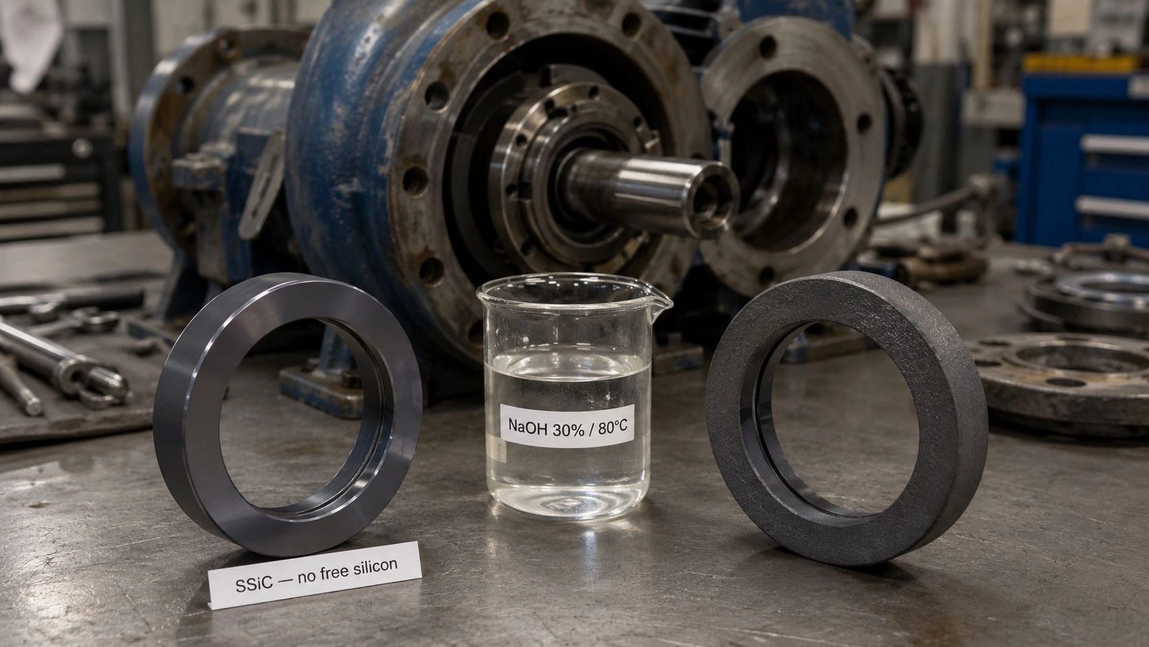
Sintered SiC (SSiC), reaction-bonded SiC (RBSiC/SiSiC), recrystallized SiC (ReSiC), and nitride-bonded SiC (NSiC) differ in porosity, residual phase, density, and high-temperature mechanical behavior. A recrystallized SiC grade may have higher open porosity and a different creep boundary than a dense sintered grade at the same temperature. Grade selection should be driven by high-temperature load data specific to the grade, not by general SiC brand or maximum temperature alone.
Atmosphere and oxidation/corrosion effects
SiC forms a protective SiO₂ surface layer in oxidizing atmospheres that stabilizes the surface at moderate temperature. In the presence of water vapor, alkali vapors, reducing gases, or corrosive process chemicals, that protective layer can be disrupted or consumed — degrading surface strength and potentially accelerating creep or slow crack growth. Atmosphere specification is part of the grade-selection decision, not a secondary note.
Do not misdiagnose creep when the real cause is support, thermal shock, or atmosphere
A bent or cracked SiC tube is not necessarily a creep failure. Misidentifying the failure mode leads to replacing the material grade without fixing the root cause — and the new tube will fail the same way.
True creep usually appears as gradual sag, ovality, or permanent dimensional change that accumulates over sustained temperature and load. The deformation is distributed across the span and correlates with the time-at-temperature record. Other failure modes produce different patterns:
Gradual sag vs sudden thermal shock crack. Thermal shock failure is typically sudden, occurring during rapid heating or cooling rather than after long hold time. The crack pattern often shows branching from a surface origin and is associated with temperature-change events rather than long service time. If the tube survived weeks or months and then bent rather than broke, creep or overload is more likely than thermal shock.
Support-point cracks vs whole-span creep. A crack near a support or end connection is often caused by localized stress concentration at the contact point rather than distributed creep along the span. Point loading, rigid clamping, or thermal expansion mismatch at the tube ends can all produce local damage that is unrelated to creep mechanics. Published research on SiC-related ceramics at elevated temperature has distinguished between slow crack growth and creep-damage mechanisms, noting that applied stress level and material grade both determine which failure mode dominates.
Oxidation/corrosion weakening vs load-driven creep. Surface roughening, localized pitting, or surface recession in aggressive atmospheres weakens the tube cross-section over time — reducing effective wall thickness and increasing local bending stress. This mechanism can accelerate apparent creep deformation without the underlying material experiencing true creep in the classical sense.
Wrong SiC grade vs wrong tube layout. A tube that sags progressively after installation may have the wrong support spacing rather than the wrong material grade. Before specifying a denser, stiffer, or more expensive SiC grade, confirming the support layout and load distribution is the correct first diagnostic step.
The Creep vs Similar Failures table below summarizes the diagnostic questions:
| Observed symptom | Likely creep signal | Could be something else | Diagnostic question |
|---|---|---|---|
| Gradual sag across span | Yes | High load + inadequate support | Did deformation increase over long hold time? |
| Crack near support | Not necessarily | Point loading or thermal gradient | Is damage localized at contact point? |
| Sudden fracture after cooling | Usually no | Thermal shock | Did failure occur during rapid cool-down? |
| Surface roughening | Not primary creep | Oxidation/corrosion environment | What atmosphere and vapor species were present? |
| Ovality after long service | Possible | Fixture compression or uneven heating | Is ovality aligned with load direction? |
| End crack | Not primary creep | Axial restraint | Were both ends rigidly fixed? |
Diagnostic questions should be answered from service records and inspection before any material change is specified.
Design rules to reduce SiC tube creep deformation at 1400°C
After confirming that creep — rather than thermal shock, point loading, or atmospheric degradation — is the dominant concern, the design response follows a clear priority order.
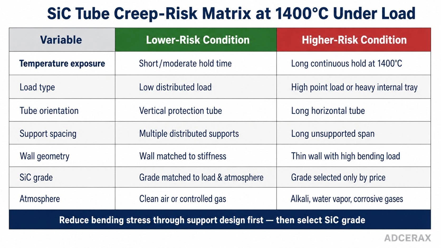
Creep risk in SiC tubes is controlled by seven engineering variables — bending stress and support span are usually the highest-leverage design parameters before material grade is changed.
Reduce unsupported span before upgrading material grade. For a given tube geometry and load, shorter support spacing reduces bending stress quadratically. This is almost always a lower-cost intervention than switching to a denser or higher-purity SiC grade, and it can be implemented without changing the tube itself.
Use distributed contact instead of point loading. Support cradles, rollers with broad contact area, or refractory saddles distribute the tube's weight over a larger surface rather than concentrating load at isolated contact points. This reduces local stress peaks that can initiate creep or cracking at the support location.
Match wall thickness to thermal gradient and stiffness requirements. Thicker walls increase section modulus and stiffness but also slow temperature equalization through the wall. For tubes that cycle frequently, wall thickness is a compromise between stiffness and thermal shock resistance. For steady-state long-duration service, thicker walls generally reduce creep risk if the thermal gradient permits.
Confirm grade against load and atmosphere, not just temperature. The silicon carbide ceramic material grades — SSiC, RBSiC, NSiC, and ReSiC — differ in density, porosity, residual phase, and high-temperature mechanical behavior. SSiC is typically the densest and most chemically resistant grade; RBSiC/SiSiC retains a silicon phase that limits service temperature in some conditions; ReSiC has higher porosity but excellent thermal shock resistance; NSiC has a nitride bonding phase that affects corrosion behavior. Grade selection should be confirmed against supplier-specific elevated-temperature data, not nominal maximum temperature.
Avoid rigid end constraints that add axial thermal stress. When a tube is fixed at both ends and heated, axial thermal expansion creates compressive stress along the tube length. Combined with bending, this can significantly increase effective stress at critical locations. Slip-fit end constraints or expansion-accommodating support designs reduce this risk.
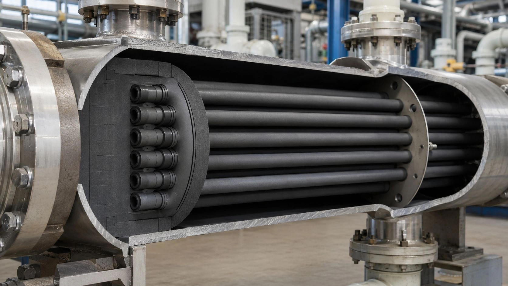
The silicon carbide tube product range includes protection tubes, cold-air pipes, radiation tubes, and heat-exchange tubes with OD options and maximum length capabilities — the geometry and span review for any specific application should be done from the actual tube drawing rather than catalog values.
RFQ checklist for 1400°C load-bearing SiC tubes
A complete RFQ for a load-bearing SiC tube at 1400°C must provide the operating conditions that determine stress — not just the temperature. A supplier who receives a temperature specification without load, span, and orientation data cannot confirm whether the tube geometry and grade are appropriate for the duty.
[CITE: Engineering guidance on creep-resistant ceramic tube specification confirms the practical sequencing rule: reduce bending stress first through support spacing, load distribution, and wall geometry before upgrading SiC grade — because grade selection alone cannot compensate for a stress condition that exceeds the material's creep boundary, and because ASTM C1291 creep data or ASTM C1211 elevated-temperature flexural data are the appropriate verification anchors when load-bearing qualification is required at temperatures above 1300°C.]
| RFQ field | Why it matters | Recommended wording |
|---|---|---|
| SiC grade | Controls high-temperature behavior | "Specify SSiC/RBSiC/NSiC/ReSiC route" |
| OD/ID/wall/length | Defines stiffness and fit | "Confirm dimensions, tolerance, and straightness" |
| Load condition | Drives creep risk | "Provide mass, contact area, and load distribution" |
| Support spacing | Controls bending stress | "Review unsupported span and support layout" |
| Temperature profile | Controls creep exposure | "State continuous and peak temperature, hold time" |
| Atmosphere | Affects oxidation/corrosion | "State air, inert, reducing, vapor, or process gas" |
| Acceptable sag | Defines pass/fail | "Define maximum allowable deflection after service" |
| Test evidence | Supports qualification | "Provide high-temp strength/creep data if available" |
RFQ fields are the minimum for a load-bearing SiC tube inquiry; add application-specific requirements as needed.
For critical horizontal tubes — radiant tubes, kiln rollers, heat-exchange tubes, or long protection tubes over 600 mm — the supplier should review the full assembly drawing including support position, end constraint, tube orientation, and load distribution, rather than treating the tube as a standalone product decision. When qualification data is required, ASTM C1291 for elevated-temperature tensile creep or ASTM C1211 for elevated-temperature flexural behavior provide the appropriate test frameworks.
The ceramic tube and pipe options across SiC, alumina, zirconia, and BN illustrate the same principle: material temperature rating is a starting point, and load-bearing specification requires the full operating envelope.
Evaluating SiC tubes for 1400°C load-bearing service? Share your tube drawing, load mass, support spacing, furnace orientation, atmosphere, hold time, and allowable sag. ADCERAX engineers review whether SSiC, RBSiC, NSiC, ReSiC, or another ceramic tube route fits the application; turnaround depends on inquiry complexity — no RFQ commitment required at this stage.
Frequently Asked Questions
Does SiC creep at 1400°C?
SiC can show strong creep resistance at 1400°C, but creep is not zero by definition. Creep depends on applied stress, time under load, tube geometry, support spacing, SiC grade, and atmosphere. ASTM C1291 defines elevated-temperature tensile creep testing for advanced ceramics across the 1073–2073 K range, confirming that 1400°C is inside the zone where creep must be evaluated under load rather than assumed absent.
Is 1400°C safe for all SiC tubes under load?
No. A tube temperature-rated for 1400°C may still deform if it is long, horizontal, point-loaded, thin-walled, exposed to a degrading atmosphere, or held at temperature under significant load for extended periods. Temperature rating and load-bearing rating are related but not equivalent specifications.
What is the most important design factor for reducing creep?
Bending stress is usually the dominant factor for horizontal tubes. Support spacing is the highest-leverage design parameter because bending stress scales with the square of the unsupported span — halving the span reduces peak stress by a factor of four. Load distribution, wall thickness, and grade selection follow once support spacing is optimized.
How is creep different from thermal shock failure?
Creep is gradual time-dependent deformation that accumulates under sustained temperature and load, typically becoming visible over weeks or months of continuous service. Thermal shock is typically sudden cracking caused by rapid temperature gradients during heating or cooling cycles. Both can occur in SiC tubes, but they require different design responses and should not be confused in failure diagnosis.
Which testing standard applies to ceramic tube creep?
ASTM C1291 covers elevated-temperature tensile creep strain, creep strain rate, and creep time-to-failure for advanced monolithic ceramics. ASTM C1211 is relevant for elevated-temperature flexural strength where rate-dependent effects from creep, stress corrosion, or slow crack growth may influence results. For load-bearing SiC tubes, requesting supplier data aligned with these standards is the appropriate verification step.
What information should I send to a supplier for 1400°C load-bearing SiC tubes?
Send the tube drawing with OD, ID, wall thickness, and length; the furnace orientation (horizontal, vertical, or angled); the continuous and peak temperature and hold time; the load mass and how it contacts the tube; the support spacing and layout; the furnace atmosphere and any process gases; the thermal cycling rate; the end constraint type; and the maximum acceptable sag or dimensional change after service.