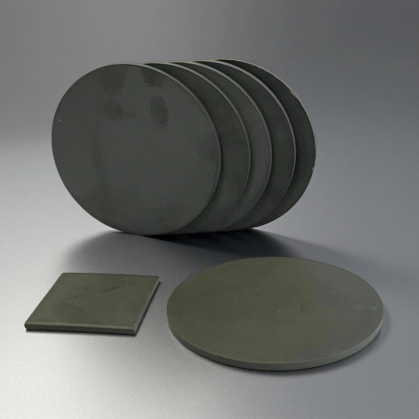
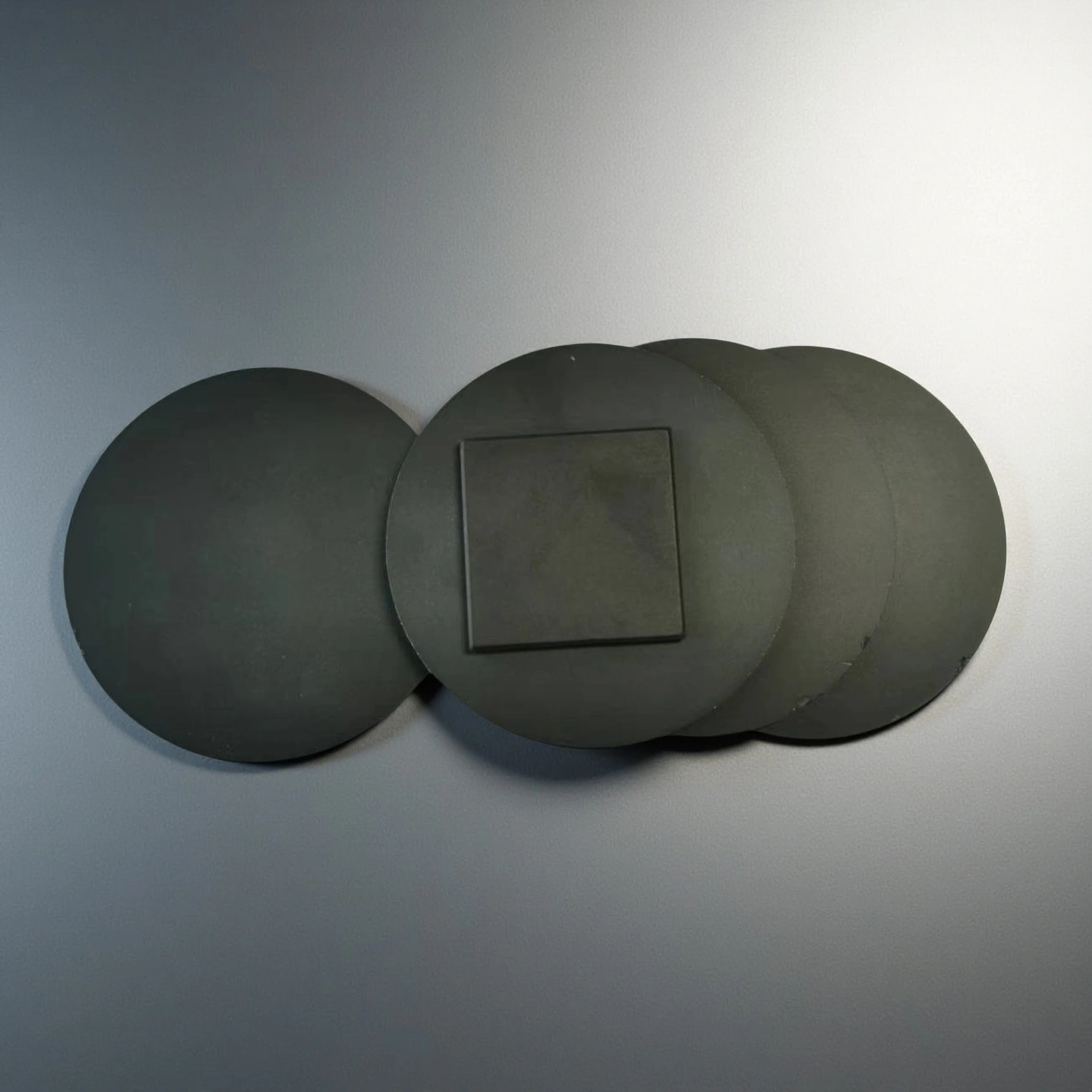
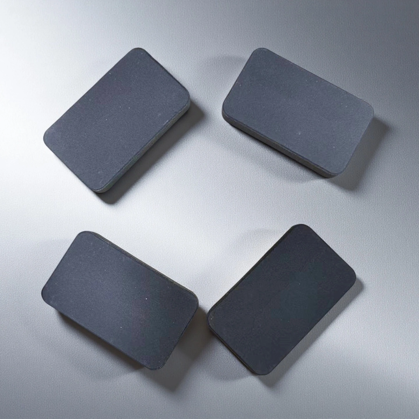
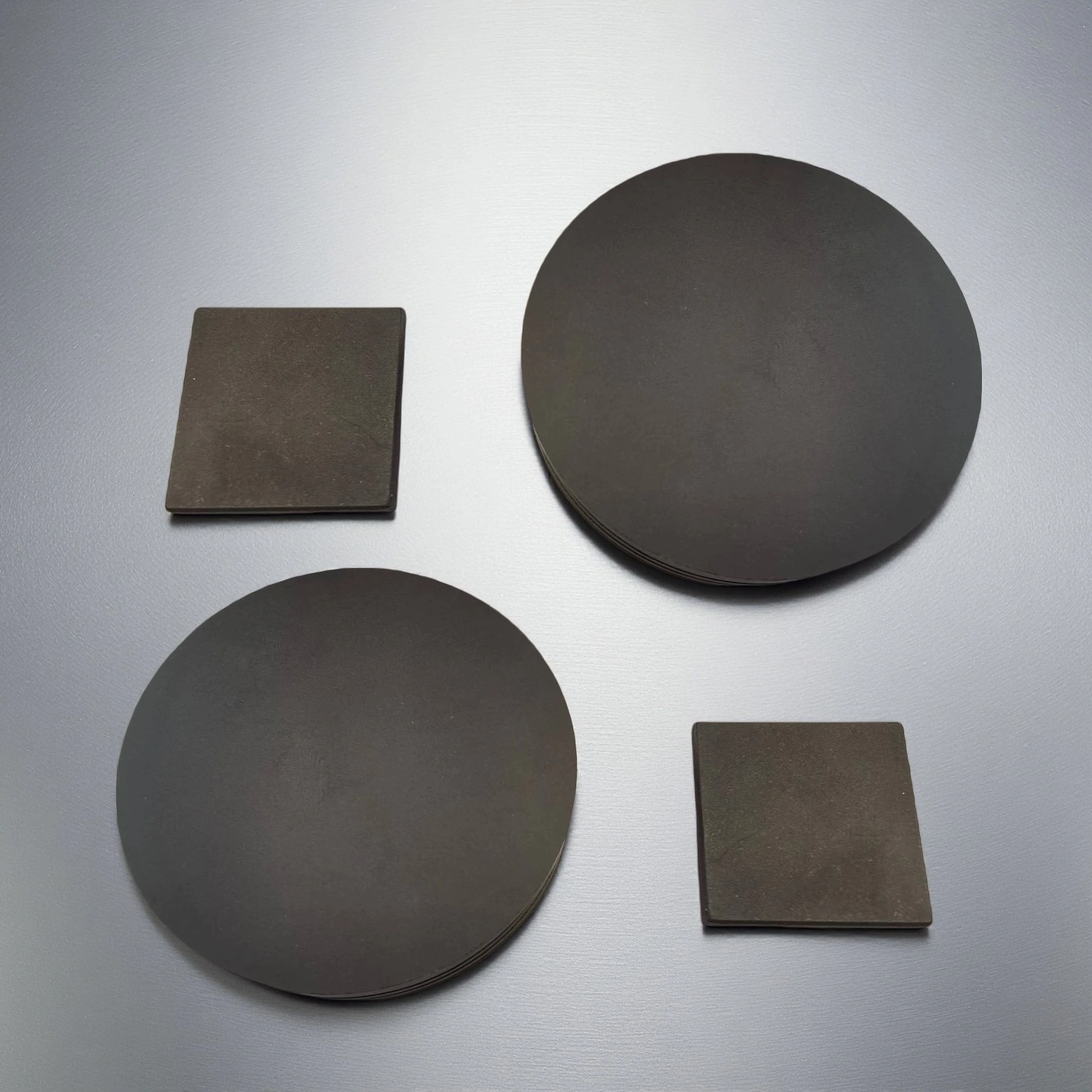
Black Alumina Substrate is a specialized flat sheet or plate made from aluminum oxide (Al₂O₃) ceramic that has been colored black during its manufacturing process. Its primary purpose is to serve as a foundational component in electronic devices, where it simultaneously provides electrical insulation, thermal conductivity (to dissipate heat), and light absorption (to protect sensitive components).
Black Alumina Ceramic Substrate Advantages
- Light-absorbing, low-reflection surface — the doped black colour gives an opaque, low-reflection surface that helps shield light-sensitive components from stray light, which can help reduce optical noise in sensor and photodiode packages (light-shielding level confirmed by sample test).
- High electrical insulation — alumina provides high dielectric strength (typically >=15 kV/mm, thickness-dependent) and high volume resistivity, supporting insulation in high-density and higher-voltage packages.
- Alumina-grade thermal and thermal stability — black alumina conducts heat at typical alumina levels (about 11-24 W/m·K by grade, not AlN-level); together with a low CTE this helps manage heat and keep dimensional stability under thermal cycling, depending on grade and design.
- Dimensional precision for assembly — a low CTE and controlled warpage help the substrate keep flatness and consistent bond-line thickness during automated assembly; actual warpage depends on size, thickness and process.
Black Alumina Substrate Properties
|
Property |
Unit |
96% Al₂O₃ |
99% Al₂O₃ |
99.5% Al₂O₃ |
99.6% Al₂O₃ |
99.7% Al₂O₃ |
99.8% Al₂O₃ |
99.9% Al₂O₃ |
99.99% Al₂O₃ |
|
Alumina content |
% |
96 |
99 |
99.5 |
99.6 |
99.7 |
99.8 |
99.9 |
99.99 |
|
Density |
g/cm³ |
3.6-3.75 |
3.83 |
3.89 |
3.91 |
3.92 |
3.93 |
3.94 |
3.98 |
|
Color |
– |
white |
Ivory |
Ivory |
Ivory |
Ivory |
Ivory |
Ivory |
Ivory |
|
Water absorption |
% |
0 |
0 |
– |
0 |
0 |
0 |
0 |
0 |
|
Young’s modulus (Elastic modulus) |
GPa |
300 |
350 |
375 |
356 |
357 |
358 |
359 |
362 |
|
Shear modulus |
GPa |
– |
– |
152 |
– |
– |
– |
– |
– |
|
Bulk modulus |
GPa |
– |
– |
228 |
– |
– |
– |
– |
– |
|
Poisson’s ratio |
– |
– |
– |
0.22 |
– |
– |
– |
– |
– |
|
Compressive strength |
MPa |
1910 |
2210 |
2500 |
2552 |
2554 |
2556 |
2558 |
2570 |
|
Flexural strength |
MPa |
260 |
300 |
340 |
345 |
346 |
347 |
348 |
365 |
|
Fracture toughness |
MPa·m¹ᐟ² |
– |
– |
4 |
– |
– |
– |
– |
– |
|
Hardness |
GPa |
14.5 |
17 |
17 |
23 |
24 |
25 |
26 |
30 |
|
Thermal conductivity |
W/m·K |
20 |
31 |
31 |
31-33 |
31-33 |
31-33 |
31-35 |
31-35 |
|
Thermal shock resistance ΔT |
°C |
– |
– |
– |
222 |
223 |
224 |
225 |
228 |
|
Maximum use temperature (no load) |
°C |
1450 |
1680 |
≤1750 |
1755 |
1760 |
1765 |
1770 |
1800 |
|
Coefficient of thermal expansion |
10⁻⁶/°C |
7.6 |
7.6 |
7.6 |
7.6 |
7.5 |
7.5 |
7.4 |
7.4 |
|
Volume resistivity |
Ω·cm |
>1×10¹⁴ |
>1×10¹⁴ |
>1×10¹⁴ |
>1×10¹⁴ |
>1×10¹⁴ |
>1×10¹⁴ |
>1×10¹⁴ |
>1×10¹⁴ |
|
Dielectric constant (relative permittivity) |
– |
9.2 |
9.5 |
9.8 |
9.83 |
9.84 |
9.85 |
9.86 |
9.92 |
|
Dielectric strength |
kV/mm |
15 |
19 |
16.9 |
23.2 |
23.4 |
23.6 |
23.8 |
24 |
|
Dissipation factor (loss factor @ 1 kHz) |
– |
– |
– |
0.0002 |
– |
– |
– |
– |
– |
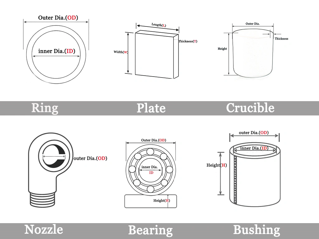
Black Alumina Ceramic Substrate Specifications
| Model |
Length x Width |
Thickness |
Aluminum Oxide Content (%) |
| AT-AO-J001 |
1-100 |
0.3-10 |
96/99 |
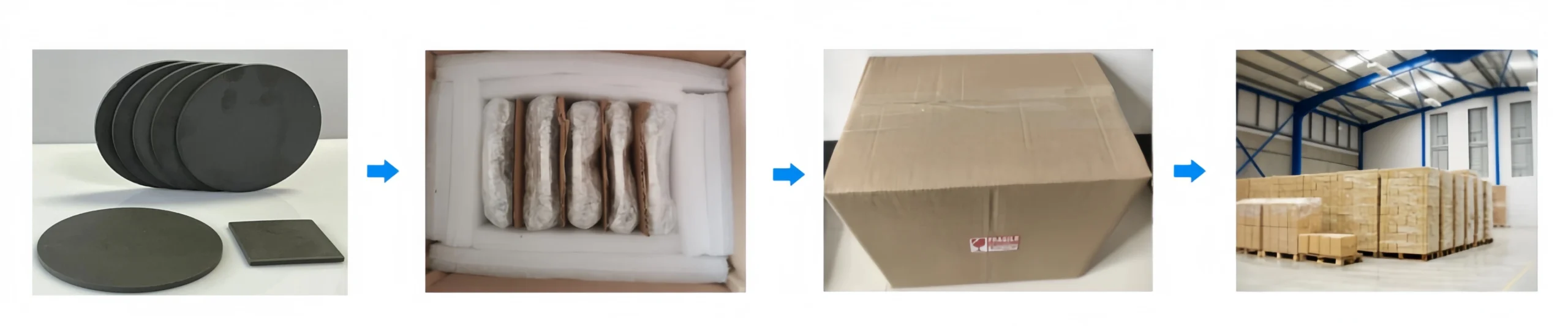
Black Alumina Ceramic Substrate Packaging
- Keep substrates in their original, sealed anti-static packaging until they are ready for the assembly line.
Black Alumina Ceramic Substrate Applications
Black alumina ceramic substrates combine a dark ceramic surface with electrical insulation, structural support, and dimensional stability. These characteristics make them suitable for optical, sensor, and microelectronic packages positioned close to light-sensitive or light-emitting components.
-
Laser Diode Packages
Black alumina substrates can be used as submounts, spacers, and insulating bases in laser diode packages.
Application Advantages
The dark ceramic surface helps control stray light and unwanted internal reflections around the light-emitting device. Electrical insulation helps separate the device from conductive package components, while the stable ceramic base supports accurate positioning within the package.
-
Photodiode Packages
Black alumina can serve as a ceramic submount or spacer around the light-sensitive device in photodiode packages.
Application Advantages
Its dark surface helps reduce unwanted light interference near the photodiode. The electrically insulating ceramic body also provides structural support without introducing a conductive path around the sensitive device.
-
Image Sensors and Camera Modules
Black alumina components can be used as sensor supports, spacers, frames, and ceramic bases in image sensors and camera modules.
Application Advantages
The dark ceramic surface helps manage light leakage and internal reflections around the imaging area. Its dimensional stability supports the positioning of the sensor, aperture, and surrounding package components.
-
MEMS and Optical Sensors
Black alumina substrates can serve as insulating bases, structural supports, and spacers in MEMS and optical sensor packages.
Application Advantages
Black alumina combines optical stray-light control with electrical insulation in a single ceramic component. Its stable structure also helps maintain the relative position of the sensor, optical path, and package housing.
Black Alumina Ceramic Substrate Usage Instructions
Proper handling, installation, and maintenance are critical for the performance and longevity of black alumina substrates. Following this guide will prevent damage and ensure optimal results in your application.
-
Handling
1. Use Gloves: Always handle substrates with powder-free nitrile gloves. Oils and salts from fingerprints can contaminate the surface, negatively impacting adhesion during metallization or bonding.
2. Edge Handling: Hold substrates by their edges to minimize contact with the primary surfaces.
3. Avoid Stacking: Never stack substrates directly on top of one another without protective separators, as this can cause micro-scratches on the polished or as-fired surfaces.
-
Installation
1. Mechanical Stress: Use calibrated equipment for pick-and-place operations. Avoid excessive mechanical clamping pressure, shock, or vibration, as alumina is a hard but brittle material that can fracture under sharp impact.
2. Thermal Mounting: When soldering or brazing components, use a controlled reflow profile. A pre-heating step is recommended to minimize the temperature gradient across the substrate and prevent thermal shock.
3. Alignment: Utilize jigs and fixtures designed to hold the substrate securely without applying point stress. Ensure alignment is correct before applying final pressure or heat.
-
Storage
Environment: Store substrates in a clean, dry environment with a relative humidity below 60%.
-
Usage
1. Operating Temperature: Do not exceed the material's maximum specified operating temperature (typically ~1500°C for 96% alumina), although most electronic applications operate far below this limit.
2. Chemical Compatibility: While alumina is highly resistant to most chemicals, avoid prolonged exposure to strong hydrofluoric acid or hot phosphoric acid, which can etch the ceramic surface.
-
Cleaning
1. Standard Procedure: For removing organic contaminants or dust before use, wipe the surface gently with a lint-free cloth dampened with high-purity (>99%) isopropyl alcohol (IPA).
2. Ultrasonic Cleaning: If a deeper clean is required, an ultrasonic bath with deionized water or a suitable solvent can be used. Ensure the cycle time and power are appropriate to avoid causing micro-cracks. Always thoroughly dry the substrate in a clean oven after cleaning.
-
Common Errors and Solutions
Error 1: Poor Metallization Adhesion.
Cause: Surface contamination from improper handling or inadequate cleaning.
Solution: Re-clean the substrate surface using the specified IPA wipe or ultrasonic cleaning procedure before the metallization step. Ensure all personnel wear gloves.
Error 2: Substrate Cracking During Assembly.
Cause: Concentrated mechanical stress from tooling or significant thermal shock from rapid, uneven heating.
Solution: Check assembly tooling for sharp contact points and add protective padding if necessary. Modify your heating profile to include a slower ramp-up rate or a pre-heating stage.
Error 3: Inconsistent Device Performance.
Cause: Micro-scratches on the substrate surface affecting the uniformity of thin-film layers or circuits.
Solution: Review handling and storage procedures. Ensure substrates are not stacked and are kept in individual slots within their packaging until use.