What Is a Silicon Carbide Ceramic Column Membrane Module?
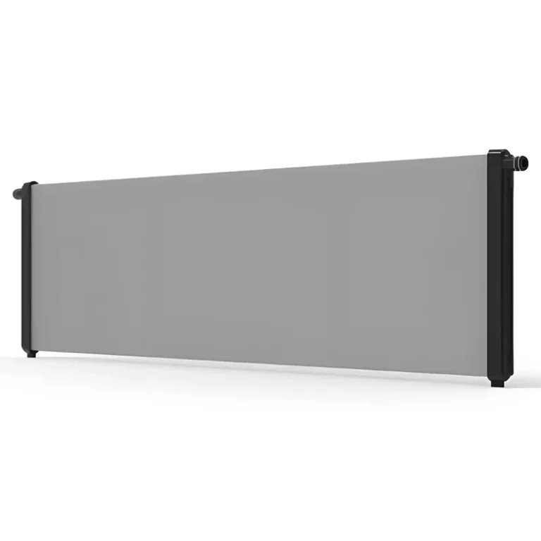
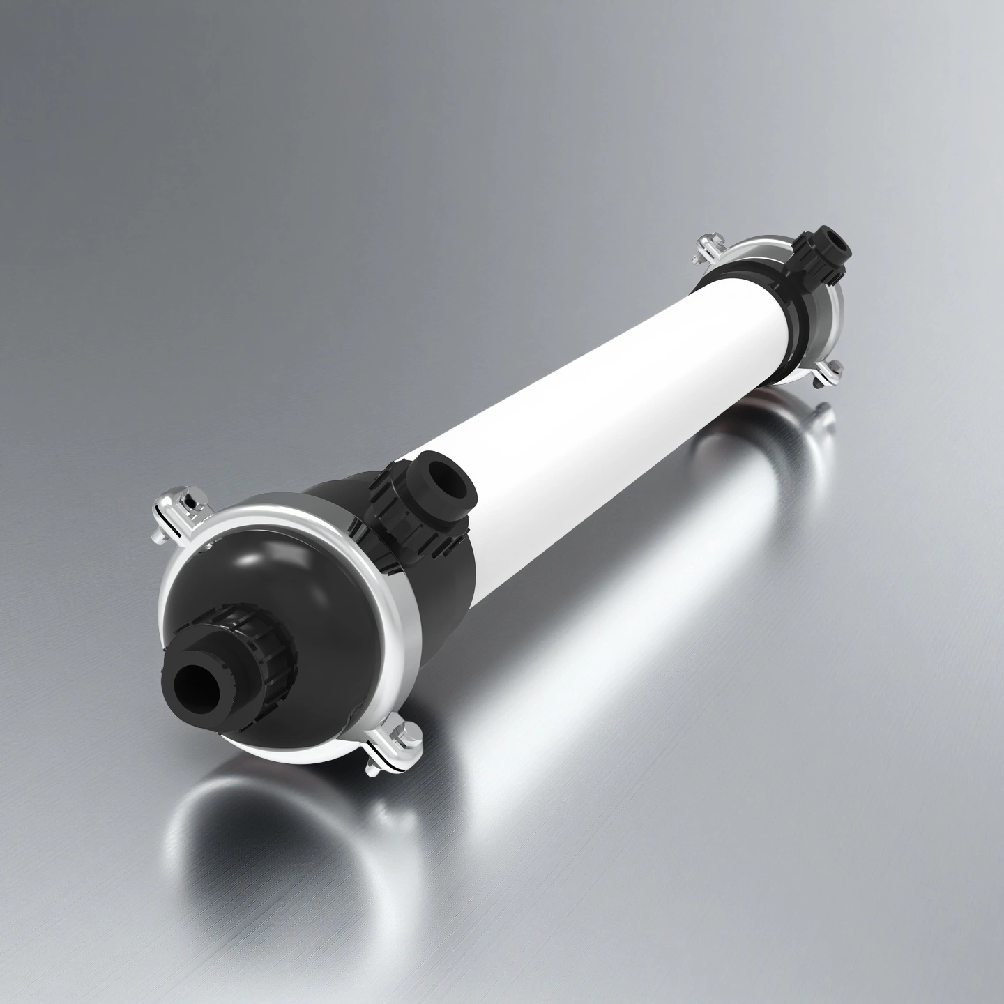
A silicon carbide ceramic column membrane module is a pressure-driven filtration component that uses a SiC ceramic membrane core to separate suspended solids, colloids, oil droplets, microorganisms and fine particles from liquid streams. Compared with polymeric membrane modules, SiC ceramic modules are selected when the feedwater contains abrasive solids, variable pH, high fouling tendency or aggressive cleaning requirements.
ADCERAX supplies column-type SiC ceramic membrane modules for water treatment systems, industrial wastewater pretreatment, RO/NF protection and process separation projects. Module configuration can be reviewed according to filtration area, pore size, housing material, flow mode, connection size and installation layout.
Advanced Material and Performance Features of Silicon Carbide Ceramic Column Membrane Module
-
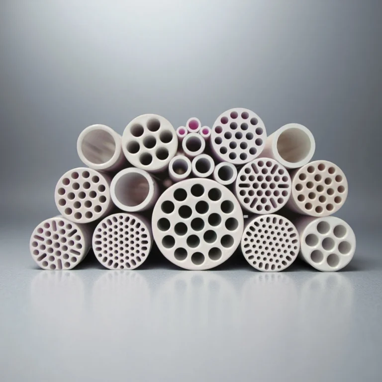
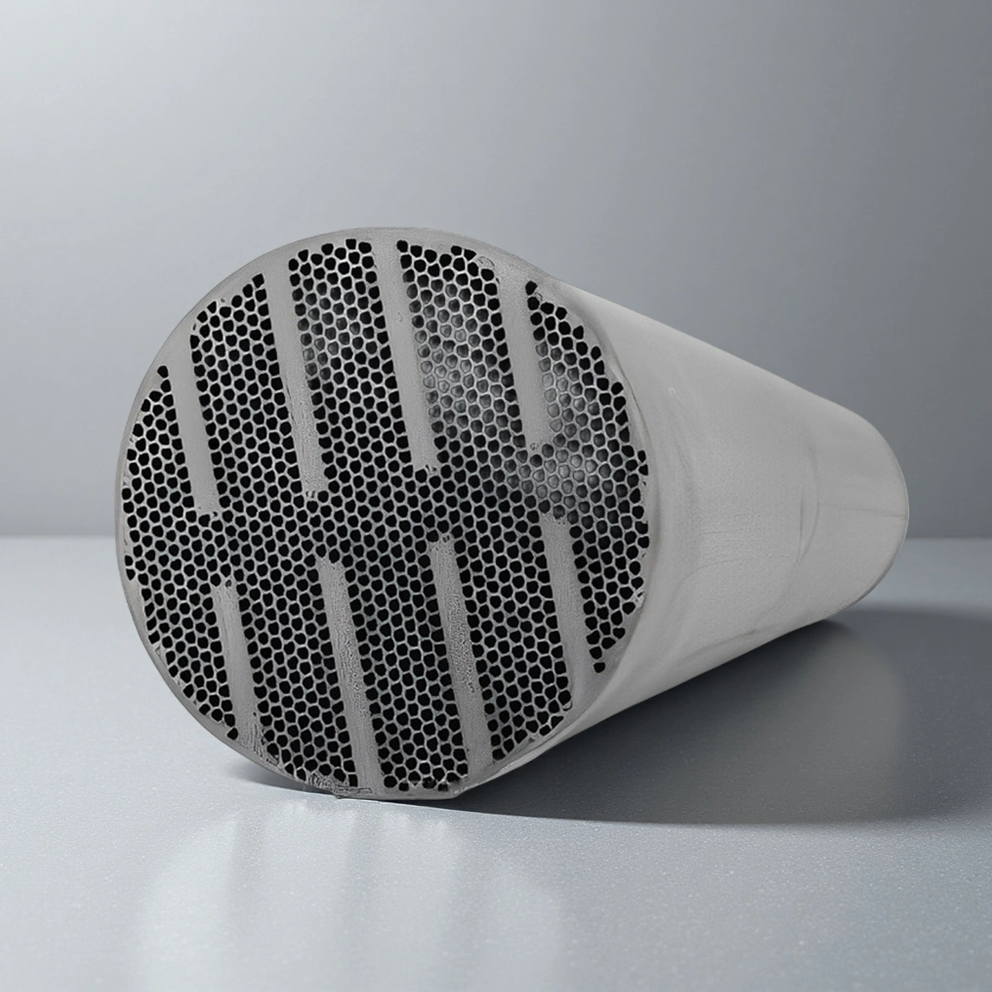
Recrystallized SiC Structure with High-Porosity Transport Pathways
-
The membrane is formed through vapor–solid–vapor sintering at 2400°C, creating continuous SiC–SiC bonding that increases mechanical rigidity and maintains structural stability under variable feed pressures. The high-temperature process prevents micro-crack formation during long filtration cycles.
-
The open-cell structure features >45% porosity, improving water transport velocity and reducing trans-membrane pressure growth over extended operation. This level of porosity supports sustained performance even in feed streams containing elevated TSS loads.
-
Channel abrasion resistance is enabled by the inherent hardness of recrystallized SiC measured at Mohs 9, preventing erosion when handling particle concentrations commonly exceeding 500 mg/L in mining and industrial wastewater.
-
-
Intrinsic Hydrophilicity and Low Contact Angle Surface Behavior
-
The SiC surface maintains a measured contact angle of 0.3°, eliminating the need for external hydrophilic coating and enabling rapid wetting at system start-up. This property reduces air-locking events and stabilizes flux during the first filtration cycles.
-
The negative surface charge, with an iso-electric point near pH 3, lowers adsorption of colloids and organics across typical operating pH ranges from 2–12, reducing irreversible fouling accumulation. These electrostatic conditions improve flux recovery following chemical cleaning.
-
Flux performance reaches up to 3200 LMH in clean-water tests, which is 2–5× higher than polymeric UF membranes operating under similar pressure conditions. This permeability advantage compensates for high-turbidity or oil-bearing feedwater fluctuations.
-
-
Chemical and Thermal Stability Across Harsh Operating Conditions
-
The membrane maintains full chemical resistance across pH 1–14, allowing the use of strong acids, alkalis, and oxidants such as ozone and hydroxyl radicals. This compatibility supports aggressive cleaning cycles required in high-COD industrial wastewater.
-
Thermal operating stability is maintained from 1–45°C, allowing the module to withstand temperature variation during shutdown and restart conditions. These thermal margins reduce stress fractures that are common in lower-density ceramic membranes.
-
The module tolerates operating pressures up to 6 bar and maximum cross-flow TMP of 3 bar, enabling reliable performance during pressure surges and seasonal hydraulic fluctuations in municipal and RO pretreatment facilities.
-
Technical Specifications of Silicon Carbide Ceramic Column Membrane Module
The Silicon Carbide Ceramic Column Membrane Module operates with stable filtration efficiency under extreme chemical, thermal, and hydraulic conditions, supported by the material properties of recrystallized SiC, high-porosity transport channels, and a multi-channel geometry engineered for consistent flow and low fouling behavior.
| Property | Specification |
| Material | Recrystallized Silicon Carbide (R-SiC) |
| Porosity Level | >45% open-cell network |
| Filtration Precision | 0.1 μm / 0.04 μm |
| Contact Angle | 0.3° intrinsic hydrophilicity |
| Pure Water Flux | Up to 3200 LMH |
| Operating pH Range | 1–14 |
| Chemical Cleaning pH Range | 1–13 |
| Oxidant Resistance | Compatible with ozone & hydroxyl radicals |
| Operating Temperature Window | 1–45°C |
| Maximum Operating Pressure | 6 bar |
| Maximum Trans-Membrane Differential | 3 bar |
| Flow Configuration | Dead-end / Cross-flow (internal pressurization) |
| Surface Charge Behavior | Negative charge above pH 3 |
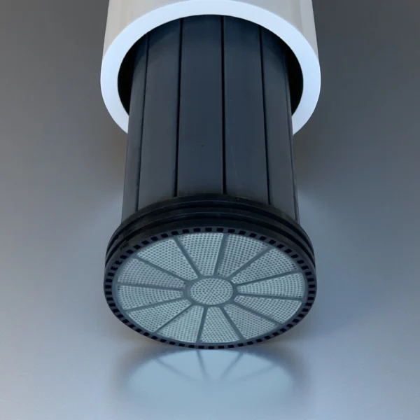
| Membrane Geometry | Multi-channel hydrodynamic structure |
| Housing Material Options | UPVC / FRP / Stainless Steel |
Available SiC Ceramic Membrane Module Models for Project Review
| Specifications Parameters | |
|---|---|
| Effective Filtration Area | 11m² |
| Total Length | 2195mm |
| Center Distance | 1613mm |
| Diameter | 200mm |
| Flow Channel Diameter | 4.5mm |
| Inlet/Concentrate Port Size | DN150 |
| Permeate Port Size | DN50 |
| Membrane Housing Material | UPVC |
| Ceramic Membrane Core Material | Silicon Carbide |
| Filtration Precision | 0.02/0.04μm |
| Installation Method | Vertical |
| Operating pH Range | 2-12 |
| Chemical Cleaning pH Range | 1-13 |
| Max Operating Pressure | 6bar |
| Max Transmembrane Pressure Difference | 3bar |
| Operating Temperature Range | 1-45℃ |
| Design Flux | 150-400 LMH |
| Filtration Method | Dead-end/Cross-flow, Inside-out Operation |
| Backwash Flux | 200-600 LMH |
| Forward Flush | 1-2 times the permeate capacity |
| Tubular Silicon Carbide Membrane | |||||||
| Model | Effective Filtration Area | Total Length | Membrane Shell Diameter | Membrane Shell Material | Ceramic Membrane Core Material | Filtration Precision | Installation Method |
| AT-SICZ-1 | 11m² | 1702mm | 250mm | UPVC | Silicon Carbide | 0.1/0.04 μm | Vertical |
| AT-SICZ-2 | 13.5m² | 1702mm | 250mm | UPVC | Silicon Carbide | 0.1/0.04 μm | Vertical |
| AT-SICZ-3 | 14.5m² | 2102mm | 250mm | UPVC | Silicon Carbide | 0.1/0.04 μm | Vertical |
| AT-SICZ-4 | 17.5m² | 2102mm | 250mm | UPVC | Silicon Carbide | 0.1/0.04 μm | Vertical |
| AT-SICZ-5 | 21.0m² | 2102mm | 250mm | UPVC/Stainless Steel/Fiberglass | Silicon Carbide | 0.1/0.04 μm | Vertical |
| AT-SICZ-6 | 25m² | 1885mm | 245mm | Fiberglass | Silicon Carbide | 0.1/0.04 μm | Vertical |
| AT-SICZ-7 | 11m² | 2195mm | 250mm | UPVC | Silicon Carbide | 0.02/0.04um | Vertical |
| AT-SICZ-8 | 11.5m² | 1960mm | 250mm | UPVC | Silicon Carbide | 0.02/0.04um | Vertical |
| AT-SICZ-9 | 25.6m² | 1885mm | 245mm | Fiberglass | Silicon Carbide | 0.02/0.04um | Vertical |
| AT-SICZ-10 | 21m² | 1885mm | 245mm | Fiberglass | Silicon Carbide | 0.02/0.04um | Vertical |
How to Select the Right SiC Ceramic Column Membrane Module?
| Selection Factor | What to Confirm Before Quotation | Engineering Impact |
|---|---|---|
| Feedwater Type | Surface water, wastewater, produced water, brine, chemical wastewater or process liquid | Different foulants require different pore size, flow mode and cleaning strategy. |
| Target Filtration Goal | TSS removal, turbidity reduction, RO pretreatment, oil-water separation or water reuse | Defines whether MF or UF precision is more suitable. |
| Solids and Fouling Load | TSS, turbidity, oil, COD, silica, biological load and scaling tendency | Helps decide cross-flow need, backwash frequency and cleaning chemistry. |
| Required Capacity | Flow rate, operating hours and module quantity | Determines filtration area and skid configuration. |
| Chemical Cleaning Plan | Acid, alkaline, oxidant or combined CIP | Ensures housing, gasket and membrane selection are compatible. |
| System Interface | Port size, flange standard, installation space and pipeline layout | Reduces integration risk during retrofit or skid assembly. |
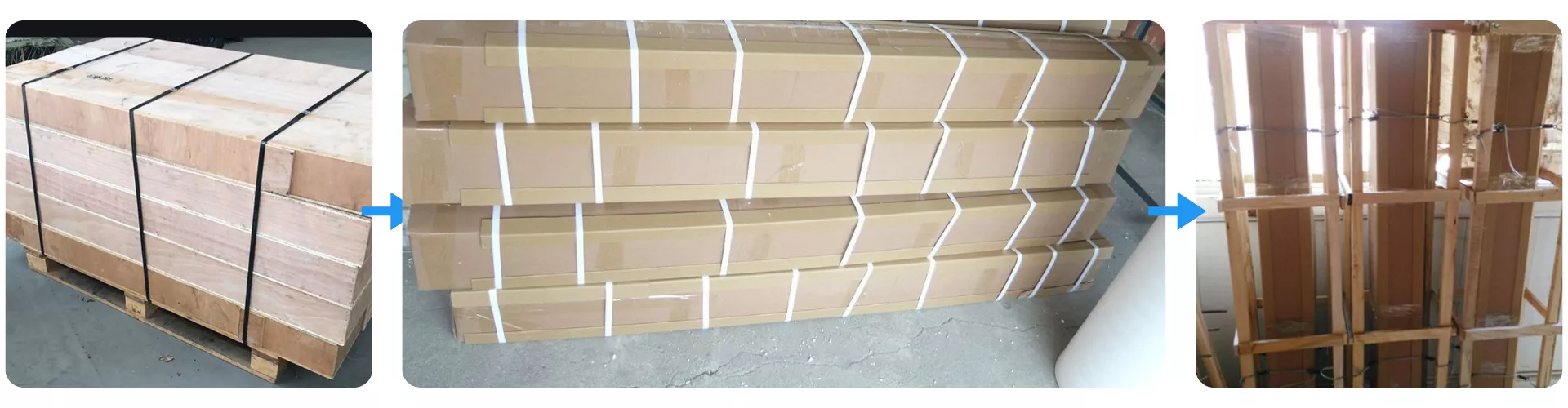
Packaging and Protection for Silicon Carbide Ceramic Column Membrane Module
Silicon Carbide Ceramic Column Membrane Module is packed in reinforced multi-layer cartons to ensure safe handling during international transport. Each unit is further secured with internal cushioning and moisture-resistant wrapping to prevent vibration and surface damage. The outer wooden frame provides added rigidity for long-distance shipping and maintains structural safety during loading, storage, and on-site delivery.