Ceramic Substrate for Electronics Power Modules & Custom Drawing Review
ADCERAX is a factory-direct supplier of ceramic substrate blanks and build-to-print parts in Al₂O₃ (alumina), AlN, Si₃N₄ and ZTA, serving ceramic PCB platforms, power electronics thermal paths, LED heat-spreader builds, and high-voltage insulation assemblies. Controlled material selection, flatness management and critical tolerance control help prevent warpage-related assembly issues, thermal bottlenecks and insulation failures.
Send a drawing with thickness, flatness, holes/vias and metallization needs — we review material route and manufacturability before quoting.
What is Ceramic Substrate?
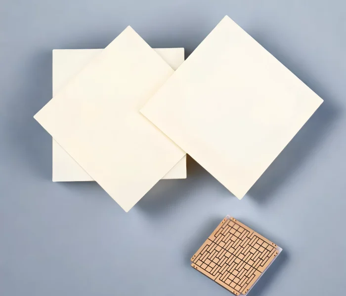
A ceramic substrate is an electrically insulating carrier made from engineering ceramics (such as Al₂O₃, AlN, or Si₃N₄) that supports circuits or devices while helping move heat away from the assembly.
Compared with standard PCB materials, it is chosen when you need better heat handling, stronger electrical isolation, and more stable dimensions under temperature change for reliable industrial electronics builds.
Choose Your Ceramic Substrate Material
The right route depends on your thermal load, voltage, mechanical stress and cost target — compare the four below. Not sure? Send your power/thermal target and we confirm the route before quoting.
| Card / Suggested Icon | Choose It When | Boundary | Tag |
|---|---|---|---|
| AlN — Aluminum Nitride 🔥 | Choose AlN when heat spreading is the main bottleneck, such as in power modules, high-power LEDs, and laser diode submounts. | AlN costs more than alumina. The suitability of DBC, AMB, or DPC metallization should be confirmed for each part. | High thermal conductivity |
| Al₂O₃ — Alumina 🛡️ | Choose alumina when you need cost-effective electrical insulation for general electronics, thick-film or thin-film circuits, and LED circuits. | Its thermal conductivity is approximately 20–35 W/m·K, which is lower than that of AlN. The required grade, such as 96% or 99.6% alumina, should be confirmed for each part. | General insulation / cost-effective |
| Si₃N₄ — Silicon Nitride ⚙️ | Choose silicon nitride when mechanical strength and thermal-cycling reliability are critical, especially for IGBT and SiC power modules. | The AMB process route and thermal-conductivity grade should be confirmed for each part. Silicon nitride is not the lowest-cost option. | High strength / thermal cycling |
| ZTA — Zirconia-Toughened Alumina 💎 | Choose ZTA when resistance to edge chipping and cracking is important under shock, vibration, or repeated handling. | Its thermal conductivity is lower than that of AlN, so it is not suitable for applications requiring the highest heat-spreading performance. | Toughness / edge durability |
- Heat spreading is the bottleneck → AlN
- General insulation, cost-balanced → Al₂O₃
- Strength & thermal cycling → Si₃N₄
- Edge-chipping / crack resistance → ZTA
Ceramic Substrates and Components
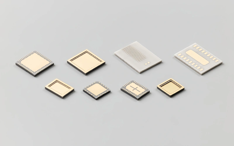
Explore ceramic substrate and related components across common material systems and build types—from Al₂O₃, AlN, Si₃N₄ and ZTA to SiC, BeO, sapphire and YSZ—with options for standard blanks or build-to-print parts.
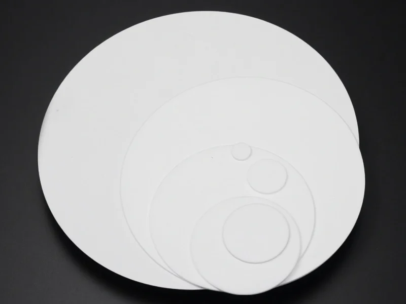
alumina ceramic substrate
Cost-balanced electrical insulation for general electronics, thick/thin-film and LED circuits — stable geometry, proven value.
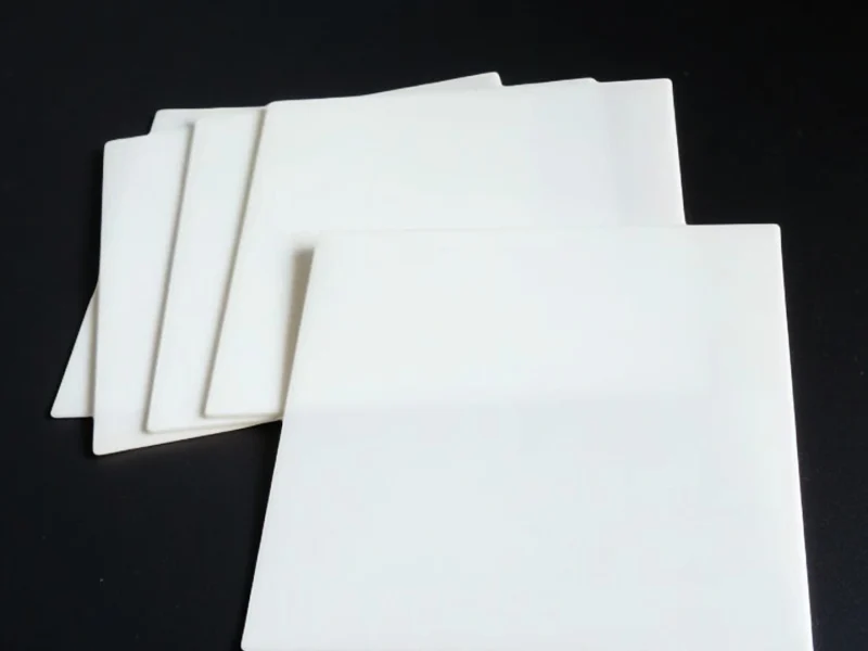
ZTA ceramic Substrates
Higher crack and edge-chip resistance for machined and handled parts — tough where plain alumina cracks.
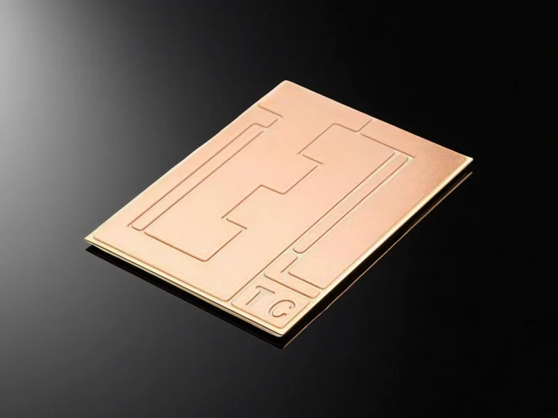
aluminum nitride substrate
High thermal conductivity with strong insulation — pulls heat from power modules, high-power LED and laser submounts.
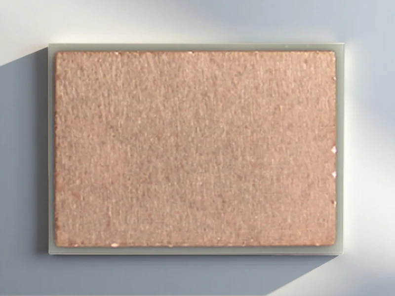
silicon nitride substrate
High mechanical strength and thermal-cycling reliability — built for stressed IGBT / SiC power modules.
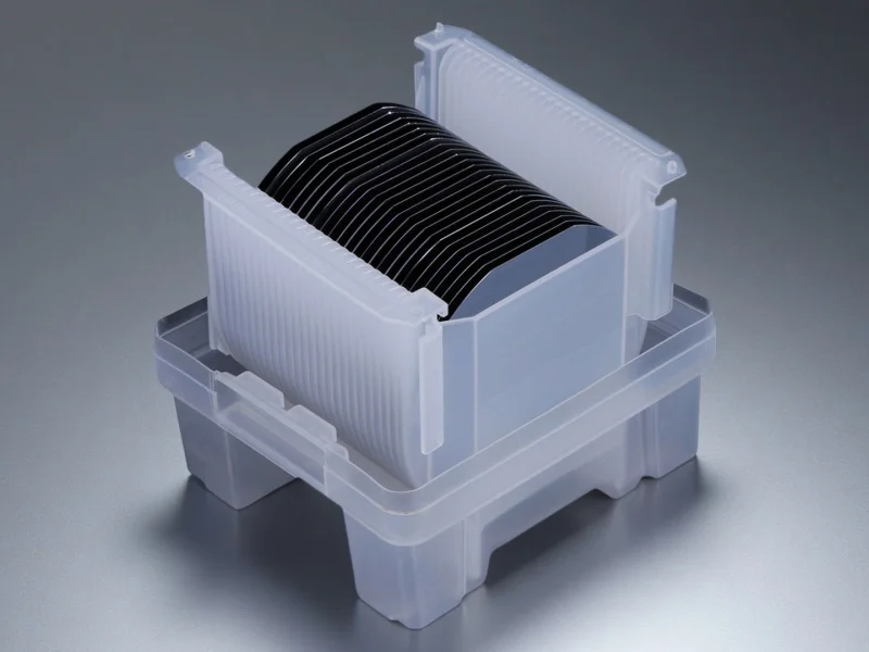
silicon carbide substrates
High stiffness, wear and chemical resistance — stable in corrosive, high-temperature electronic and thermal duty.
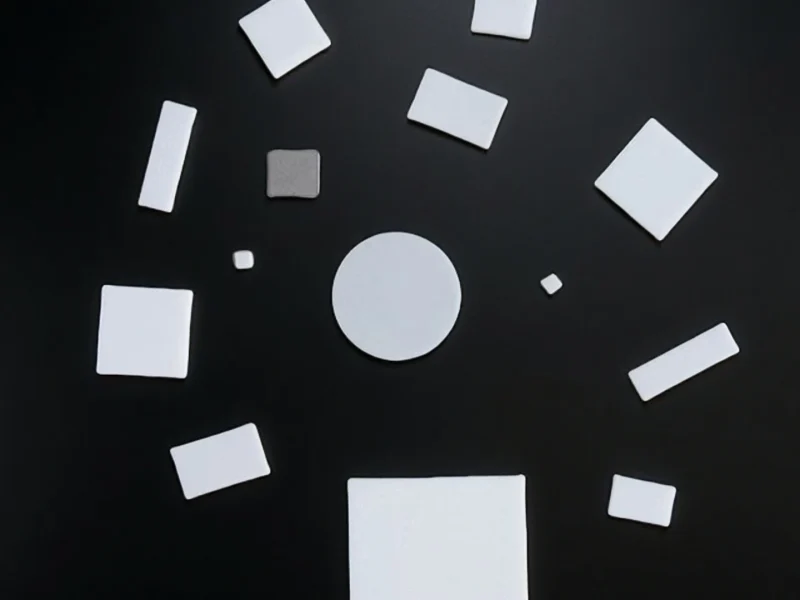
Beryllium Oxide Substrates
Very high thermal conductivity and insulation for heat-dense RF and power packages — handling/compliance confirmed per part.
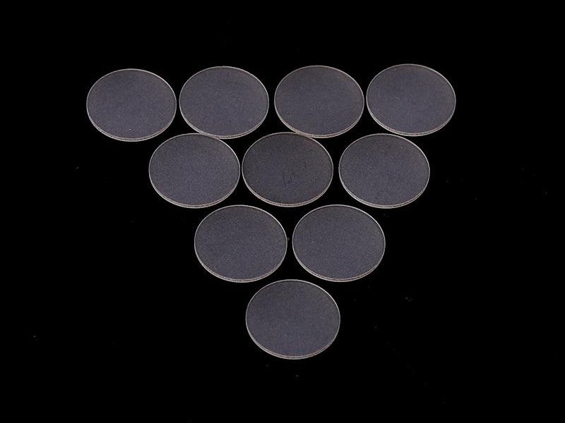
Sapphire Substrate
Optical-grade stability and dielectric strength for durable windows, sensors and RF / photonic packages.
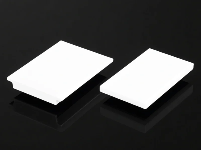
YSZ Ceramic Substrate
Tough, thermally stable insulation with strong thermal-shock resistance for fixtures in harsh thermal cycling.
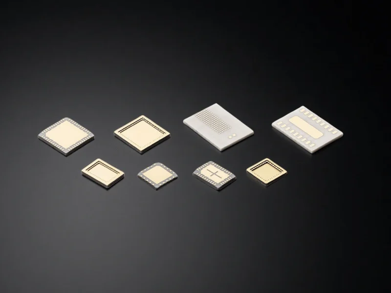
HTCC Ceramic Substrate
Strong insulation and structural stability at high temperature — for multilayer circuits and ceramic packages.
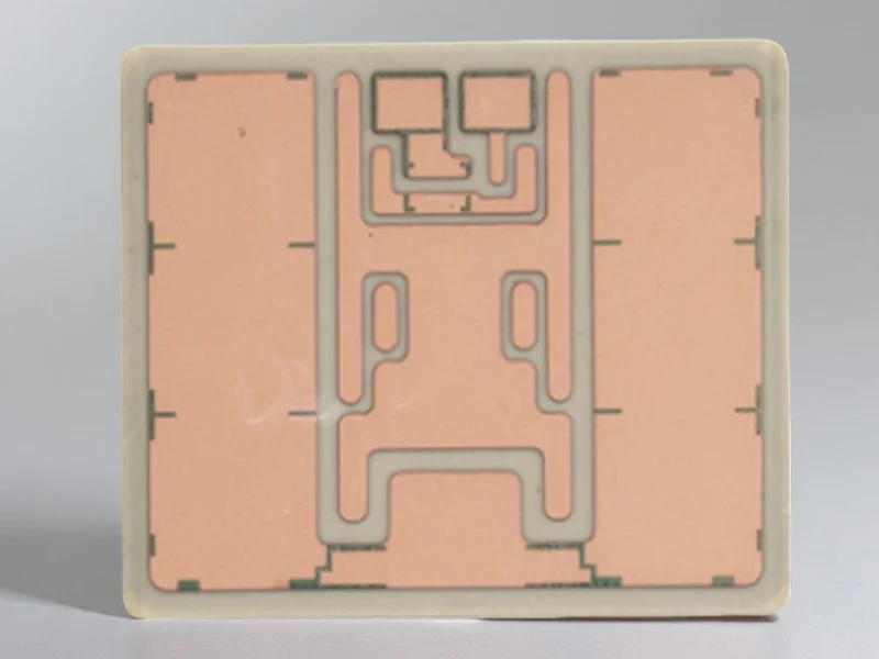
AMB Ceramic Substrate
High metal-to-ceramic bond strength — improves thermal-cycling reliability in power modules and harsh-duty assemblies.
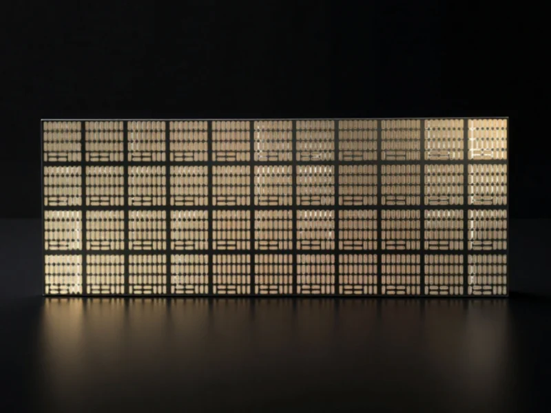
Metallized Ceramic Substrates
Solderable, bondable conductor layers on ceramics — precise interconnects, stable heat paths, consistent assembly yield.
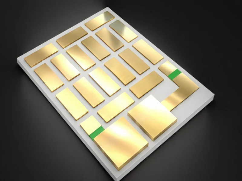
ceramic substrate circuit board
Stable insulation and heat spreading for reliable traces and consistent performance in compact power electronics.
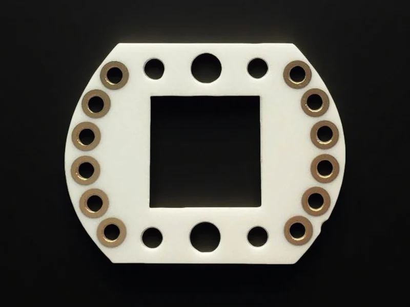
RF ceramic substrate
Controlled dielectric behavior and low loss — keeps signal integrity in microwave and high-frequency circuits.
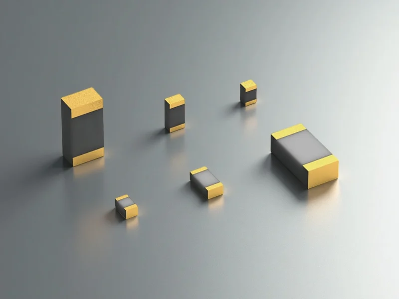
Heat Spreader Ceramic Substrate
Moves heat efficiently while staying insulating — cuts hot spots under power devices and LED modules.
Ceramic Substrate Properties
Ceramic substrates provide reliable electrical insulation, controlled flatness, and stable geometry under heat, reducing warpage-related assembly issues. They also support efficient heat spreading and consistent dielectric performance.
Alumina Ceramic Substrate
Alumina substrates (Al₂O₃) offer reliable electrical insulation, stable geometry at elevated temperatures, and cost-effective performance for ceramic PCBs, heater parts, and general electronic assemblies.
| Property | Unit | 96% Al₂O₃ | 99.6% Al₂O₃ | 99.7% Al₂O₃ | 99.99% Al₂O₃ |
|---|---|---|---|---|---|
| Alumina content | % | 96 | 99.6 | 99.7 | 99.99 |
| Density | g/cm³ | 3.60–3.75 | 3.91 | 3.92 | 3.98 |
| Flexural strength | MPa | 260 | 345 | 346 | 365 |
| Hardness (HV) | GPa | 14.5 | 23 | 24 | 30 |
| Thermal conductivity | W/m·K | 20 | 31–33 | 31–33 | 31–35 |
| CTE | ×10⁻⁶/K | 7.6 | 7.6 | 7.5 | 7.4 |
| Dielectric strength | kV/mm | 15 | 23.2 | 23.4 | 24 |
| Volume resistivity | Ω·cm | >1 × 10¹⁴ | >1 × 10¹⁴ | >1 × 10¹⁴ | >1 × 10¹⁴ |
| Maximum use temperature, no load | °C | 1450 | 1755 | 1760 | 1800 |
*Typical values for sintered alumina; certified values for a specific part are confirmed by Engineering Review.
Zirconia Toughened Alumina Ceramic Substrate
ZTA substrates combine alumina’s rigidity with zirconia toughening to improve fracture resistance, helping reduce edge chipping and cracking in fixtures and electronic assemblies under shock, vibration, or repeated handling.
| Property | Unit | Typical Range | Why Buyers Specify It |
|---|---|---|---|
| Density | g/cm³ | 4.00 – 4.30 | Indicates densification and batch consistency |
| Flexural Strength | MPa | 700 – 1,200 | Impacts handling breakage risk and safety margin |
| Fracture Toughness | MPa·√m | 6 – 10 | Key ZTA advantage for edge-chipping and crack resistance |
| Hardness (Vickers) | GPa | 14 – 17 | Affects wear/scratch resistance and machinability |
| Thermal Conductivity | W/m·K | 18 – 30 | Drives heat spreading performance (typically below AlN) |
| CTE (20–300°C) | ×10⁻⁶ /K | 8.0 – 9.5 | Influences thermal-cycling stress and material matching |
| Dielectric Strength | kV/mm | 10 – 15 | Determines insulation margin (depends on thickness/surface) |
| Volume Resistivity (25°C) | Ω·cm | 10¹² – 10¹⁴ | Indicates insulation stability and leakage risk |
- Values are typical ranges; they vary with ZrO₂ content, firing profile, and final density.
Silicon Carbide Substrate
Silicon carbide substrates deliver high stiffness and chemical resistance, maintaining stable performance in corrosive, abrasive, or high-temperature electronic and thermal-duty environments.
| Property | Unit | RBSiC / SiSiC | SSiC (Sintered) |
|---|---|---|---|
| Density | g/cm³ | 3.02–3.05 | 3.10–3.15 |
| Flexural strength | MPa | 250–300 | 380–450 |
| Elastic modulus | GPa | 330 | 410–420 |
| Thermal conductivity | W/m·K | ~45 | ~70–110 |
| CTE | ×10⁻⁶/K | 4.0–4.5 | 4.0–4.5 |
| Maximum use temperature | °C | ≤1380 | ≤1600 |
| Hardness (HV) | GPa | ~24–26 | ~25–28 |
- Please note: Values are typical ranges and may vary by grade, forming method, density and final machining requirements.
Silicon Nitride Substrate
Silicon nitride substrates combine high strength with excellent thermal-shock and thermal-cycling stability, supporting reliable builds in mechanically stressed power and industrial electronics.
| Property | Unit | Standard Si₃N₄ | High-TC / AMB Si₃N₄ |
|---|---|---|---|
| Density | g/cm³ | 3.2–3.3 | 3.2–3.3 |
| Flexural strength | MPa | 600–800 | 700–900, typically ~850 for AMB grades |
| Fracture toughness | MPa·√m | 5–7 | 5–7 |
| Thermal conductivity | W/m·K | 15–30 | 80–90 |
| CTE (20–300°C) | ×10⁻⁶/K | 3.0–3.4 | 3.0–3.4 |
| Dielectric strength | kV/mm | ≥19 | ≥19 |
| Volume resistivity (25°C) | Ω·cm | ≥10¹⁴ | ≥10¹⁴ |
| Thermal shock resistance (ΔT) | °C | 550–600 | 550–600 |
*Typical values for sintered/technical ceramics; certified values for a specific part are confirmed by Engineering Review.
One Drawing, a Cost Breakdown You Can Act On
Send your drawing or target specs. We confirm the material route and manufacturability first, then quote with standard vs enhanced QC options and practical lead-time routes to match your project stage.
Ceramic Substrate Applications
Ceramic substrate applications in industrial electronics focus on stable insulation and heat control where standard boards can drift, warp or overheat — with the right material route for each use.
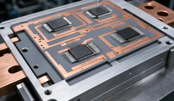
Power Electronics & Industrial Drives
Reduce hot-spot rise and insulation failure in high-power builds.
In inverters, converters, motor drives and welding/induction supplies, the substrate must spread heat and hold insulation build after build. ADCERAX recommends the right route — AlN or Si₃N₄, with DBC/AMB reviewed per RFQ — and locks critical thickness, flatness and tolerance early, so warpage, poor contact and fit-up rework drop on build-to-print parts.
- Typical Material: AlN · Si₃N₄ (AMB) · DBC
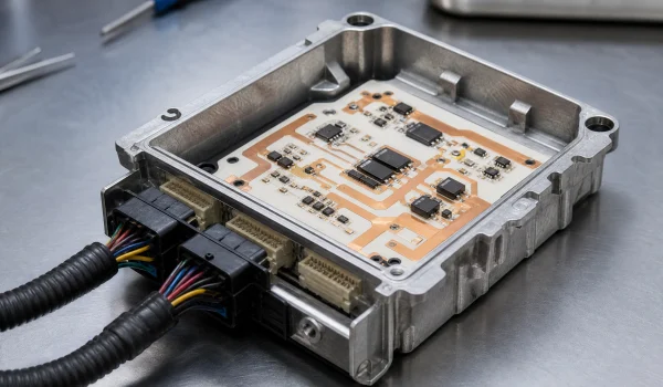
Microwave / RF Electronics
Hold signal integrity with controlled dielectric behavior and low loss.
In microwave and RF layouts, controlled dielectric behavior and stable geometry keep signal performance consistent. ADCERAX supports predictable substrate build specs and practical inspection items — dimensions, surface, flatness — to avoid lot-to-lot variation that causes tuning shifts or unexpected loss.
- Typical Material: Al₂O₃ · AlN (low-loss, geometry-stable)
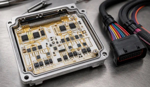
Automotive Electronics
Survive thermal cycling and vibration in electronic modules (not honeycomb catalyst).
In automotive electronic modules, ceramic substrates hold insulation and heat control under vibration and temperature cycling. ADCERAX reduces thermal-cycling and dimension-drift failures with the right material choice, consistent batch QC, and edge-spec and packaging guidance that prevents chipping.
- Typical Material: AlN · Al₂O₃ · Si₃N₄
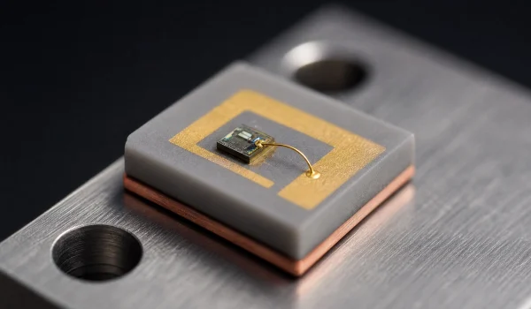
LED & Laser Submounts
Reduce the thermal bottleneck and bonding variation in light-source builds.
For LED and laser-diode submounts, a rigid, insulating base pulls heat away from the die to stabilize output and service life. ADCERAX controls flatness, surface finish and edge condition to cut voiding, uneven bonding and yield loss, and supports fast iteration from samples to batch supply.
- Typical Material: AlN · Al₂O₃ · metallized submount
Custom Ceramic Substrates — Options & Process
ADCERAX is a ceramic substrate manufacturer focused on custom ceramic substrates made to your drawing or sample. We offer custom sizes and thickness, tight tolerances, controlled flatness/warpage, holes/slots/profiling, edge chamfers, and QC checkpoints, with low-MOQ prototyping and repeatable supply.
Customization Options
Custom L×W, thickness, controlled flatness/warpage, and defined hole/slot positional tolerance.
Provide higher - level dimensional accuracy and concentricity control than the standard.
Flanges, steps, threads, drilling holes, grooves, etc.
Adjust the material according to the application requirements.
Polish and grind the surface to achieve a specific surface roughness.
Customization Process
Send us your drawing, CAD file, or physical sample with material grade, dimensions, tolerances, and quantity. Our engineers will evaluate the design and provide a detailed quotation with lead time and pricing.
Once the quote is approved, we proceed with sample prototyping (1–50 pcs) if needed, for testing and validation.
After sample approval or direct confirmation, we begin batch manufacturing using CNC machining, sintering, and polishing. All parts undergo dimensional checks, material purity testing, and surface finish inspection.
Finished products are securely packed and shipped via DHL/FedEx/UPS or your preferred method. We support global delivery with full documentation.
ADCERAX: A Trusted Ceramic Substrate Manufacturer
ADCERAX is a specialized ceramic substrate manufacturer, supplying standard blanks and build-to-print substrates with controlled material quality, flatness, and tight dimensional consistency. Our engineering support, sampling service, and export experience simplify global sourcing and reduce project risk.
Direct-from-manufacturer supply with strict quality control from raw material to delivery — engineering-grade value, not a price war.
We check material route, flatness, holes/vias and metallization before quoting — a straight, honest answer.
Small batch orders to large-scale production with complex geometries and tight tolerances
24-hour response and 24-hour dispatch for standard items, 3-7 weeks for custom orders.
Ceramic Substrate Manufacturing Process
Our ceramic substrate manufacturing is designed to control the three things buyers care about most—material consistency, flatness/warpage, and dimensional repeatability from sample to batch supply.

Step 1 — Material Selection & Batch Control
We confirm your thermal load, voltage, and RF frequency (if needed), then select Al₂O₃, AlN, Si₃N₄, ZTA, or SiC. Powder batching is controlled for stable density and properties across lots.
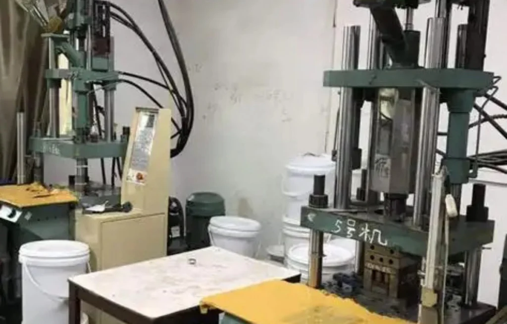
Step 2 — Forming & Green Machining
Substrates are formed into plates/blanks, then green machining is used where applicable to create near-net shapes. This step reduces machining cost and helps maintain geometry consistency for build-to-print parts.
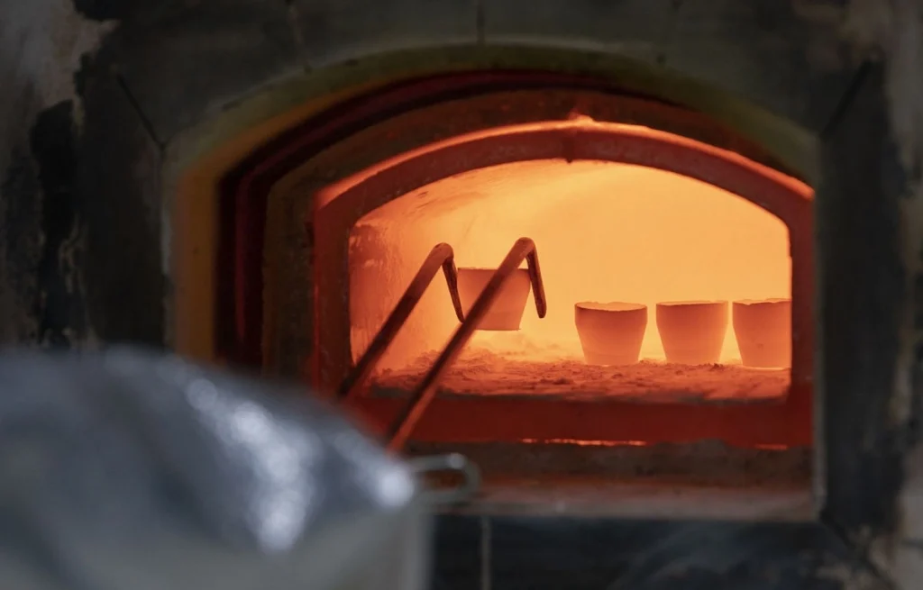
Step 3 — Sintering (Firing) for Density and Stability
The firing cycle is tuned for the selected material to reach target density and mechanical stability. Controlled sintering is a key driver of flatness stability and long-term reliability in service.
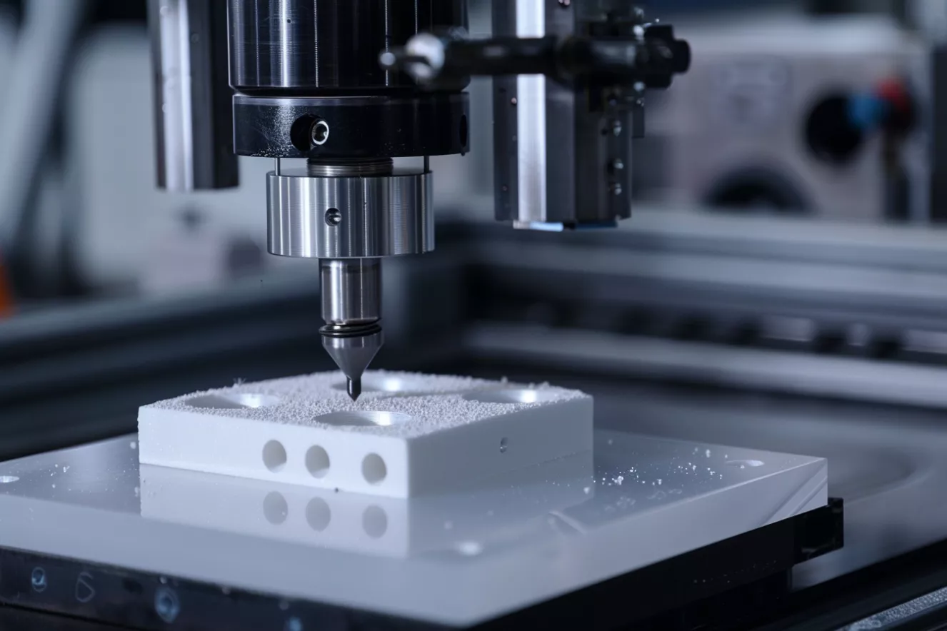
Step 4 — Precision Machining (to Print)
CNC grinding and finishing bring the substrate to final size, thickness tolerance, and edge condition. Common features include holes, slots, profiles, and chamfers, with attention to chipping control.
Step 5 — Surface Finish & Flatness Control
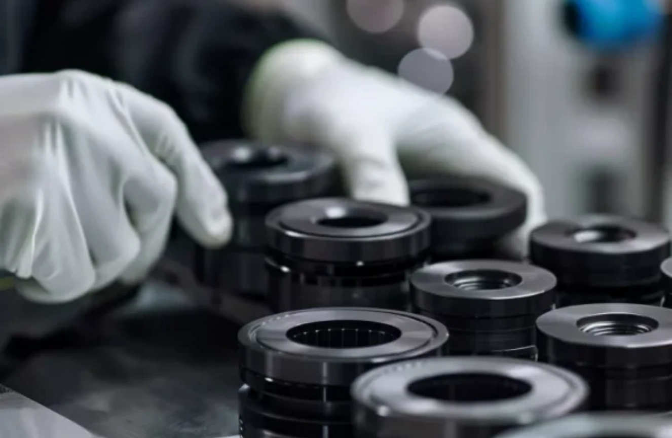
Surface condition and flatness are managed to match the assembly method (bonding, soldering, brazing, clamping). This step is where many yield issues are prevented, especially for tight-contact thermal interfaces.
Step 6 — Metallization / Coating (Optional)
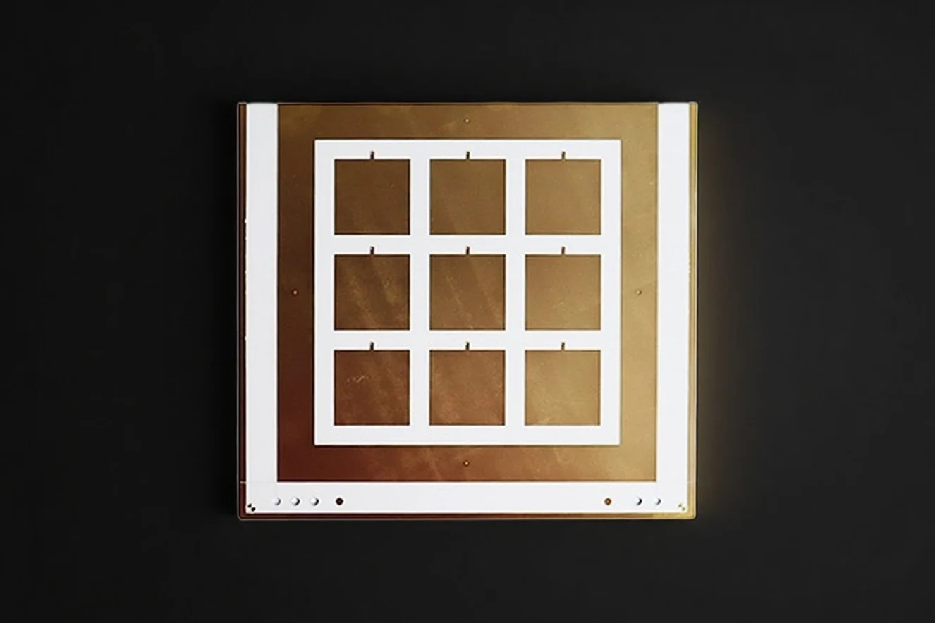
For conductive or solderable areas, we review thick-film, thin-film, DBC, AMB and DPC case by case. Copper thickness, line/space and multilayer co-firing need engineering review — no default full-line promise.
Ceramic Substrates Cutting
Ceramic substrates cutting is used to achieve clean outlines, tight dimensions, and repeatable features on Al₂O₃, AlN, Si₃N₄, ZTA, and SiC substrates—while minimizing chipping and scrap.
📌 Laser Cutting
Fast for profiles and complex shapes; ideal for prototypes and small-to-mid batches.
Choose it when you need finished outlines, complex profiles or full through-cuts in one step, for prototypes and small-to-mid batches with clean edges.
📌 Laser Scribing
Controlled scoring for panel separation; helps improve throughput and consistency.
Choose it when you need to score panel arrays now and snap them apart after processing — high throughput with low edge-chipping on thin substrates.
📌Laser Drilling
Micro-holes and dense patterns when mechanical drilling risks chipping or tool wear.
Choose it when you need micro-holes, dense via patterns, or tight pitch features where mechanical drilling may crack edges or wear tools fast.
📌Laser Profiling
Contoured outlines, windows, and internal cutouts with stable repeatability.
Choose it when you need tight-tolerance contours and internal windows on thicker or harder ceramics, where repeatable geometry matters most.
FAQs About Ceramic Substrate
No. Ceramic substrates are electrically insulating dielectric structural materials, not semiconductors. Their main role is to support circuits or devices, provide electrical isolation, and help manage heat and dimensional stability in an assembly.
Ceramic substrates are used when FR4 cannot meet the thermal, electrical or dimensional stability requirements of the design. Compared with FR4, ceramic substrates can provide higher thermal conductivity, better high-temperature stability, lower CTE mismatch with semiconductor devices, stronger electrical insulation and better mechanical stability. They are commonly reviewed for power electronics, RF circuits, LED modules and harsh-environment assemblies.
Yes. ADCERAX reviews custom ceramic substrates by drawing, material, dimensions, thickness, tolerance, surface finish, holes, slots, scoring, edge design and metallization requirements. Please send your application, quantity and working conditions so our engineering team can confirm the suitable material route and manufacturability before quotation.
We review metallization case by case, including thick-film, thin-film, DBC, AMB and DPC routes. The right option depends on circuit complexity, current, voltage, frequency, copper thickness and line/space requirements. Final metallization feasibility is confirmed by engineering review, and we do not promise every metallization route by default.
Selecting the right ceramic substrate depends on the main performance bottleneck. Use AlN when heat spreading is critical, Al₂O₃ when cost-balanced insulation is the priority, Si₃N₄ when thermal cycling and mechanical stress are key risks, and ZTA when edge chipping or crack resistance matters.
Electrical requirements, operating temperature, CTE matching, flatness, tolerance and assembly process should also be reviewed before the material is confirmed.
Ceramic substrates can be compatible with soldering, die attach, wire bonding and encapsulation when the material, surface finish and metallization stack are properly specified. Compatibility depends on the selected metallization route, conductor layer, plating, bonding method and assembly temperature profile, so these details should be confirmed during drawing review.
Ceramic substrates are used for pressure sensors because they provide a stable, electrically insulating and chemically resistant platform. This helps the sensing element maintain accuracy and reliability under pressure, temperature change, moisture or corrosive working conditions.
Cost can often be reduced by simplifying geometry, relaxing non-critical tolerances, defining flatness only on functional zones, using standard thicknesses or blank sizes where possible, and selecting the material based on the real bottleneck: thermal, mechanical or electrical. Cost usually increases when tight tolerances, complex features and strict inspection requirements are applied to every surface or every piece.
Choose the material based on the dominant design risk. Al₂O₃ is a cost-balanced baseline for insulation and general electronics. AlN is selected when heat spreading is the bottleneck. Si₃N₄ is suitable when thermal cycling and mechanical stress drive failure risk. ZTA is preferred when edge chipping or crack resistance matters. SiC can be reviewed for harsh chemical or high-temperature duty where stiffness, wear resistance and chemical resistance are important.
Use alumina (Al₂O₃) when you need cost-balanced electrical insulation for general electronics, thick-film circuits or thin-film circuits.
Use aluminum nitride (AlN) when heat spreading is the main bottleneck, such as in power modules, high-power LED modules or laser submounts.
Final selection should be confirmed by thermal load, voltage, geometry and cost target.
Please provide the material route, length, width, thickness, flatness or warpage requirement, surface finish, holes, vias, slots, edges, metallization details, copper thickness, line/space, application or device type, quantity and project stage. If you have a drawing, old-part photos or failed sample information, we can review manufacturability and typical lead time more accurately.
Choose a ceramic substrate when the design needs high electrical insulation, stronger heat spreading, matched CTE and stable flatness under thermal cycling, especially when FR4 or metal-core PCB becomes the performance bottleneck. For mainstream boards with moderate thermal and voltage requirements, organic PCBs may still be the more cost-effective option.
Ceramic Substrate RFQ Checklist
Include these items with your drawing so engineering review is fast and the quotation is accurate:
- Material route — Al₂O₃ / AlN / Si₃N₄ / ZTA / LTCC–HTCC
- Length × width × thickness
- Flatness / warpage target and surface condition (as-fired, or lapped/polished)
- Holes, vias, slots and edge features
- Metallization or plating — copper thickness, layers, pattern (if required)
- Line/space and pattern drawing (for patterned parts)
- Voltage, thermal or CTE targets
- Application device — power module, LED/laser submount, sensor, package
- Quantity and stage — prototype / small batch / repeat production
Common industry thickness formats include 0.25, 0.38, 0.50, 0.635 and 1.0 mm; final dimensions and tolerances are confirmed per drawing during engineering review.
Metallization routes (thick film, thin film, DPC, DBC, AMB) are reviewed case-by-case against your drawing — we confirm the supported route before quotation.
*Our team will answer your inquiries within 24 hours.
*Your information will be kept strictly confidential.
info@adcerax.com
Tel:+86-0731-84428843
WhatsApp:+86 19311583352
Within 24 hours